
Related Manuals for Aruba Networks Aruba 52


Summary of Contents for Aruba Networks Aruba 52
-
Page 1: Wireless Access Point
7/29/03 FINAL DRAFT—CONFIDENTIAL Aruba 52 Wireless Access Point Installation Guide 180 Great Oaks Blvd. Ste B San Jose, California 95119 Net www.arubanetworks.com 408.227.4500 Fax 408.227.4550... - Page 2 Originated in the USA. Trademarks Aruba 52, Aruba 5000, and AirOS are trademarks of Aruba Wireless Networks in the United States and certain other countries. The K & Lock design is a registered trademark of the Kensington Technology Group in the United States and certain other countries.
- Page 3 Department of Communications. Cet appareil numérique respecte les limites de bruits radioélectriques applicables aux appareils numériques de Classe B prescrites dans la norme sur le matériel brouilleur: “Appareils Numériques,” NMB-003 édictée par le ministère des Communications. Aruba 52 Installation Guide...
- Page 4 7/29/03 FINAL DRAFT—CONFIDENTIAL Aruba 52 Part 0500007B Installation Guide August 2003...
-
Page 5: Table Of Contents
Direct Terminal Connection ....Configure the Aruba 52 .... - Page 6 ..... SPOE Adapter Product Specifications ..Appendix B Aruba 52 Part 0500007B Installation Guide August 2003...
-
Page 7: Preface
The following items are part of the complete documentation for the Aruba system: Aruba 5000 Installation Guide (Part No. 0500001A, June 2003) Aruba AirOS v1.1 User’s Guide (Part No. 0500002B, August 2003) Aruba 52 Installation Guide (Part No. 0500007B, August 2003) Preface... -
Page 8: Text Conventions
{ Item A | Item B } In the command examples, items within curled braces and separated by a vertical bar represent the available choices. Enter only one choice. Do not type the braces or bars. viii Aruba 52 Part 0500007B Installation Guide August 2003... -
Page 9: Contacting Aruba Wireless Networks
7/29/03 FINAL DRAFT—CONFIDENTIAL Contacting Aruba Wireless Networks Web Site Main Site http://www.arubanetworks.com Support http://www.arubanetworks.com/support E-mail Sales sales@arubanetworks.com Support support@arubanetworks.com Telephone Numbers Main 408-227-4500 408-227-4550 Sales 408-754-1201 Support 408-754-1200 Preface... - Page 10 7/29/03 FINAL DRAFT—CONFIDENTIAL Aruba 52 Part 0500007B Installation Guide August 2003...
-
Page 11: Chapter 1 Introduction
7/29/03 FINAL DRAFT—CONFIDENTIAL HAPTER Introduction The Aruba 52 is part of a comprehensive wireless network solution. The device works in con- junction with the Aruba 5000 WLAN Switch and can act as a wireless access point or air mon- itor. -
Page 12: Ethernet Compatibility
The Aruba 52 supports POE only when the FE port is connected to an IEEE 802.3af compli- ant device (such as the Aruba 5000 WS-5032 Line Card). -
Page 13: Physical Description
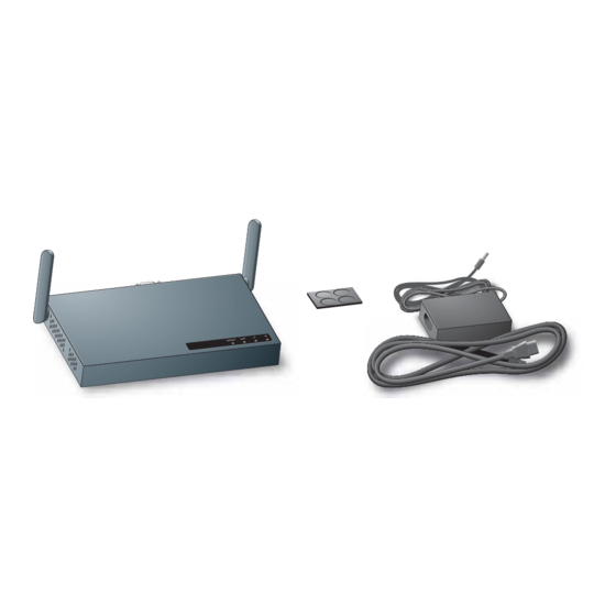
One Aruba 52 Wireless Access Point Non-slip rubber foot-pads One AC power adapter (3.3 VDC, 4 A) and power cord Assorted documentation The following optional items can also be ordered for the Aruba 52: 1-2 Optional Items IGURE Mounting kit: cradle and screws Serial &... -
Page 14: Top Panel
7/29/03 FINAL DRAFT—CONFIDENTIAL Top Panel READY .B/.G 1-3 Aruba 52 Top Panel IGURE Dual, omnidirectional Antennas for Wireless Communications (on sides) The antennas swivel and should be oriented vertically (straight up and down) away from the chassis for best performance. - Page 15 7/29/03 FINAL DRAFT—CONFIDENTIAL Indicator LEDs During operation, the Aruba 52 LEDs provide the following information: 1-1 Aruba 52 LEDs ABLE State Description Ready The device is off or initializing. Green The device has passed self-test and is operating. Flashing The device is running a self-test or loading new software. If the...
-
Page 16: Rear Panel
This slot is compatible with a Kensington MicroSaver Security Cable (not included) which can be used to prevent the unauthorized removal of the Aruba 52 from its installed location. To secure the Aruba 52, wrap a security cable around an immovable object, insert the cable’s lock into the Kensington Security Slot, and turn the key. -
Page 17: Chapter 2 Setup & Installation
One of the following power sources for the access point or air monitor: An AC power outlet rated at 100~240 V, 50~60 Hz. Power Over Ethernet (POE) capability on the device to which the Aruba 52 is con- nected (see “Power Over Ethernet”... -
Page 18: Select A Network Topology
7/29/03 FINAL DRAFT—CONFIDENTIAL Select a Network Topology The Aruba 52 can be installed in your network using the following topologies: Direct SPOE Installation Serial, Power Aruba 5000 Management & Ethernet w/SPOE Workstation Aruba 50 Data Network Mgmt. Network POE Installation... - Page 19 Serial console connectivity through the FE cable Extra console maintenance options during normal operation POE connection through the LAN In this topology, the Aruba 52 is connected to the LAN through a hub or switch that is POE compatible (see “Power Over Ethernet”...
-
Page 20: Perform Initial Setup
Connect the adapter’s 9-pin serial connector to the Console port on the back of the Aruba 52. Connect the adapter’s male RJ-45 plug to the FE port on the back of the Aruba 52. Connect the Aruba 52 to the Aruba WLAN Switch. - Page 21 [9600|19200|38400|57600|115200] connect <slot/port> exit (no args) soe> Connect to the Aruba WLAN Switch port to which the Aruba 52 is physically attached: connect <slot number>/<port number> soe> where slot number is the physical slot of the line card in the WLAN switch, and port number is the physical port.
- Page 22 7/29/03 FINAL DRAFT—CONFIDENTIAL From the Aruba 52 console, access the boot prompt. Depending on the Aruba 52 status, you will see one of the following on your terminal: Autoboot countdown—The countdown prompt allows you to interrupt the normal star- tup process and access the boot prompt where initial configuration is performed.
-
Page 23: Direct Terminal Connection
(2002) Article 300.22(C), POE must be used instead of a power outlet. If local regulations and practices permit, connect the included AC power adapter cable to the DC power socket on the rear panel of the Aruba 52 and plug it into an appropriate power outlet. - Page 24 9600 None None Connect the terminal directly to the Aruba 52. Use a standard serial cable to connect the Aruba 52 console port to a serial port on your termi- nal (see Appendix A for port specification). Establish console communication.
-
Page 25: Configure The Aruba 52
7/29/03 FINAL DRAFT—CONFIDENTIAL Configure the Aruba 52 From the boot prompt, set the intended location for the Aruba 52: apboot> setenv location <building number>.<floor number>.<device number> If you performed the recommended site survey using the Aruba WLAN Switch’s built-in planning tools, the location data for all access points and air monitors can be found on the tool’s deployment screen (see the Aruba AirOS Software Guide). - Page 26 —The software image and the configuration file are usually stored on the same server. If you are not using DNS, you must manually configure the Aruba 52 with the IP address of the master Aruba WLAN Switch: apboot> setenv serverip <switch IP address>...
- Page 27 Specify an IP address, if necessary. If using DHCP, the Aruba 52 will obtain its IP address automatically and this step can be skipped. Otherwise, the AP must be manually configured with a static IP address using the fol- lowing commands: apboot>...
-
Page 28: Mount The Aruba 52
7/29/03 FINAL DRAFT—CONFIDENTIAL Mount the Aruba 52 When initial setup is complete, mount the Aruba 52 in its intended service location. Select a location as close as possible to the center of the intended coverage area. If necessary, use the Aruba WLAN Switch’s built-in site survey software to determine the optimum loca- tions for your access points and air monitors (see your Aruba AirOS Software Guide). -
Page 29: Free-Standing Placement
For more secure installation, use the optional mounting kit. Using the Built-In Mounting Slots The keyhole-shaped slots on the bottom of the Aruba 52 can be used to attach the device to a wall or shelf. —Do not use the mounting slots to hang the Aruba 52 from the ceiling AUTION or in any place where it could fall on people or equipment. - Page 30 IGURE Secure the Aruba 52, if desired. To prevent the unauthorized removal of the Aruba 52 from its installed location, use a Kens- ington MicroSaver Security Cable (not included). Wrap the security cable around an immov- able object, insert the cable’s lock into the Kensington Security Slot on the back of the Aruba 52, and turn the key.
-
Page 31: Using The Optional Mounting Kit
7/29/03 FINAL DRAFT—CONFIDENTIAL Using the Optional Mounting Kit Use the optional mounting kit to attach the Aruba 52 to a wall, shelf, or ceiling. —Do not attach the rubber foot-pads to the Aruba 52 when using the mounting kit. Wall, Shelf, or Solid Ceiling Mount Attach the mounting cradle to the mounting surface. - Page 32 Secure the Aruba 52, if desired. To prevent the unauthorized removal of the Aruba 52 from its installed location, use a Kens- ington MicroSaver Security Cable (not included). Wrap the security cable around an immov- able object, insert the cable’s lock into the Kensington Security Slot on the back of the...
- Page 33 The T-rail clips twist onto the rails used with standard suspended-ceiling systems. Place the T-rail clips approximately 15 cm (6 inches) apart at the location where the Aruba 52 will be installed. Use the mounting cradle to gauge the appropriate distance between the clips.
- Page 34 Connect the adapter’s 9-pin serial connector to the Console port on the back of the Aruba 52. Connect the adapter’s male RJ-45 plug to the FE port on the back of the Aruba 52. Connect the Aruba 52 to the Aruba WLAN Switch.
-
Page 35: Connect Required Cables
CMP. Install cables in accordance with all applicable local regulations and practices. For port and cable details, see Appendix Connect the other end of the FE cable to the FE port on the back of the Aruba 52. Setup & Installation Chapter 2... -
Page 36: Lan Or Poe Connection
(2002) Article 300.22(C), POE must be used instead of a power outlet. If local regulations and practices permit, connect the included AC power adapter cable to the DC power socket on the rear panel of the Aruba 52 and plug it into an appropriate power outlet. - Page 37 7/29/03 FINAL DRAFT—CONFIDENTIAL Setup & Installation Chapter 2...
- Page 38 7/29/03 FINAL DRAFT—CONFIDENTIAL Aruba 52 Part 0500007B Installation Guide August 2003...
-
Page 39: Appendix A Port Specifications
7/29/03 FINAL DRAFT—CONFIDENTIAL 7/29/03 FINAL DRAFT—CONFIDENTIAL PPENDIX Port Specifications Console Port The console port is located on the back of the Aruba 52 and has a DB-9 female connector. Port pin-outs are shown in Figure A-1: Aruba 52 DB-9 Female... -
Page 40: Fe Port
7/29/03 FINAL DRAFT—CONFIDENTIAL FE Port The 10/100 Mbps Ethernet (FE) port is located on the back of the Aruba 52 and has an RJ-45 female connector. Port pin-outs are shown in Figure A-2: Aruba 50 RJ-45 Female 10/100 Mbps Ethernet... -
Page 41: Spoe Adapter
The maximum length for FE cables is 100 meters (325 feet). The Aruba 52 and SPOE adapter are plenum rated. When is installed in an air-handling space, as described in NEC (2002) Article 300.22(C), the connecting FE cable should be suit- able under NEC Article 800.50 and marked accordingly for use in plenums and air-handling... - Page 42 7/29/03 FINAL DRAFT—CONFIDENTIAL Aruba 52 Part 0500007B Installation Guide August 2003...
-
Page 43: Appendix B Product Specifications
7/29/03 FINAL DRAFT—CONFIDENTIAL PPENDIX Product Specifications The following specifications apply to the Aruba 52 Wireless Access Point (model WAP-50). Physical B-1 Physical Specifications ABLE Item Measurement Size 20.5 x 13.6 x 4 cm (8.07 x 5.35 x 1.58 in) Weight 280 gram (9.9 oz.) - Page 44 3.3 VDC, 3 A (AC adapter), or 48 VDC, 150 mA (POE) LED Indicators Ready (Power), LAN (Ethernet Link/Activity), .A and .B/.G (Access Point/Air Monitor Mode) Standards IEEE 802.3 10Base-T, IEEE 802.3u 100Base-TX, IEEE 802.11a/b/g, IEEE 802.3af Aruba 52 Part 0500007B Installation Guide August 2003...
- Page 45 7/29/03 FINAL DRAFT—CONFIDENTIAL Certifications B-4 Certifications ABLE Item Measurement Electromagnetic FCC Part 15 Class B, FCC Part 15 Class C 15.207/15.247, Compatibility FCC Part 15 Class E 15.407 ICES-003, RSS 210 (CAN) IEC 61000-4-2/3/4/6/11 EN 55022, EN55024 (89/336/EEC), ETS 300 328 (89/336/EEC), ETS 301 489 (89/336/EEC), ETS 301 893 AS/NZS 3548, RFS 29 (NZ)
- Page 46 7/29/03 FINAL DRAFT—CONFIDENTIAL Aruba 52 Part 0500007B Installation Guide August 2003...
Need help?
Do you have a question about the Aruba 52 and is the answer not in the manual?
Questions and answers