Aruba Networks AP-103 - Wireless Access Point Installation Manual
- Installation manual (2 pages) ,
- Installation manual (2 pages)
Advertisement
- 1 Introduction
- 2 Package Contents
- 3 AP-103 Hardware Overview
- 4 Before You Begin
- 5 Verifying Pre-Installation Connectivity
- 6 Identifying Specific Installation Locations
- 7 Installing the AP
- 8 Verifying Post-Installation Connectivity
- 9 Configuring the AP-103
- 10 Product Specifications
- 11 Contacting Aruba Networks
- 12 Documents / Resources
Introduction
The Aruba AP-103 wireless access point supports the IEEE 802.11n standard for high-performance WLAN. This access point uses MIMO (Multiple-in, Multipleout) technology and other high-throughput mode techniques to deliver highperformance, 802.11n 2.4GHz or 5 GHz functionality while simultaneously supporting existing 802.11a/b/g wireless services. The AP-103 access point works only in conjunction with an Aruba Controller.
The Aruba AP-103 access point provides the following capabilities:
- Wireless transceiver
- Protocol-independent networking functionality
- IEEE 802.11a/b/g/n operation as a wireless access point
- IEEE 802.11a/b/g/n operation as a wireless air monitor
- Compatibility with IEEE 802.3af PoE
- Central management configuration and upgrades through a controller
 The AP-103 requires ArubaOS 6.4.1.0 or later.
Package Contents
- AP-103 access point
- 9/16" and 15/16" Ceiling Rail Adapters
- Installation guide (this document)
 Inform your supplier if there are any incorrect, missing, or damaged parts. If possible, retain the carton, including the original packing materials. Use these materials to repack and return the unit to the supplier if needed.
AP-103 Hardware Overview
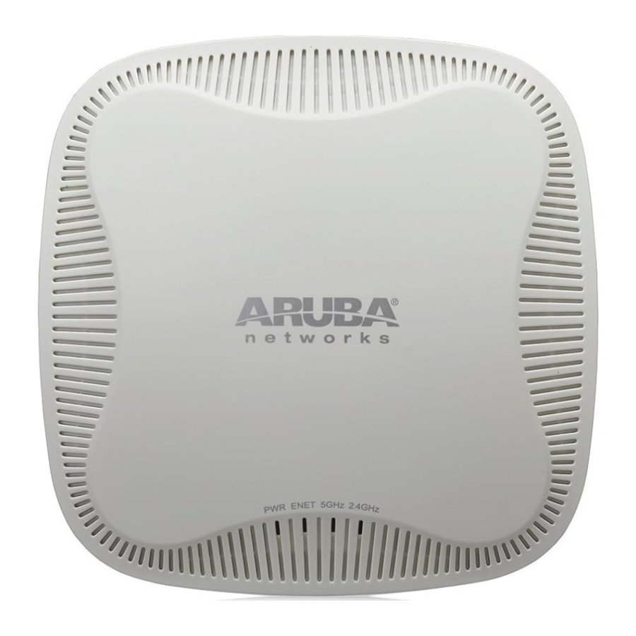
LEDs
The AP-103 is equipped with four LEDs that indicate the status of the various components of the AP.
- PWR: Indicates whether or not the AP-103 is powered-on
- ENET: Indicates the status of the AP-103' Ethernet port
- 5 GHz: Indicates the status of the 802.11a/n radio
- 2.4 GHz: Indicates the status of the 802.11b/g/n radio

Table 1 AP-103 LED Meanings
| LED | Color/State | Meaning |
| PWR | Off | No power to AP, or initial power-up |
| Red | Error condition | |
| Green - Flashing | AP booting | |
| Green - Steady | AP ready | |
| ENET | Off | Ethernet link unavailable |
| Yellow - Steady | 10/100Mbps Ethernet link established | |
| Green - Steady | 1000Mbps Ethernet link established | |
| Flashing | Ethernet link activity | |
| 5 GHz | Off | 5 GHz radio disabled |
| Yellow - Steady | 5 Ghz radio enabled in non-HT WLAN mode | |
| Green - Steady | 5 Ghz radio enabled in HT WLAN mode | |
| Flashing - Green | 5 Ghz Air or Spectrum Monitor | |
| 2.4 GHz | Off | 2.4 GHz radio disabled |
| Yellow - Steady | 2.4 Ghz radio enabled in non-HT WLAN mode | |
| Green - Steady | 2.4 Ghz radio enabled in HT WLAN mode | |
| Flashing - Green | 2.4 Ghz Air or Spectrum Monitor |
Console Port
The serial console port allows you to connect the AP to a serial terminal or a laptop for direct local management. This port is a 4-pin connector covered by a dust cover.
Ethernet Port
AP-103 is equipped with one 10/100/1000Base-T (RJ-45) auto-sensing, MDI/MDX wired-network connectivity port. This port supports IEEE 802.3af Power over Ethernet (PoE) compliance, accepting 48 VDC (nominal) as a standard defined Powered Device (PD) from a Power Sourcing Equipment (PSE) such as a PoE midspan injector, or network infrastructure that supports PoE.
The 10/100/1000 Mbps Ethernet port is on the back of the AP. The port has RJ-45 female connectors with the pin-outs shown in Figure 3.

DC Power Socket
If PoE is not available, an optional Aruba AP AC-DC adapter kit (sold separately) can be used to power the AP-103.
Additionally, a locally-sourced AC-to-DC adapter (or any DC source) can be used to power this device, as long as it complies with all applicable local regulatory requirements and the DC interface meets the following specifications:
- 12 VDC (+/- 5%)/18W
- Center-positive 1.7/4.0 mm circular plug, 9.5 mm length
Reset Button
The reset button can be used to return the AP to factory default settings. To reset the AP:
- Power off the AP.
- Press and hold the reset button using a small, narrow object, such as a paperclip.
- Power-on the AP without releasing the reset button. The power LED will flash within 5 seconds.
- Release the reset button.
The power LED will flash again within 15 seconds indicating that the reset is completed. The AP will now continue to boot with the factory default settings.

Before You Begin
Pre-Installation Network Requirements
After WLAN planning is complete and the appropriate products and their placement have been determined, the Aruba controller(s) must be installed and initial setup performed before the Aruba APs are deployed.
For initial setup of the controller, refer to the ArubaOS Quick Start Guide for the software version installed on your controller.
AP Pre-Installation Checklist
Before installing your AP, ensure that you have the following:
- CAT5e or better UTP cable of required length
- One of the following power sources:
- 802.3af-compliant Power over Ethernet (PoE) source. The POE source can be any power source equipment (PSE) controller or midspan PSE device
- Aruba AP AC-DC adapter kit (sold separately)
- Aruba Controller provisioned on the network:
- Layer 2/3 network connectivity to your access point
- One of the following network services:
- Aruba Discovery Protocol (ADP)
- DNS server with an "A" record
- DHCP Server with vendor-specific options
Summary of the Setup Process
Successful setup of an AP-103 consists of five tasks, which must be performed in this order:
- Verify pre-installation connectivity.
- Identify the specific installation location for each AP.
- Install each AP.
- Verify post-installation connectivity.
- Configure each AP.
Aruba Networks, Inc., in compliance with governmental requirements, has designed the AP-103 access points so that only authorized network administrators can change the settings. For more information about AP configuration, refer to the ArubaOS Quick Start Guide and ArubaOS User Guide.

Access points are radio transmission devices and as such are subject to governmental regulation. Network administrators responsible for the configuration and operation of access points must comply with local broadcast regulations. Specifically, access points must use channel assignments appropriate to the location in which the access point will be used.
Verifying Pre-Installation Connectivity
Before you install APs in a network environment, make sure that the APs are able to locate and connect to the controller after power on.
Specifically, you must verify the following conditions:
- When connected to the network, each AP is assigned a valid IP address
- APs are able to locate the controller
Refer to the ArubaOS Quick Start Guide for instructions on locating and connecting to the controller.
Identifying Specific Installation Locations
You can mount the AP-103 access point on a wall or on the ceiling. Use the AP placement map generated by Aruba's Airwave VisualRF Plan software application to determine the proper installation location(s). Each location should be as close as possible to the center of the intended coverage area and should be free from obstructions or obvious sources of interference. These RF absorbers/reflectors/interference sources will impact RF propagation and should have been accounted for during the planning phase and adjusted for in VisualRF plan.
Identifying Known RF Absorbers/Reflectors/Interference Sources
Identifying known RF absorbers, reflectors, and interference sources while in the field during the installation phase is critical. Make sure that these sources are taken into consideration when you attach an AP to its fixed location. Examples of sources that degrade RF performance include:
- Cement and brick
- Objects that contain water
- Metal
- Microwave ovens
- Wireless phones and headsets
Installing the AP
Service to all Aruba Networks products should be performed by trained service personnel only.
Using the Ceiling Rail Adapter
The AP-103 ships with two ceiling rail adapters for 9/16" and 15/16" ceiling rails. Additional wall mount adapters and ceiling rail adapters for other rail styles are available as accessory kits.
Make sure the AP fits securely on the ceiling tile rail when hanging the device from the ceiling, because poor installation could cause it to fall onto people or equipment.

- Pull the necessary cables through a prepared hole in the ceiling tile near where the AP will be placed.
- Place the adapter against the back of the AP with the adapter at an angle of approximately 30 degrees to the tabs (see Figure 4).
- Twist the adapter clockwise until it snaps into place in the tabs (see Figure 4).
- If necessary, connect the console cable to the console port on the back of the AP.
- Hold the AP next to the ceiling tile rail with the ceiling tile rail mounting slots at approximately a 30-degree angle to the ceiling tile rail (see Figure 5). Make sure that any cable slack is above the ceiling tile.
- Pushing toward the ceiling tile, rotate the AP clockwise until the device clicks into place on the ceiling tile rail.

Connecting Required Cables
Install cables in accordance with all applicable local and national regulations and practices.
Verifying Post-Installation Connectivity
The integrated LEDs on the AP can be used to verify that the AP is receiving power and initializing successfully (see Table 1). Refer to the ArubaOS Quick Start Guide for further details on verifying post-installation network connectivity.
Configuring the AP-103
AP Provisioning/Reprovisioning
Provisioning parameters are unique to each AP. These local AP parameters are initially configured on the controller which are then pushed out to the AP and stored on the AP itself. Aruba recommends that provisioning settings be configured via the ArubaOS Web UI only. Refer to the ArubaOS User Guide for complete details.
AP Configuration
Configuration parameters are network or controller specific and are configured and stored on the controller. Network configuration settings are pushed out to the AP(s) but remain stored on the controller.
Configuration settings can be configured via the ArubaOS Web UI or ArubaOS CLI. Refer to their respective guides for further details: the ArubaOS User Guide.
Product Specifications
Electrical
- Ethernet:
- 1x 10/100/1000Base-T auto-sensing Ethernet RJ-45 Interface
- MDI/MDX
- IEEE 802.3 (10Base-T), IEEE 802.3u (100Base-T). IEEE 802.3ab (1000Base-T)
- Power over Ethernet (802.3af compliant), 48V DC (nominal) and 56V DC (maximum)/350mA (see Figure 3 for pin configuration)
- Power:
- 12 VDC power interface, supports powering through an AC-to-DC power adapter
- POE support on Ethernet ports: 802.3af-compliant POE sourcing devices
If a power adapter other than the one provided by Aruba Networks is used in the US or Canada, it should be cULus (NRTL) Listed, with an output rated 12 VDC, minimum 1.25A, marked "LPS" or "Class 2," and suitable for plugging into a standard power receptacle in the US and Canada.
For additional specifications on this product, please refer to the data sheet. The data sheet can be found at www.arubanetworks.com.
Contacting Aruba Networks
Table 1
| Web Site Support | |
| Main Site | http://www.arubanetworks.com |
| Support Site | https://support.arubanetworks.com |
| Software Licensing Site | https://licensing.arubanetworks.com/login.php |
| Wireless Security Incident Response Team (WSIRT) | http://www.arubanetworks.com/support/wsirt.php |
| Americas and APAC Support Email | support@arubanetworks.com |
| EMEA Support Email | emea.support@arubanetworks.com |
| WSIRT Email Please email details of any security problem found in an Aruba product. | wsirt@arubanetworks.com |
Table 2
| Telephone Support | |
| Aruba Corporate | +1 (408) 227-4500 |
| FAX | +1 (408) 227-4550 |
Open Source Code
Certain Aruba products include Open Source software code developed by third parties, including software code subject to the GNU General Public License ("GPL"), GNU Lesser General Public License ("LGPL"), or other Open Source Licenses. The Open Source code used can be found at this site: http://www.arubanetworks.com/open_source
Legal Notice
The use of Aruba Networks, Inc. switching platforms and software, by all individuals or corporations, to terminate other vendors' VPN client devices constitutes complete acceptance of liability by that individual or corporation for this action and indemnifies, in full, Aruba Networks, Inc. from any and all legal actions that might be taken against it with respect to infringement of copyright on behalf of those vendors.
Warranty
This hardware product is protected by an Aruba warranty. For details, see Aruba Networks standard warranty terms and conditions.
www.arubanetworks.com
1344 Crossman Avenue
Sunnyvale, California 94089
Phone: 408.227.4500
Fax 408.227.4550

Documents / Resources
References
Download manual
Here you can download full pdf version of manual, it may contain additional safety instructions, warranty information, FCC rules, etc.
Download Aruba Networks AP-103 - Wireless Access Point Installation Manual
Advertisement


Need help?
Do you have a question about the AP-103 and is the answer not in the manual?
Questions and answers