Table of Contents
Advertisement
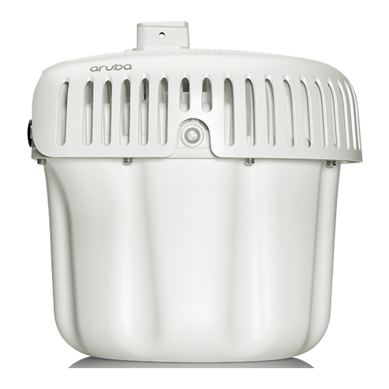
Aruba 580 Series Outdoor Access Points
Installation Guide
The Aruba 580 Series outdoor wireless access points (AP-584, AP-585 and AP-587) support the IEEE 802.11ax
standard, delivering high performance with the MIMO (Multiple-Input, Multiple-Output) and OFDMA (Orthogonal
Frequency Division Multiple Access) technologies, while also supporting 802.11a/b/g/n/ac wireless services.
Package Contents
580 Series access point
M20 cable gland x 2
USB Type-C console cable x 1
Ground lug kit x 1
2.4GHz Vpol N-type BLE antenna x 1 (AP-584 only)
Tools Required
Phillips screwdriver (#2 for M4x6 screw)
Flat blade screwdriver (for Ethernet port cap)
8mm Allen or hex key (for USB console cap)
The weatherproof caps for Ethernet, AC and Console interfaces are connected to the access point, not loose in
the package.
Mounting kits for use with the 580 Series access points are sold separately. Contact your Aruba sales
representative for details.
Inform your supplier if there are any incorrect, missing, or damaged parts. If possible, retain the carton,
including the original packing materials. Use these materials to repack and return the unit to the supplier if
needed.
Rev 01 | March 2022
1
Advertisement
Table of Contents

Related Manuals for Aruba Networks AP-580 Series


Summary of Contents for Aruba Networks AP-580 Series
- Page 1 Aruba 580 Series Outdoor Access Points Installation Guide The Aruba 580 Series outdoor wireless access points (AP-584, AP-585 and AP-587) support the IEEE 802.11ax standard, delivering high performance with the MIMO (Multiple-Input, Multiple-Output) and OFDMA (Orthogonal Frequency Division Multiple Access) technologies, while also supporting 802.11a/b/g/n/ac wireless services. Package Contents 580 Series access point ...
-
Page 2: Hardware Overview
Hardware Overview AP-584 Front View (with Aesthetic Cover) Figure 1 The antenna connectors of the AP-584 are covered by an aesthetic cover. The aesthetic cover can be removed when necessary. If leaving the cover in place, be careful not to exceed the antenna cable bend radius, or use proper angled connector cables to minimize cable bends. - Page 3 AP-585 Front View Figure 3 AP-585 Rear View Figure 4 USB Console Port, Reset Button and Grounding Point AC Power Port E1/SFP+ E2/PSE E0/PoE+ | Installation Guide Aruba 580 Series Outdoor Access Points...
-
Page 4: External Antenna Connectors
AP-587 Front View Figure 5 AP-587 Rear View Figure 6 USB Console Port, Reset Button and AC Power Port E1/SFP+ E2/PSE E0/PoE+ Grounding Point External Antenna Connectors The AP-584 access point comes with four external Wi-Fi antenna connectors and one external BLE antenna connector. - Page 5 External antennas for this device must be installed by an Aruba Certified Mobility Professional (ACMP) or other Aruba-certified technician, using manufacturer-approved antennas only. The Equivalent Isotropically Radiated Power (EIRP) levels for all external antenna devices must not exceed the regulatory limit set by the host country/domain. Installers are required to record the antenna gain for this device in the system management software.
-
Page 6: Ethernet Ports
580 Series LED Meanings during Boot Up Table 1 Color/State Meaning System LED No power to AP Initial power-up Flashing - Green AP booting, not ready On - Green AP ready. GbE (or better) or SFP+ connected. The LED turns off after 1200 seconds Green - Yellow, 6 seconds AP ready. -
Page 7: Before You Begin
USB Type-C Console Port Use the included USB Type-C console cable to connect the access point to a laptop or a serial terminal for direct management. Use an 8mm Allen or hex key to open the cover of the USB Console port. Reset Button The reset button can be used to reset the access point to factory default settings or turn off/on the LED display. -
Page 8: Outdoor Planning And Deployment Considerations
Outdoor Planning and Deployment Considerations Prior to deploying an outdoor wireless network, the environment must be evaluated to plan for a successful WLAN deployment. Successfully evaluating the environment enables the proper selection of access points and antennas and assists in the determination of their placement for optimal RF coverage. This process is considered WLAN or RF planning and Aruba’s system engineers can assist in the outdoor planning process. -
Page 9: Using Mount Kits
Using Mount Kits The 580 Series access point can be installed on a wall or attached to a pole by using mount kits: Applicable Mount Kits for 580 Series Access Point Table 3 Part Number Description Supported Model R9H97A AP-OUT-MNT-V1A Aruba Outdoor AP Pole/ AP-584/AP-585: Wall or Pole Wall Long Mount Kit. - Page 10 Ethernet Cable and M20 Cable Gland Assembly Figure 8 Ethernet Cable O-ring Gland Body Seals Clip Sealing Nut 1. Remove the dust cap from the Ethernet port 2. Slide the sealing nut, clip, gland body and O-ring over the cable. 3.
-
Page 11: Connecting The Fiber-Optic Cable
Ethernet Cable and M20 Cable Gland Installed to AP Figure 9 Connecting the Fiber-optic Cable The fiber-optic cable is not included in the package and must be purchased separately. Purchase a suitable 6- 12 mm diameter, UV-resistant, outdoor rated cable for use with the access point. The CKIT-OD-SFP SFP cable gland is not included in the package and must be purchased separately, refer to the 580 Series ordering guide on the Aruba website https://www.arubanetworks.com. -
Page 12: Connecting The Ac Power Cable
3. Slide the sealing nut, clip, seals and gland body over the fiber-optic cable. 4. Insert the connector of the fiber-optic cable into the transceiver module, and ensure the connector is firmly in place. 5. Thread the gland body into the E1 SFP+ port on the AP and tighten to a torque of 45 in/lbs (5.0 Nm). 6. - Page 13 The required specifications for third party cable used with the AP-AC-MLX outdoor Molex AC connector kit are as follows: AC power cable specifications: UV-resistant, outdoor-rated three-wire AC cable (18 AWG) with outside cable diameter of 6-12mm and inside wire diameter no more than 3.1mm Connecting the AC Power Cable To connect the AC power cable to the access point, assemble the AC power cable as instructed in the installation guide of the AP-AC-MLX outdoor AC connector kit (sold separately), and then perform the following steps using...
-
Page 14: Verifying Post-Installation Connectivity
5. Thread the gland body into the AC power port and tighten to a torque of 10.6 in/lbs (1.2 Nm). 6. Combine the two split seals over the cable, and push towards the gland body until located at the recess of the gland body. -
Page 15: Regulatory Model Number
E2 PSE port: 100/1000Base-T auto-sensing MDI/MDI-X wired network port (RJ45). The AP supports 802.3af PoE-Out when PoE powered, and supports up to 802.3at when powered by AC. Environmental Operating Temperature: -40ºC to 65ºC (-40ºF to 149ºF) If the 580 Series access point is deployed supporting Fiber, PSE, and high user loads in extremely hot temperatures or in hot environments with large solar loading environments, it is strongly recommended to enable Intelligent Power and Temperature Monitoring (IPTM) to ensure continuous uninterrupted operations, allowing the AP to disable specific and user-definable features to ensure continuity and prevent a thermal... -
Page 16: Innovation, Science And Economic Development Canada
Toute modification effectuée sur cet équipement sans l'autorisation expresse de la partie responsable de la conformité est susceptible d'annuler son droit d'utilisation. United States This equipment has been tested and found to comply with the limits for a Class B digital device, pursuant to Part 15 of the FCC Rules. -
Page 17: European Union Regulatory Conformance
dessous) avec le gain maximal admissible indiqué. Les types d'antennes non inclus dans cette liste, ayant un gain supérieur au gain maximal indiqué pour ce type, sont strictement interdits pour une utilisation avec cet appareil. https://www.arubanetworks.com/assets/og/OG_AP-580Series.pdf European Union Regulatory Conformance The Declaration of Conformity made under Radio Equipment Directive 2014/53/EU is available for viewing at: www.hpe.com/eu/certificates. -
Page 18: Нормативные Требования Евразийского Экономического Союза
Brazil Este equipamento não tem direito à proteção contra interferência prejudicial e não pode causar interferência em sistemas devidamente autorizados. Japan México La operación de este equipo está sujeta a las siguientes dos condiciones: (1) es posible que este equipo o dispositivo no cause interferencia perjudicial y (2) este equipo o dispositivo debeaceptar cualquier interferencia, incluyendo la que pueda causar su operación no deseada. -
Page 19: Contact Aruba
Contact Aruba Main Site https://www.arubanetworks.com Support Site https://asp.arubanetworks.com Airheads Social Forums and Knowledge Base https://community.arubanetworks.com/ North America Telephone 1-800-943-4526 1-408-754-1200 International Telephone https://www.arubanetworks.com/support-services/contact-support/ Software Licensing Site https://www.hpe.com/networking/support End-of-Life Information https://www.arubanetworks.com/support-services/end-of-life/ Security Incident Response Team (SIRT) https://www.arubanetworks.com/support-service/security-bulletins/ Email: aruba-sirt@hpe.com Copyright © Copyright 2022 Hewlett Packard Enterprise Development LP Open Source Code This product includes code licensed under the GNU General PublicLicense, the GNU Lesser General Public License, and/or certain other open source licenses.
Need help?
Do you have a question about the AP-580 Series and is the answer not in the manual?
Questions and answers