Table of Contents
Advertisement
AP-175-IG-Rev01.fm Page 1 Friday, September 17, 2010 4:27 PM
Aruba AP-175 Outdoor Access Point
Installation Guide
The Aruba AP-175 is a resilient, environmentally hardened, outdoor rated, dual-radio, dual-band IEEE
802.11 a/b/g/n wireless access point. This outdoor access point is part of Aruba's comprehensive wireless
network solution. The AP-175 works only in conjunction with an Aruba controller and each AP can be
centrally managed, configured, and upgraded through the controller.
There are three versions of the AP-175, which mainly differ in the way they receive power.
AP-175P: PoE+ powered (802.3at)
AP-175AC: AC powered (100 - 240 VAC)
AP-175DC: DC powered (12 - 48 VDC)
The AP-175AC/DC can function as a Power Sourcing Equipment (PSE) device by providing power through its
Ethernet port in compliance with the IEEE 802.3af standard.
N O T E
Guide Overview
"AP-175 Hardware Overview" on page 2
models.
"Outdoor Planning and Deployment Considerations" on page 5
to consider when deploying an outdoor wireless network.
"Installing the AP-175" on page 9
deployment of an AP-175.
"Safety and Regulatory Compliance" on page 15
compliance information.
AP-175 Operations
Wireless access point (IEEE 802.11 a/b/g/n)
Wireless air monitor (IEEE 802.11 a/b/g/n)
Enterprise mesh point
Enterprise mesh portal
Protocol-independent networking functionality
AP-175P: IEEE 802.3at Power over Ethernet+ (PoE+) compatible
AP-175AC and AP-175DC: IEEE 802.3af Power Sourcing Equipment (PSE) device
0510795-01
| September 2010
provides a detailed hardware overview of the three AP-175
describes the multi-step process for a successful installation and
provides an overview of safety and regulatory
provides key questions to ask and items
1
Advertisement
Table of Contents

Related Manuals for Aruba Networks AP-175DC


Summary of Contents for Aruba Networks AP-175DC
- Page 1 Wireless access point (IEEE 802.11 a/b/g/n) Wireless air monitor (IEEE 802.11 a/b/g/n) Enterprise mesh point Enterprise mesh portal Protocol-independent networking functionality AP-175P: IEEE 802.3at Power over Ethernet+ (PoE+) compatible AP-175AC and AP-175DC: IEEE 802.3af Power Sourcing Equipment (PSE) device 0510795-01 | September 2010...
-
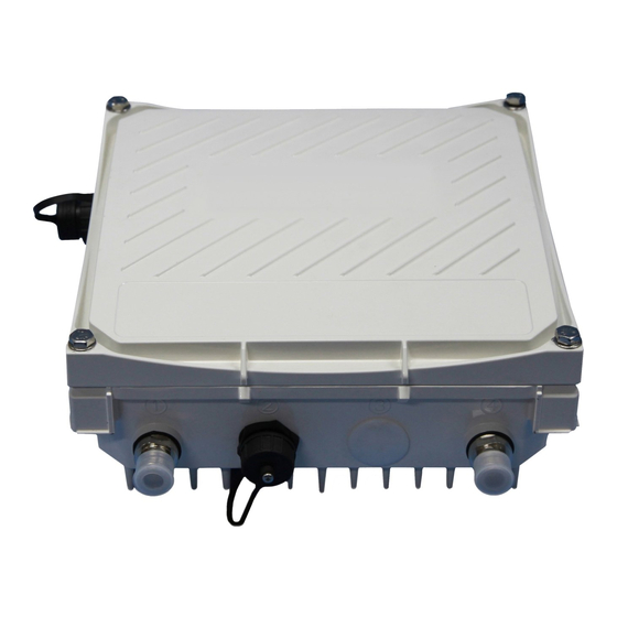
Page 2: Package Contents
Antenna Interface (Radio 1) Antenna Interface (Radio 0) USB Console Interface Antenna Interface (Radio 1) Reserved (AP-175P) or Ethernet Interface (PoE) Power Interface (AP-175AC and AP-175DC) Antenna Interface (Radio 0) Grounding Point Aruba AP-175 Outdoor Access Point | Installation Guide... - Page 3 (PD) from a power sourcing equipment (PSE) device, such as a PoE midspan injector. Inversely, the AP-175AC and AP-175DC can act as a PSE device to provide IEEE802.3af PoE power to devices connected to the Ethernet port.
- Page 4 AP-175-IG-Rev01.fm Page 4 Friday, September 17, 2010 4:27 PM Figure 2 LED Layout RSSI for Radio 0 RSSI for Radio 1 Table 2 lists the meanings of the LEDs on the AP-175 outdoor access points. Table 2 AP-175 LED Status Indicators Function Indicator Status...
-
Page 5: Outdoor Planning And Deployment Considerations
AP-175-IG-Rev01.fm Page 5 Friday, September 17, 2010 4:27 PM Outdoor Planning and Deployment Considerations Prior to deploying an outdoor wireless network, the environment must be evaluated to plan for a successful Aruba WLAN deployment. Successfully evaluating the environment enables the proper selection of Aruba APs and antennas and assists in the determination of their placement for optimal RF coverage. -
Page 6: Antenna Height
AP-175-IG-Rev01.fm Page 6 Friday, September 17, 2010 4:27 PM radio signal power travels. This area is known as the first Fresnel Zone of the radio link. For a radio link, no object (including the ground) must intrude within 60% of the first Fresnel Zone. Figure 3 illustrates the concept of a good radio line of sight. - Page 7 AP-175-IG-Rev01.fm Page 7 Friday, September 17, 2010 4:27 PM Table 3 Antenna Minimum Height and Clearance Requirements Max Clearance for Total Clearance Approximate Clearance Total Link Distance 60% of First Fresnel Required at for Earth Curvature Zone at 5.8 GHz Mid-point of Link 1 mile (1.6 km) 8.9 ft (2.7 m)
-
Page 8: Antenna Position And Orientation
AP-175-IG-Rev01.fm Page 8 Friday, September 17, 2010 4:27 PM Local regulations may limit or prevent construction of a high radio mast or tower. If your wireless bridge or mesh link requires a high radio mast or tower, consult a professional contractor for advice. N O T E Antenna Position and Orientation Once the required antenna height has been determined, other factors affecting the precise position of the... -
Page 9: Installing The Ap-175
AP-175-IG-Rev01.fm Page 9 Friday, September 17, 2010 4:27 PM Ethernet Cabling When a suitable antenna location has been determined, you must plan a cable route from the wireless bridge or mesh link outdoors to a suitable power and/or network source. Consider these points: The Ethernet cable length should never be longer than 90 m (295 ft). - Page 10 AP-175-IG-Rev01.fm Page 10 Friday, September 17, 2010 4:27 PM Figure 5 Attaching the mounting bracket to the AP 2. Attach the mounting bracket (with AP-175) on the pole using four M8 x110 bolts (with flat washers, spring washers and nuts) and the pair of pole anchors. Figure 6 Attaching the mounting bracket to the pole Aruba AP-175 Outdoor Access Point | Installation Guide...
-
Page 11: Installing The Ap-175 On A Wall
AP-175-IG-Rev01.fm Page 11 Friday, September 17, 2010 4:27 PM Installing the AP-175 on a Wall 1. Begin by marking the screw points on the wall in the location you have selected. a. Put the mounting bracket on the installation position against the wall. b. -
Page 12: Grounding The Ap-175
AP-175-IG-Rev01.fm Page 12 Friday, September 17, 2010 4:27 PM Figure 8 Attaching the AP to the Mounting Bracket Grounding the AP-175 The grounding must be completed before powering up the AP-175. The resistance of grounding wire should be less than 5 ohm and the grounding cable’s cross-section area should be no less than 6 mm.The grounding hole is at the right side of the AP-175. -
Page 13: Connecting The Ethernet Cable
AP-175-IG-Rev01.fm Page 13 Friday, September 17, 2010 4:27 PM Connecting the Ethernet Cable 1. Remove the protective cap on the Ethernet interface. 2. Attach the waterproof Ethernet connector to the Ethernet cable. Figure 10 Waterproof Ethernet Connector Cover Shielded RJ45 connector Locknut Gasket Mat Seal Ring... - Page 14 AP-175-IG-Rev01.fm Page 14 Friday, September 17, 2010 4:27 PM Figure 12 Attaching the Solar Shield to the AP Aruba AP-175 Outdoor Access Point | Installation Guide...
-
Page 15: Safety And Regulatory Compliance
AP-175-IG-Rev01.fm Page 15 Friday, September 17, 2010 4:27 PM Safety and Regulatory Compliance Aruba Networks provides a multi-language document that contains country-specific restrictions and additional safety and regulatory information for all Aruba access points. This document can be viewed or downloaded from the following location: www.arubanetworks.com/safety_addendum... -
Page 16: European Union Rohs
AP-175-IG-Rev01.fm Page 16 Friday, September 17, 2010 4:27 PM European Union RoHS Aruba products also comply with the EU Restriction of Hazardous Substances Directive 2002/95/EC (RoHS). EU RoHS restricts the use of specific hazardous materials in the manufacture of electrical and electronic equipment. Specifically, restricted materials under the RoHS Directive are Lead (including Solder used in printed circuit assemblies), Cadmium, Mercury, Hexavalent Chromium, and Bromine. - Page 17 AP-175-IG-Rev01.fm Page 17 Friday, September 17, 2010 4:27 PM Aruba AP-175 Outdoor Access Point | Installation Guide...
- Page 18 AP-175-IG-Rev01.fm Page 18 Friday, September 17, 2010 4:27 PM Aruba AP-175 Outdoor Access Point | Installation Guide...
- Page 19 AP-175-IG-Rev01.fm Page 19 Friday, September 17, 2010 4:27 PM Aruba AP-175 Outdoor Access Point | Installation Guide...
-
Page 20: Contacting Aruba Networks
The use of Aruba Networks, Inc. switching platforms and software, by all individuals or corporations, to terminate other vendors' VPN client devices constitutes complete acceptance of liability by that individual or corporation for this action and indemnifies, in full, Aruba Networks, Inc. from any and all legal actions that might be taken against it www.arubanetworks.com with respect to infringement of copyright on behalf of those vendors.
Need help?
Do you have a question about the AP-175DC and is the answer not in the manual?
Questions and answers