Table of Contents
Advertisement
Quick Links
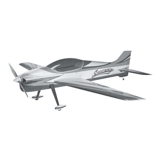
Wingspan: 71.5 in [1815 mm]
Wing Area: 836 in
Wing Loading: 27−30 oz/ft
Length: 73 in [1855 mm]
WARRANTY
Great Planes Model Manufacturing
be free from defects in both material and workmanship at the
date of purchase. This warranty does not cover any component
parts damaged by use or modification. In no case shall Great
Planes' liability exceed the original cost of the purchased kit.
Further, Great Planes reserves the right to change or modify this
warranty without notice.
In that Great Planes has no control over the final assembly or
material used for final assembly, no liability shall be assumed nor
accepted for any damage resulting from the use by the user of
the final user-assembled product. By the act of using the
user-assembled product, the user accepts all resulting liability.
If the buyer is not prepared to accept the liability associated
with the use of this product, the buyer is advised to return
READ THROUGH THIS MANUAL BEFORE STARTING CONSTRUCTION. IT CONTAINS IMPORTANT
INSTRUCTIONS AND WARNINGS CONCERNING THE ASSEMBLY AND USE OF THIS MODEL.
© 2014 Great Planes Model Mfg. A subsidiary of Hobbico, Inc.
Weight: 9.75− 10.75 lb
2
2
[53.9 dm
]
Radio: 4– 6 channel
2
2
[82− 92 g /dm
]
®
Co. guarantees this kit to
INSTRUCTION MANUAL
[4420 − 4870 g]
this kit immediately in new and unused condition to the
place of purchase.
To make a warranty claim send the defective part or item to
Hobby Services at the address below:
3002 N. Apollo Dr. Suite 1
Champaign IL 61822 USA
Include a letter stating your name, return shipping address, as
much contact information as possible (daytime telephone
number, fax number, e-mail address), a detailed description of
the problem and a photocopy of the purchase receipt. Upon
receipt of the package the problem will be evaluated as quickly
as possible.
™
SPECIFICATIONS
Engine: 1.20 cu in [20cc] 2-stroke glow,
1.55 cu in [25cc] 4-stroke glow,
Rimfire 1.20 Brushless
electric
Hobby Services
Champaign, Illinois
(217) 398-8970, Ext 5
airsupport@greatplanes.com
GPMA1232
Advertisement
Table of Contents

Related Manuals for GREAT PLANES Sequence 1.20


Summary of Contents for GREAT PLANES Sequence 1.20
-
Page 1: Instruction Manual
3002 N. Apollo Dr. Suite 1 Champaign IL 61822 USA In that Great Planes has no control over the final assembly or material used for final assembly, no liability shall be assumed nor Include a letter stating your name, return shipping address, as... -
Page 2: Table Of Contents
INTRODUCTION ....... . 2 Sequence 1.20 ARF! The Sequence may not have all of the SAFETY PRECAUTIONS . -
Page 3: Safety Precautions
The 50-65-450kV RimFire 1.20 powered by a 5,000mAh 6S 5. If you are not an experienced pilot or have not fl own this type battery and APC 17 x 8E propeller fl ies the Sequence 1.20 of model before, we recommend that you get the assistance nicely. -
Page 4: Radio Equipment
(WSDM3001) ❍ Futaba Switch Harness (FUTM4370) ❍ Electrical solder, soldering fl ux, soldering iron ❍ Great Planes 3"[75mm] double-sided servo arm (for the rudder servo, GPMM1165) LIPO BATTERY CHARGER REQUIREMENTS A LiPo-compatible battery charger with cell balancing is required. -
Page 5: Kit Inspection
Parts List that follows. The fastest, most economical service can be provided by your hobby dealer or mail-order company. To locate a hobby dealer, visit the Great Planes web site at greatplanes.com. Choose “Where to Buy” at the upper right side of the page. -
Page 6: Assemble The Wings
ASSEMBLE THE WINGS ❏ 4. Use thin CA followed by a small fi llet of medium CA to reinforce the servo mounting blocks to the hatch covers. ❏ 1. Pull hard on the ailerons to test the hinges. Inspect the ❏... - Page 7 14. Guide the aileron servo wires out the end of the wing servo arms, if using the and mount the hatch covers with four #2 x 3/8" [9.5mm] included Great Planes button-head screws—do not use a ball-end hex wrench. 4-40 ball links, enlarge Use a quality, machine-ground hex driver.
-
Page 8: Assemble The Fuselage
CAUTION: The turtledeck and fuselage bottom of the 4-40 Pushrod Threaded Coupler Sequence 1.20 are made from balsa-covered foam. Some solvents and adhesives will attack the foam, so use ❏ 15. Make the aileron pushrod from a 4-40 x 4-1/2" [115mm] care—especially when using CA which will defi... -
Page 9: Prepare The Fuselage For Mounting The Engine (Or Electric Motor)
4-40x3/8" [10mm] Phillips #6 Washers Prepare the Fuselage for Mounting and #4 Flat Washers (as spacers) 6-32" Set Screw the Engine (or Electric Motor) 5-32" [4mm] Wheel Collar Fiberglass Wheel Pant ❏ 4. Mount the wheels and wheel pants as shown—don’t forget to use threadlocker on all the screws. -
Page 10: Mount A Glow Engine
If mounting the Great Planes Brushless Motor Mount a Glow Engine Mount for Large Motors drill the holes through the fi rewall at the four angled tick marks. If mounting the optional wood Refer to this photo for the following two steps. -
Page 11: Hook Up The Throttle
Hook Up the Throttle Install the Fuel Tank ❏ 1. Refer to following photos to see which of the two throttle servo mounting locations will work best for your engine. Cut the side or bottom servo mount hole from the location you will use. -
Page 12: Mount An Electric Motor
Mount an Electric Motor Before mounting the motor and setting up the ESC and battery, read the following important battery precautions: IMPORTANT: If using multiple battery packs that are connected with an adapter, never charge the batteries together through the adapter. Always charge each battery pack separately. Charge the batteries, then read the following precautions on how to connect multiple packs for fl... - Page 13 11.1V (3-Cell) 1250mAh ❏ 4. If using the Great Planes ElectriFly 80A ESC, install Also NEVER connect battery packs with different capacities Great Planes 6mm male/4mm female bullet adapters in Series or in Parallel. (GPMM3119) on the motor wires, or remove the 6mm female bullet connectors from the ESC and solder on 4mm female bullet connectors (GPMM3115) instead.
- Page 14 SHCS, #8 lock washers and fl at washers and threadlocker. How to Make an Externally-Accessible Arming Plug: ❏ 7. Before mounting the ESC consider the options for ❏ A. First, you’ll need a connecting the battery. First, the wires coming from the ESC short metal tab to bridge the are probably not long enough to reach the battery, so an tabs across a Deans male...
- Page 15 ❏ 10. If using the arming plug, carefully cut the covering side of Great Planes adhesive Velcro to the battery fl oor and from the side of the fuselage over the location you will use for apply strips of the softer, “loop” side to the batteries. Then the receptacle.
-
Page 16: Cut The Cowl
template aligns with the bottom of the cowl “cheek” and the Cut the Cowl back of the template aligns with the back of the cowl. Use a fi ne-point felt-tip pen to mark the cutout directly onto the cowl. If going electric the cowl probably doesn’t need to be cut—just skip ahead to “Mount the Cowl”... - Page 17 ❏ 5. Test fi t the cowl and see where it needs to be cut next. Mark the inside again if necessary, or switch to a fi ne-point felt-pen to mark the outside. Remove the cowl and continue to cut in small increments. ❏...
-
Page 18: Mount The Cowl
If using the cowl ring, fi rst make an extended hex driver… ❏ A. Use a Dremel with a fi ber-reinforced cutoff wheel to cut a Great Planes 3/32" Hex driver ball wrench in half. Then ❏ 2. Press two 4-40 blind nuts into the front of the top two cut a 4"... - Page 19 ❏ 6. Once satisfi ed with the fi t of the cowl ring, re mount it to the fuselage with the screws. ❏ 7. Use coarse sandpaper to roughen the cowl all the way around the inside so glue will adhere. “Prime” the inside of the cowl with a few squirts of CA accelerator to keep the CA from leaking around the cowl ring inadvertently gluing it to the fuselage.
- Page 20 ❏ ❏ 10. Medium CA will be used to glue the cowl to the cowl 14. Securely glue the back of the cowl ring with thin CA ring, but you’ll need an extended glue tip in order to reach and the front of the cowl ring with medium CA. down inside.
-
Page 21: Mounting The Cowl With Wood Screws
METHOD 2: Mounting the Cowl with Wood Screws In the following steps it may be helpful to have an assistant drill the holes while you hold the cowl… Hard point Hard point ❏ ❏ D. Holding the cowl in position, use one of the templates A. -
Page 22: Finish The Cowl
4-40x1/2" Threaded SHCS Cable Coupler 4-40 Ball Link Stand-Off Great Planes Brass 3" Double-Side Cable Swage Servo Arm ❏ 1. If using a glow engine, mount the muffl er and make any additional cuts necessary—you may have to cut through the cowl ring, but this won’t weaken the cowl because the ring... - Page 23 ❏ place. Mount the rudder servo and hook up the rudder using 10. Fit both stabilizer halves to the fuselage with the the hardware shown—be certain to use threadlocker on all aluminum joiner tube as you guide the servo wires down the 4-40 nuts and don’t forget to harden the servo mounting through the fuselage—a long piece of wire with a hook bent screw holes with thin CA.
-
Page 24: Final Assembly
(including the ❏ 4. Use a Great Planes C.G. Machine or lift the model motor battery positioned in the approximate location shown with your fi ngers at the balance point. Position the receiver in previous photos if using an electric motor). -
Page 25: Balance The Model Laterally
Balance the Model Laterally PREFLIGHT ❏ 1. With the wing level, lift the model under the tail and by Identify Your Model the propeller shaft. Do this several times. Always attach your name, address, telephone number and ❏ 2. If one wing always drops when you lift the model, it AMA number somewhere on or inside your model. -
Page 26: Range Check
For the Sequence 1.20 for example, say we record a 6 Use a “chicken stick” or electric starter to start the engine. minute fl ight. And back in the shop we record that the battery Do not use your fi... -
Page 27: Ama Safety Code (Excerpts)
Make all engine adjustments from behind the rotating 4) I will operate my model using only radio control frequencies propeller. currently allowed by the Federal Communications Commission. The engine gets hot! Do not touch it during or right after 5) I will not knowingly operate my model within three miles operation. -
Page 28: Flying
FLYING There are no particular fl ight characteristics about the Sequence 1.20 that you need to be made aware of ahead of time. The Sequence is a well-balanced, neutral fl ying plane that will go wherever you point it. Simply fl y the Sequence within your capabilities and take it easy for the fi... - Page 29 to drill 1/16 " [1.6mm] pilot holes through the FRP motor mount plate. If using a different motor, mark, then drill holes to fi t your motor. Hint: For perfection, fasten the template to the mount with 4-40 screws and nuts. 5/16"...
- Page 30 12. Rejoin the assembly manual at Mount an Electric Motor on page 13. Note: The spinner back plate will have to be enlarged with a 3/8 " [9.5mm] drill for the Great Planes propeller adapter. 10. Drill 7/32 " [5.6m] holes through the fi rewall at the four “+”...
Need help?
Do you have a question about the Sequence 1.20 and is the answer not in the manual?
Questions and answers