Table of Contents
Advertisement
Quick Links
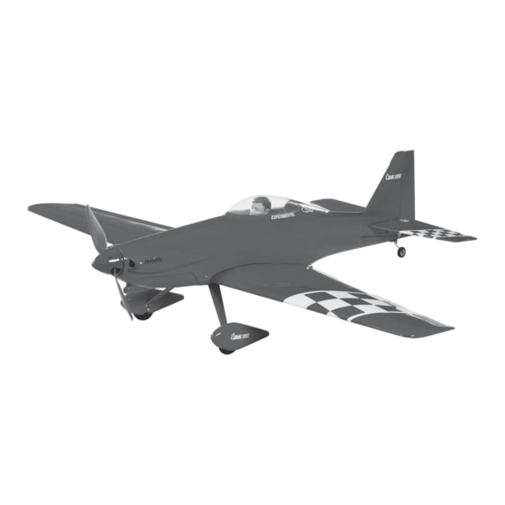
SPECIFICATIONS
Wingspan: 35.75 in [908mm]
Wing Area: 254 in
Wing Loading: 15.5−16.5 oz/ft
WARRANTY
Great Planes
®
Model Manufacturing Co. guarantees this kit to
be free from defects in both material and workmanship at the
date of purchase. This warranty does not cover any component
parts damaged by use or modification. In no case shall Great
Planes' liability exceed the original cost of the purchased kit.
Further, Great Planes reserves the right to change or modify this
warranty without notice.
In that Great Planes has no control over the final assembly or
material used for final assembly, no liability shall be assumed nor
accepted for any damage resulting from the use by the user of
the final user-assembled product. By the act of using the
user-assembled product, the user accepts all resulting liability.
If the buyer is not prepared to accept the liability associated
with the use of this product, the buyer is advised to return
READ THROUGH THIS MANUAL BEFORE STARTING CONSTRUCTION. IT CONTAINS IMPORTANT
INSTRUCTIONS AND WARNINGS CONCERNING THE ASSEMBLY AND USE OF THIS MODEL.
®
Entire Contents © 2011 Hobbico,
Inc. All rights reserved.
2
2
[16.4 dm
]
2
2
[47−50 g /dm
]
INSTRUCTION MANUAL
Length: 32 in [813mm]
Weight: 27.5 − 29.5 oz [779−836 g]
Radio: 4-channel radio
this kit immediately in new and unused condition to the
place of purchase.
To make a warranty claim send the defective part or item to
Hobby Services at the address below:
Include a letter stating your name, return shipping address, as
much contact information as possible (daytime telephone
number, fax number, e-mail address), a detailed description of
the problem and a photocopy of the purchase receipt. Upon
receipt of the package the problem will be evaluated as quickly
as possible.
Motor: RimFire
Hobby Services
3002 N. Apollo Dr. Suite 1
Champaign IL 61822 USA
Champaign, Illinois
(217) 398-8970, Ext 5
airsupport@greatplanes.com
™
.10
GPMA1810 / GPMA1811 Mnl
Advertisement
Table of Contents

Related Manuals for GREAT PLANES Cosmic Wind


Summary of Contents for GREAT PLANES Cosmic Wind
-
Page 1: Instruction Manual
3002 N. Apollo Dr. Suite 1 Champaign IL 61822 USA In that Great Planes has no control over the final assembly or material used for final assembly, no liability shall be assumed nor Include a letter stating your name, return shipping address, as... -
Page 2: Table Of Contents
Academy of Model Aeronautics AirVenture Museum in Oshkosh, Wisconsin. Great Planes 5151 East Memorial Drive has taken the great looks of the full scale Cosmic Wind and Muncie, IN 47302-9252 reduced it down to a light weight, electric powered ARF. The Tele. -
Page 3: Decisions You Must Make
Flight Battery work area thoroughly after working with fi berglass parts. The Cosmic Wind EP ARF has been fl own with the ElectriFly We, as the kit manufacturer, provide you with a top quality, Power Series 11.1V 1500mAh LiPo battery and the Flight thoroughly tested kit and instructions, but ultimately the ™... -
Page 4: Additional Items Required
This is the list of adhesives and building supplies required your experience to decide what type of glue to use. When to finish the Cosmic Wind EP. Order numbers are provided a specifi c type of adhesive works best for that step, the in parentheses. -
Page 5: Ordering Replacement Parts
ORDERING REPLACEMENT PARTS Product Support by e-mail at productsupport@greatplanes. com, or by telephone at (217) 398-8970. Replacement parts for the Great Planes Cosmic Wind EP are available using the order numbers in the Replacement For GPMA1810 Cosmic Wind EP ARF Parts List that follows. -
Page 6: Preparations
❏ 3. Mix together ½ oz. [15cc] of 30-minute epoxy. Coat the PREPARATIONS inside of wing joiner cavity in both of the wing halves. Apply ❏ epoxy to half of the wing joiner and insert it into one of the 1. -
Page 7: Assemble The Fuselage
ASSEMBLE THE FUSELAGE Install the Main Landing Gear ❏ ❏ 3. Position the right wheel pant over the wheel and secure it to the main landing gear with two 2 × 5 mm self tapping screws. ❏ ❏ 4. Attach the main landing gear to the fuselage with three 2.5 ×8mm self tapping screws. - Page 8 HOW TO CUT COVERING FROM BALSA Use a soldering iron to cut the covering from the stabilizer. The tip of the soldering iron doesn’t have to be sharp, but a fi ne-tip does work best. Allow the iron to heat fully. ❏...
-
Page 9: Install The Elevators And Rudder
The gap should be small, just enough to see light Install the Motor through or to slip a piece of paper through. The Cosmic Wind EP has been designed to use the ElectriFly ❏ 3. Apply four drops of thin CA to the top and bottom of each RimFire .10 Outrunner Brushless motor. -
Page 10: Install The Radio System
❏ 4. Use adhesive backed hook and loop material to mount the receiver to the side of the fuselage. Tape the two antennas to the sides of fuselage. If using a 72 MHz receiver, route the antenna out the cooling exit holes and tape it to the bottom ❏... - Page 11 ❏ 3. Using the elevator pushrod wire, position the control horn so that the four pushrod holes are in line with the elevator hinge line. Mark the location of the mounting holes onto the elevator. Drill a 3/32" [2.5 mm] hole on the marks, drilling through the elevator.
-
Page 12: Install The Rudder Servo
❏ 2. Glue the aileron servo tray over the aileron servo opening. Install the Rudder Servo ❏ 3. Remove the rubber aileron torque rod thread protectors. Thread an aileron torque rod horn on to both aileron torque rods so that the threads are fl ush with the top of the torque rod horns. -
Page 13: Finish The Model
❏ 2. Cut and attach several pieces of the included adhesive ❏ backed hook or loop material to the top of the battery tray. 6. Apply a drop of threadlocker to the threads of four cap Attach the opposite piece of the hook and loop material to screws. -
Page 14: Apply The Decals
❏ 1. Use scissors or a sharp hobby knife to cut the decals To ensure a successful fi rst fl ight, set up your Cosmic Wind from the sheet. EP according to the control throws specifi ed in this manual. -
Page 15: Install The Propeller
distance the elevator moves up from center is the “up” elevator throw. Measure the down elevator throw the same way. ❏ 4. Measure and set the low rate elevator throws and the high and low rate throws for the rest of the control surfaces the same way. -
Page 16: Balance The Model Laterally
❏ 1. With the wing level, have an assistant help you lift the (TOPQ5700) in the workshop and keep a Great Planes model by the engine propeller shaft and the bottom of the Fingertip Prop Balancer (GPMQ5000) in our fl ight box. -
Page 17: Motor Safety Precautions
antenna. The antenna should be as far away from the ESC 5) I will not fl y my model unless it is identifi ed with my name and battery as possible. and address or AMA number, on or in the model. Note: This does not apply to models while being fl... -
Page 18: Flying
R/C Take it easy with the Cosmic Wind EP for the fi rst fl ight, trainer and should be fl own only by experienced R/C pilots. gradually getting acquainted with it as you gain confi dence. - Page 19 the wind) keeping the nose down to maintain airspeed and are on the desired rates (high/low rates). A fl ight plan greatly control. Level the attitude when the model reaches the runway reduces the chances of crashing your model just because threshold, modulating the throttle as necessary to maintain of poor planning and impulsive moves.
Need help?
Do you have a question about the Cosmic Wind and is the answer not in the manual?
Questions and answers