Table of Contents
Advertisement
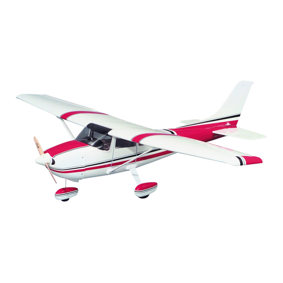
Wing Span - 62-5/8 in
Wing Area - 577 sq in
Weight - 6 lbs
Wing Loading - 24 oz/sq in
Fuse Length - 47 in
Engine - .40 - .46 2-stroke, .52 4-stroke
Great Planes
Model Manufacturing Co. guarantees this kit to be free from defects in both material and workmanship at the date of
®
purchase. This warranty does not cover any component parts damaged by use or modification. In no case shall Great Planes' liability
exceed the original cost of the purchased kit. Further, Great Planes reserves the right to change or modify this warranty without
notice.
In that Great Planes has no control over the final assembly or material used for final assembly, no liability shall be assumed nor
accepted for any damage resulting from the use by the user of the final user-assembled product. By the act of using the user-
assembled product, the user accepts all resulting liability.
If the buyer is not prepared to accept the liability associated with the use of this product, the buyer is advised to return this
kit immediately in new and unused condition to the place of purchase.
While this kit has been flight tested to exceed normal use, if the plane will be used for extremely high stress flying, such as racing, the
modeler is responsible for taking steps to reinforce the high stress points.
READ THROUGH THIS MANUAL BEFORE
STARTING CONSTRUCTION. IT CONTAINS
IMPORTANT WARNINGS AND INSTRUCTIONS
CONCERNING THE ASSEMBLY AND USE OF
THIS MODEL.
© Copyright 2000
INSTRUCTION MANUAL
WARRANTY
P.O. Box 788
Urbana, IL 61803
Cessna is a
registered
trademark of
Cessna Aircraft
Company
(217) 398-8970
GPMZ0219 for GPMA1228 V1.1
Advertisement
Table of Contents

Related Manuals for GREAT PLANES CESSNA 182


Summary of Contents for GREAT PLANES CESSNA 182
-
Page 1: Instruction Manual
In that Great Planes has no control over the final assembly or material used for final assembly, no liability shall be assumed nor accepted for any damage resulting from the use by the user of the final user-assembled product. By the act of using the user- assembled product, the user accepts all resulting liability. -
Page 2: Table Of Contents
2. Take time to build straight, true and strong. 3. Use an R/C radio system that is in first-class condition, Your Cessna 182 ARF is not a toy, but rather a and a correctly sized engine and components (fuel tank, sophisticated, working model that functions very much like a wheels, etc.) throughout your building process. -
Page 3: Decisions You Must Make
Drill Bits: 1/16" [1.5mm], 5/64" [2mm], 3/32" [2.5mm], There are several engines that will work well in your 1/8" [3mm], 5/32" [4mm], 3/16" [5mm], 1/4" [6mm], Cessna 182 ARF. We recommend a 2-stroke such as an 1/2" [13mm] O.S. .40 LA, O.S. .40 FX, O.S. .46 FX, or the ®... -
Page 4: General Inspection
The manual “top” even if the model is being worked on upside-down. begins with all the surfaces shown separated. Your Cessna 182 is covered with high quality Top Flite MonoKote covering. If any of the covering has loosened, ®... -
Page 5: Parts List
Hardware Bag Elevator Assembly (Right & Left) Replacement Parts Rudder Vertical Fin If needed, replacement parts for your Cessna 182 ARF are Wing Center-Section available through your hobby supplier. Wing Dowels Wing Strut Fairing (Left & Right) Wing Kit ..............GPMA2070 Landing Gear Fairing Fuselage Kit ............GPMA2071... -
Page 6: Wing Assembly
WING ASSEMBLY Make a dry run of the following step without using any glue so you will know how to join your wing together, then proceed using glue. ❏ 1. Mark the ailerons left and right and remove them from the wing panels. -
Page 7: Wing Installation
WING INSTALLATION ❏ 2. Mount the wing to the fuselage using the bolts. Stand back 8 to 10 feet [2.5 to 3 meters] and view the model from the front and rear. The stabilizer tips should be equally spaced above the level of the wing. If not, lightly sand the high side of the stab saddle to correct the problem. - Page 8 along both the sides of the fin where it meets the fuselage and remove the covering 1/32" [.8mm] inside the line, being TEMPORARY PIN careful not to cut into the underlying wood. Sand the bottom TO KEEP HINGE CENTERED of the fin and the slot in the fuselage if the fin is out of alignment.
-
Page 9: Engine Installation
❏ 6. Position the engine on the engine mount rails so the propeller thrust washer (or spinner backplate) is 4-7/8" [124mm] ahead of the firewall. Use a Great Planes Dead Center Hole Locator (GPMR8130) (not included) or a ❏ 2. Draw a horizontal line on the firewall 2-3/16" [56mm] sharpened piece of wire to scribe the four engine mount from the top of the fuselage. -
Page 10: Landing Gear Installation
perpendicular to the rails. If you have access to a drill press, the landing gear as shown. Use a felt tip marker and transfer this is a good tool for this purpose. Put a drop of oil into each the location of the hole onto the wheel pant. Remove the hole. -
Page 11: Radio Installation
❏ ❏ 6. Locate the nose gear wire and slide it through the 9. Position a nylon landing gear strap over the nose nose gear block. Adjust the position of the nose gear block gear wire. Mark the locations for the two holes so they will until the nose gear wire is aligned with the centerline of the be over the two pieces of the mixing stick which was glued fuselage. - Page 12 ❏ ❏ 2. Install the rudder, elevator and throttle servos into the 4. Test fit the servo tray into the fuselage. The battery servo tray noting the orientation of the servos. Plug the and receiver are positioned towards the tail of the aircraft battery and servos temporarily into the receiver.
- Page 13 position and mark the location of the mounting holes. Drill 3/32" [2.5mm] mounting holes through the marks. Wick two to three drops of thin CA into the holes to harden the underlying balsa, then re-drill the holes. Attach the horns using four 2-56 x 5/8"...
-
Page 14: Aileron Servo Installation
❏ 17. Insert one of the 2-56 x 36" threaded end rods into the All standard servo horns should fit in the Cessna 182. rudder tube in the fuselage. The pushrod should slide easily into the tube. Thread a nylon clevis on the pushrod 14-turns and add a silicone retainer to the clevis. - Page 15 on your transmitter in the center. This is called “centering” the servos and will allow you to place the servo horns on the servos in a neutral position. Attach the arms to the servos using the following photo. ❏ 1. Trim the covering from the opening in the servo hatches. Position the servos onto the aileron servo hatches so the ❏...
-
Page 16: Steering Pushrod Installation
marks. Wick two to three drops of thin CA into the holes to between the upper and lower sections of the nose gear harden the underlying balsa, then re-drill the holes. Attach block, and slide the nose gear through both sections of the the horns using 2-56 x 3/4"... -
Page 17: Throttle Pushrod Installation
❏ 6" threaded one end rod and one inner pushrod tube. Cut 3. Assemble the throttle pushrod using one nylon clevis, the inner pushrod tube to a length of 6" [152mm]. Cut all but one clevis retainer, one 2-56 x 1" threaded rod, one 2-56 x 6" 1/4"... - Page 18 ❏ ❏ 1. Push one short aluminum tube and one long aluminum 4. Cut two 8" [203mm] pieces of medium fuel tubing and tube through the rubber stopper until 1/2" [13mm] of the attach them to the vent and clunk lines on the fuel tank. tubes protrudes from the front of the stopper.
-
Page 19: Cowl Installation
COWL INSTALLATION ❏ 4. Remove the cowl and use the template from the back cover page to cut the air intake into the front of the cowling in front of the engine. On the opposite side, use black trim sheet (not included), to mock up the second opening. Only one opening is necessary to prevent overheating of the engine. -
Page 20: Final Assembly
can, we have had success with Pactra Formula-U and FINAL ASSEMBLY Chevron paint. Always test your painting methods on leftover plastic before you try it on your model! ❏ 3. Roughen the outside 1/8" [3mm] of the inside windshield edge, being careful not to scratch any exposed areas. Glue the canopy into position with 6-minute epoxy or R/C-56 glue. -
Page 21: Radio System Set-Up
between the end and the strut. Glue the strut ends to the struts using thin CA. 4-CHANNEL RADIO SET-UP (STANDARD MODE 2) ELEVATOR MOVES UP 4-CHANNEL TRANSMITTER RIGHT AILERON MOVES UP LEFT AILERON MOVES DOWN 4-CHANNEL TRANSMITTER ❏ 4. Locate the small mark locating the strut mounting block for the fuselage. -
Page 22: Route The Receiver Antenna
Route the antenna to the tail of the model. You may use your become more acquainted with your Cessna, you may wish preferred method or the method we use in the Great Planes to experiment by shifting the balance up to 1/4" [6mm]... -
Page 23: Preparing To Fly Your Cessna 182
GPMQ4646 for the 2 Oz. weight) or gluing lead weights to shop dealer if there is such a club in your area and join. Club the firewall. Tail weight may be added by using Great Planes fields are set up for R/C flying and that makes your outing “stick-on”... -
Page 24: Engine Safety Precautions
Make sure fuel lines are in good condition so fuel will not leak onto a hot engine, causing a fire. The Cessna 182 is a great flying sport airplane that flies smoothly and predictably, yet is highly maneuverable. It... -
Page 25: Flying
Flying We recommend that you take it easy with your Cessna 182 for the first several flights and gradually “get acquainted” with this fantastic ship. Add and practice one maneuver at a time, learning how she behaves in each one. Spins and inverted spins are also performed with ease. - Page 26 Bench Topper GPMR8500 ™ The Great Planes Bench Topper hold the inexpensive answer to building supply storage and organization hassles. It assembles quickly into a 15.5" x 7.5" x 5.25" caddy that fits comfortably on any bench–or can be mounted conveniently on a wall.
- Page 27 BUILDING NOTES Kit Purchased Date: _______________________ Date Construction Finished: _________________ Where Purchased:_________________________ Finished Weight: __________________________ Date Construction Started: __________________ Date of First Flight: ________________________ FLIGHT LOG...
-
Page 28: Engine Mount Template
Engine Mount Template Refer to this template when instructed this manual. Cowl Opening Template Refer to this template when instructed this manual.
Need help?
Do you have a question about the CESSNA 182 and is the answer not in the manual?
Questions and answers