Table of Contents
Advertisement
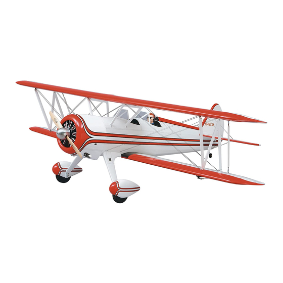
Wingspan: Top Wing: 71.5 in [1815mm]
Bottom Wing: 69 in [1755mm]
Wing Area: Top WIng: 762 sq in [49.1 dm
Bottom Wing: 704 sq in [45.4 dm
Weight: 14.5-15.5 lb [6580-7030 g]
Great Planes
®
Model Manufacturing Co. guarantees this kit to
be free from defects in both material and workmanship at the date
of purchase. This warranty does not cover any component parts
damaged by use or modification. In no case shall Great Planes'
liability exceed the original cost of the purchased kit. Further,
Great Planes reserves the right to change or modify this warranty
without notice.
In that Great Planes has no control over the final assembly or
material used for final assembly, no liability shall be assumed nor
accepted for any damage resulting from the use by the user of the
final user-assembled product. By the act of using the user-
assembled product, the user accepts all resulting liability.
READ THIS MANUAL BEFORE STARTING
CONSTRUCTION. IT CONTAINS IMPORTANT
INSTRUCTIONS AND WARNINGS CONCERNING
THE ASSEMBLY AND USE OF THIS MODEL.
Entire Contents © Copyright 2004
INSTRUCTION MANUAL
2
]
2
]
WARRANTY
If the buyer is not prepared to accept the liability associated
with the use of this product, the buyer is advised to return
this kit immediately in new and unused condition to the place
of purchase.
To make a warranty claim, send
the defective part or item to
Hobby Services at this address.
Include a letter stating your name, return shipping address, as
much contact information as possible (daytime telephone number,
fax number, e-mail address), a detailed description of the problem
and a photocopy of the purchase receipt. Upon receipt of the
package the problem will be evaluated as quickly as possible.
Wing Loading: 23-24 oz/sq ft [69-74 g/dm
Length: 57 in [1450mm]
Radio: 4-channel with 5-7 servos
Engine: .91-1.08 cu in [15-17.5cc] two-stroke,
1.20-1.40 cu in [19.5-23cc] four-stroke
3002 N. Apollo Dr. Suite 1
Champaign IL 61822
Champaign, Illinois
Telephone: (217) 398-8970 ext. 5
airsupport@greatplanes.com
2
]
Hobby Services
USA
GPMZ0295 for GPMA1350 V1
Advertisement
Table of Contents

Related Manuals for GREAT PLANES Super Stearman


Summary of Contents for GREAT PLANES Super Stearman
-
Page 1: Instruction Manual
Champaign IL 61822 Hobby Services at this address. In that Great Planes has no control over the final assembly or Include a letter stating your name, return shipping address, as material used for final assembly, no liability shall be assumed nor... -
Page 2: Table Of Contents
PREFLIGHT ....... . 36 1. Your Super Stearman should not be considered a toy, but Identify Your Model . -
Page 3: Additional Items Required
2' [600mm] large, silicone fuel tubing (GPMQ4133) fiberglass parts. Optional: If building the Super Stearman with four aileron servos, in addition to the items previously mentioned you NOTE: We, as the kit manufacturer, provide you with a top quality... -
Page 4: Optional Supplies And Tools
(HCAR0667) steps to get another view of the same parts. Pliers with wire cutter (HCAR0630) · Robart Super Stand II (ROBP1402) The Super Stearman is factory-covered with Top Flite Hobbico ® Duster ™ can of compressed air (HCAR5500) MonoKote film. -
Page 5: Kit Inspection
KIT INSPECTION Before starting to build, take an inventory of this kit to make Great Planes Product Support sure it is complete, and inspect the parts to make sure they 3002 N Apollo Drive, Suite 1 are of acceptable quality. If any parts are missing or are not... -
Page 6: Ordering Replacement Parts
Ordering Replacement Parts Important Information about Working with Fiberglass Replacement parts for the Great Planes Super Stearman ARF are available using the order numbers in the Replacement If you have never worked with fiberglass there are a few Parts List that follows. The fastest, most economical service basic things you should be aware of. -
Page 7: Build The Wing
BUILD THE WING Install the Ailerons Do the right wing first so your work matches the photos the first time through. You can do one wing at a time, or work on them together. 6. Apply six drops of thin CA to the top and bottom of each hinge. - Page 8 2. A string is taped inside the servo bay. Carefully remove the string from the servo bay and tape it to the outside of the wing to prevent it from dropping back into the 6. Locate three 1/8" [3mm] straight plywood wing joiners wing.
-
Page 9: Install The Aileron Servos & Pushrods
9. Hold the wing together with masking tape while the glue is curing. Excess epoxy can be cleaned away with denatured alcohol and a paper towel. 10. Glue the top wing together using the straight wing joiner and following the same gluing procedure used on the bottom wing. - Page 10 the clevis. Drill a 5/64" [2mm] hole in the outer hole of the charge receptacle to fit into. Drill a 1/16" [16mm] hole into the servo arm. Center the servo and the aileron. With a fine-tip fuselage through each of the mounting holes in the charge marker, mark the wire where it aligns with the outer hole of receptacle.
-
Page 11: Build The Fuselage
BUILD THE FUSELAGE Preparations 14. Place the wing bolt plate in position over the holes in the bottom wing. Use the nylon wing bolts to help you align the holes in the plate with the holes in the wing. Trace the outline of the plate onto the covering with a felt-tip pen. -
Page 12: Install The Stab, Elevator, Fin & Rudder
Install the Stab, Elevator, Fin & Rudder 4. Cut the covering on the top and bottom of the stab inside the line you have drawn. Use the same technique for removing the covering from the wing. 1. Temporarily attach the lower wing to the fuselage with the 1/4-20 nylon bolts. - Page 13 Did you know? ...The Stearman gained a reputation as a rugged airplane and a good teacher. Officially named the Boeing Model 75, the plane was (and still is) persistently known as the “Stearman” by many who flew them. It was called the “PT”...
-
Page 14: Attach The Wing & Cabanes
Pratt & Whitney 450 h.p. engines and utilized as crop dusters. These more powerful Stearmans are also commonly known as the “Super Stearman” and used for wing-walking or aerobatic routines at air shows. Attach the Wing and Cabanes 1. - Page 15 3. Look closely on the top of the bottom wing and you 5. Position the “N” strut to the bracket. Located on the will find a small pin hole locating the blind nuts for the strut is a piece of masking tape with an arrow that indicates cabane mounting bolts.
- Page 16 10. Install the four remaining brackets in the blind nuts at the ends of the wing. 11. Place the top wing onto the “N” struts. Attach the top wing to the “N” struts with 4-40 x 1/2" [13mm] phillips head screws, #4 washers and 4-40 nylon lock nuts the same way you installed the strut to the lower brackets.
-
Page 17: Install The Aileron Connection Rod
Install the Aileron Connecting Rod If you have decided to install four servos in the wings instead of two, skip the 12 steps in this section and proceed to, “Build the Carry Handle”. 3. On the top wing, on the bottom of the aileron is a large plywood plate. - Page 18 6. Locate the aileron connecting rod. Cut the excess rubber coating to expose all of the threads. 9. Attach the remaining control horn to the other end of the connecting rod. Adjust the clevises so that the length of the connecting rod allows the top aileron and bottom ailerons to be neutral.
-
Page 19: Build The Carry Handle
Build the Carry Handle This kit comes with a convenient carrying handle for the fuselage and the struts. It is also useful during the remainder of the construction process because, when installed, it will allow you to turn the plane upside-down on the workbench without flexing or bending the center cabanes. -
Page 20: Install The Engine & Throttle Servo
8-32 tap. Did you know? ...The primary differences between the “Super Stearman” and the original wartime Stearmans are the larger 450 horsepower Pratt and Whitney engine, additional flying and landing wires, the installation of two additional ailerons on the top wing, cowl and wheel pants! 3. - Page 21 4. Drill a 3/16" [4.8mm] hole through the firewall in line with the throttle arm on the carburetor. 5. Locate the 24" [610mm] gray plastic pushrod tube and cut it 12-3/4" [324mm] in length. Sand one end of the tube with 220-grit sandpaper.
-
Page 22: Install The Cowl & Dummy Engine
Install the Cowl & Dummy Engine 3. Position the cowl ring and the tabs on the reference marks on the front of the firewall. When properly positioned the top of the cowl ring should be flush with the top of the fuselage and the 1. - Page 23 centering it as much as possible. At the point where the engine begins to make contact with the cowl, mark the inside of the cowl with a felt-tip marker. Make small cut outs in the cowl where the engine contacts the fuselage until you can completely slide the cowl into position.
-
Page 24: Install The Fuel Tank
Install the Fuel Tank 13. Paint the engine flat black. After the paint dries install the aluminum tubes and wire into the holes you drilled. On the back of the engine apply a small amount of glue to each 1. Assemble the fuel tank as shown in the sketch. When wire and aluminum tube to hold them in place. -
Page 25: Assemble The Nose Weight Box
Assemble Nose Weight Box Our prototype model required the addition of nose weight. This is not uncommon for short-coupled airplanes such as the Stearman. We have included a location for you to easily add the weight that most likely will be needed. 2. -
Page 26: Install The Wheels & Wheel Pants
Install the Wheels & Wheel Pants 1. Install the tail wheel onto the tail wheel wire, securing it with a 3/32" [2.4mm] wheel collar and a 4-40 set screw. 5. Glue the blocks to the engine mount rails with CA. Drill two 3/32"... - Page 27 1/4 ounce [2cc] of 6-minute epoxy and a small amount of microballoon filler. Locate one of the plywood wheel pant plates and glue it inside the pant, aligning the hole in the plate with the hole you made in the side of the pant. Clamp the plate to the pant and allow the glue to fully cure.
-
Page 28: Install The Radio System
Install the Radio System 1. Cut the covering from the pushrod tube openings at the rear of the fuselage. There are two located on the right side and one located on the left. If you have trouble finding the openings, slide a .074" x 36" [1.9 x 915mm] pushrod wire into the tubes from inside of the fuselage, sliding it into the tube until it pushes the covering away from the fuselage slightly. - Page 29 8. Bend the outer elevator pushrod as shown. Cut off the 10. Locate the 1/8" [3mm] plywood receiver/battery tray. excess wire. Center both of the elevators, then center the Place it on top of the hardwood sticks you glued in and place elevator servo.
-
Page 30: Finishing Touches
Finishing Touches 1. Paint the cockpits flat black. 12. We installed the radio switch and the battery charge jack inside the front cockpit. Place a pilot in the cockpit as your guide for positioning the switch and charge jack. 2. Locate two pieces of black cockpit coaming. Look closely and you will see that there is a slit in it. - Page 31 1/4" [6mm] and make a crossing mark. Do the bolt as needed to fit your particular application. Spinner nuts same on the leading edge of the stab. Do this on both sides for other engines are available from Great Planes, CB of the stab. Associates and True Turn.
- Page 32 4. Cut a piece of the elastic cord 50" [1270mm] long. This length should be relaxed, not stretched. In order to feed the elastic cord through the holes you have drilled, apply a few drops of thin CA to one end of the elastic cord, covering approximately 1"...
- Page 33 9. Put a small drop of CA on the cord, then insert it into the hole shown. 12. Cut two elastic cords 25" [635mm] long. Use CA to glue the ends together forming a loop. When gluing the ends together, overlap the cord approximately 1/2" [13mm]. 10.
-
Page 34: Apply The Decals
Apply the Decals The Stearman was primarily a fabric-covered aircraft, but there were some panel lines along the top of the fuselage. In addition to the photographs on the box the following pictures should help you in the placement of the decals. 14. -
Page 35: Get The Model Ready To Fly
2. With the transmitter and receiver still on, check all the control surfaces to see if they are centered. If necessary, adjust Use a Great Planes AccuThrow (or a ruler) to accurately the clevises on the pushrods to center the control surfaces. -
Page 36: Balance The Model (C.g.)
2. With the wing attached to the fuselage, all parts of the Balance the Model (C.G.) model installed (ready to fly) and an empty fuel tank, lift it at the balance point you marked. More than any other factor, the C.G. (balance point) can 3. -
Page 37: Balance Propellers
We use a Top Flite Precision Magnetic Prop Balancer ™ (TOPQ5700) in the workshop and keep a Great Planes Keep these items away from the prop: loose clothing, shirt Fingertip Prop Balancer (GPMQ5000) in our flight box. -
Page 38: Ama Safety Code
AMA SAFETY CODE ( excerpts ) IMAA SAFETY CODE ( excerpts ) Read and abide by the following Academy of Model Since the Stearman qualifies as a “giant scale” model Aeronautics Official Safety Code: and is therefore eligible to fly in IMAA events, we’ve included excerpts from the IMAA Safety Code. -
Page 39: Check List
CHECK LIST FLYING During the last few moments of preparation your mind may be elsewhere anticipating the excitement of the first flight. Because of this, you may be more likely to overlook certain Fuel Mixture Adjustments checks and procedures that should be performed before the model is flown. -
Page 40: Takeoff
GOOD LUCK AND GREAT FLYING! take off, most models fly more smoothly at reduced speeds. Take it easy with the Super Stearman for the first few flights, gradually getting acquainted with it as you gain confidence. Adjust the trims to maintain straight and level flight. After...
Need help?
Do you have a question about the Super Stearman and is the answer not in the manual?
Questions and answers