Pro-Form Le Tour de France User Manual
Hide thumbs
Also See for Le Tour de France:
- User manual (32 pages) ,
- User manual (28 pages) ,
- User manual (28 pages)
Advertisement
Table of Contents
- 1 Table of Contents
- 2 Warning Decal Placement
- 3 Important Precautions
- 4 Before You Begin
- 5 Part Identification Chart
- 6 Assembly
- 7 Have a Second Person Hold the Console (9) Near
- 8 How to Use the Training Bike
- 9 Maintenance and Troubleshooting
- 10 Exercise Guidelines
- 11 Part List
- 12 Exploded Drawing
- 13 Ordering Replacement Parts
- 14 Recycling Information
- Download this manual
Model No. PFEVEX71413.1
Serial No.
Write the serial number in the space
above for reference.
USER'S MANUAL
Serial Number
Decal (under frame)
CUSTOMER SERVICE
UNITED KINGDOM
Call: 08457 089 009
From Ireland: 053 92 36102
Website: www.iconsupport.eu
E-mail: csuk@iconeurope.com
Write:
ICON Health & Fitness, Ltd.
c/o HI Group PLC
Express Way
CASTLEFORD
WF10 5QJ
UNITED KINGDOM
AUSTRALIA
Call: 1800 993 770
E-mail: australiacc@iconfitness.com
Write:
ICON Health & Fitness
PO Box 635
WINSTON HILLS NSW 2153
AUSTRALIA
CAUTION
Read all precautions and instruc-
tions in this manual before using
this equipment. Keep this manual
for future reference.
www.iconeurope.com
Advertisement
Table of Contents

Related Manuals for Pro-Form Le Tour de France


Summary of Contents for Pro-Form Le Tour de France
- Page 1 Model No. PFEVEX71413.1 Serial No. Write the serial number in the space above for reference. USER’S MANUAL Serial Number Decal (under frame) CUSTOMER SERVICE UNITED KINGDOM Call: 08457 089 009 From Ireland: 053 92 36102 Website: www.iconsupport.eu E-mail: csuk@iconeurope.com Write: ICON Health &...
-
Page 2: Table Of Contents
PROFORM is a registered trademark of ICON IP, Inc. LE TOUR DE FRANCE is a registered trademark of Societe du Tour de France. iPad is a trademark of Apple Computer, Inc., registered in the U.S. and other countries. iPad ®... -
Page 3: Important Precautions
IMPORTANT PRECAUTIONS WARNING: To reduce the risk of burns, fire, electric shock, or injury to persons, read all important precautions and instructions in this manual and all warnings on your training bike before using your training bike. ICON assumes no responsibility for personal injury or property damage sustained by or through the use of this product. -
Page 4: Before You Begin
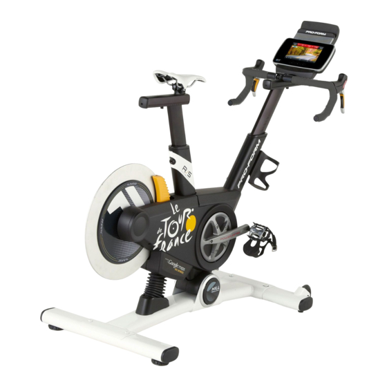
To help us assist you, note the product model ® ® The LE TOUR DE FRANCE training bike is unlike any number and serial number before contacting us. The ordinary exercise bike. With full adjustability, a Wi-Fi model number and the location of the serial number cycling console, an incline system that simulates actual decal are shown on the front cover of this manual. -
Page 5: Part Identification Chart
PART IDENTIFICATION CHART Use the drawings below to identify the small parts needed for assembly. The number in parentheses below each drawing is the key number of the part, from the PART LIST near the end of this manual. The number following the key number is the quantity needed for assembly. -
Page 6: Assembly
ASSEMBLY • Assembly requires two persons. • To identify small parts, see page 5. • Place all parts in a cleared area and remove the • In addition to the included tool(s), assembly packing materials. Do not dispose of the packing requires the following tools: materials until you fi... - Page 7 3. If there are shipping screws in the Rear Stabilizer (23), remove and discard them. Attach the Rear Stabilizer (23) to the Base (1) with two M10 x 58mm Screws (74). 4. See the inset drawing. Using a plastic bag Grease to keep your fingers clean, apply some of the included grease to the sides of the channel on...
- Page 8 5. Tip: You can attach your own saddle to the Saddle Carriage (4) if desired. Loosen the attachment hardware (not shown) beneath the Saddle (5), and remove the Saddle. Then, attach your own saddle and retighten the attachment hardware. Orient the Saddle Carriage (4) as shown. Loosen the indicated M8 x 15mm Round Head Screw (115), and slide the Saddle Carriage (4) into the Saddle Post (3).
-
Page 9: Have A Second Person Hold The Console (9) Near
7. Have a second person hold the Handlebar (7) near the Handlebar Carriage (105). Locate one of the remaining wire ties in the Handlebar Carriage (105). Tie the indicated end of the wire tie to the Right Extension Wire (107). Then, pull the other end of the wire tie until the Right Extension Wire is routed through the Handlebar Carriage. - Page 10 10. Tip: Avoid pinching the wires. Attach the Console (9) to the Handlebar Carriage (105) with four M4 x 12mm Screws (111). Avoid pinching the wires 11. Attach the Tray (8) to the Frame (2) with two M4 x 10mm Screws (116). 12.
-
Page 11: How To Use The Training Bike
HOW TO USE THE TRAINING BIKE HOW TO PLUG IN THE POWER CORD Follow the steps below to plug in the power cord. This product must be earthed. If it should malfunc- 1. Plug the indicated end of the power cord into the tion or break down, earthing provides a path of least socket on the frame. - Page 12 FEATURES OF THE TRAINING BIKE HOW TO ADJUST THE GEOMETRY OF THE TRAINING BIKE Watts Measurement The training bike can be adjusted to match the geom- Each training bike is individually calibrated to measure etry of your road bike to promote correct form and to your power output and allow you to monitor your watts ensure proper training of the muscles.
- Page 13 How to Adjust the Saddle Post HOW TO LEVEL THE TRAINING BIKE For effective train- If the training bike ing, the saddle rocks slightly on should be at the your floor during proper height. As use, turn one or you pedal, there both of the level- Saddle should be a slight...
- Page 14 CONSOLE DIAGRAM MAKE YOUR TRAINING GOALS A REALITY WITH Upload your workout results to the iFit cloud IFIT.COM and track your accomplishments. With your new iFit-compatible training bike, you can use an array of features on iFit.com to make your train- Set calorie, time, distance, or watts goals ing goals a reality: for your workouts.
- Page 15 (resistance) of the training bike to match the incline system is calibrated. real terrain of the Le Tour de France bicycle race and allows you to change gears to maintain your desired IMPORTANT: If the incline system does not cali- pedaling cadence.
- Page 16 To use the manual mode, see page 17. To use a 22). Press the back button to return to the previ- Le Tour de France workout, see page 19. To use ous screen. a set-a-goal workout, see page 20. To use an iFit workout, see page 21.
- Page 17 HOW TO USE THE MANUAL MODE Change gears by pressing the buttons on the shifters. Note: After you press a button, it will take 1. Touch the screen or begin pedaling to activate a moment for the training bike to change to the the console.
- Page 18 6. Do intervals if desired. 7. Wear a heart rate monitor and measure your heart rate if desired. During a workout, you can use the interval screen to measure your performance for short periods of You can wear an optional heart rate monitor to time.
- Page 19 3. Select a Le Tour de France workout. out, touch the Follow Workout button. To select a Le Tour de France workout, first touch Note: The calorie goal is an estimate of the the cyclist button at the bottom of the screen. The number of calories that you will burn during the workouts menu will appear on the screen.
- Page 20 HOW TO USE A SET-A-GOAL WORKOUT The workout will continue until you reach the goal that you set. A workout summary will appear on 1. Touch the screen or begin pedaling to activate the screen. After you view the workout summary, the console.
- Page 21 HOW TO USE AN IFIT WORKOUT When you select an iFit workout, the screen will show the name, the estimated duration, and the Note: To use an iFit workout, you must have access distance of the workout. The screen will also show to a wireless network (see HOW TO USE THE the approximate number of calories you will burn WIRELESS NETWORK MODE on page 25).
- Page 22 HOW TO USE THE EQUIPMENT SETTINGS MODE 6. Select a time for the cadence timeout. 1. Select the settings main menu. The console features a cadence timeout feature; if no buttons are touched or pressed and the pedals Turn on the console and select the main menu do not move for a set amount of time, the console (see steps 1 and 2 on page 17).
- Page 23 9. Hide or display the gears button. 12. Enable or disable street view. The console features an option to hide the gears During some workouts, the screen may show a button to prevent unauthorized users from access- map. To enable or disable the street view feature of ing the settings main menu.
- Page 24 HOW TO USE THE MAINTENANCE MODE The training bike will automatically rise to the maxi- mum incline level, lower to the minimum incline 1. Select the settings main menu. level, and then return to the starting position. This will calibrate the incline system. See step 1 on page 22.
- Page 25 HOW TO USE THE WIRELESS NETWORK MODE When a list of networks appears, touch the desired network. Note: You will need to know your network The console features a wireless network mode that name (SSID). If your network has a password, you allows you to set up a wireless network connection.
- Page 26 HOW TO USE THE SOUND SYSTEM To use the keyboard, see HOW TO USE THE TOUCH SCREEN on page 16. To play music or audio books through the console sound system while you exercise, plug a 3.5 mm male To enter a different web address in the URL bar, first, to 3.5 mm male audio cable (not included) into the jack slide your finger down the screen to view the URL bar, on the console and into a jack on your MP3 player,...
-
Page 27: Maintenance And Troubleshooting
MAINTENANCE AND TROUBLESHOOTING HOW TO MAINTAIN THE TRAINING BIKE HOW TO ADJUST THE DRIVE BELT Inspect and tighten all parts of the training bike regu- If the pedals slip while you are pedaling, the drive belt larly. Replace any worn parts immediately. may need to be adjusted. -
Page 28: Exercise Guidelines
EXERCISE GUIDELINES Aerobic Exercise—If your goal is to strengthen your WARNING: cardiovascular system, you must perform aerobic Before beginning this exercise, which is activity that requires large amounts or any exercise program, consult your physi- of oxygen for prolonged periods of time. For aerobic cian. -
Page 29: Part List
PART LIST Model No. PFEVEX71413.1 R0114A Key No. Qty. Description Key No. Qty. Description Base Board Bracket Frame Standoff Saddle Post Crank/Torque Pulley Saddle Carriage M4 Washer Saddle Magnet Handlebar Post Crank Screw Handlebar Bearing Tray Push Nut Console Frame Bushing Upper Shield Pivot Axle Left Shield... - Page 30 Key No. Qty. Description Key No. Qty. Description Reed Switch/Wire M8 x 15mm Round Head Screw Crank Hub M4 x 10mm Screw Crank Spacer M4 x 14mm Screw M8 Locknut M8 x 30mm Screw Handlebar Carriage Back Plate M8 x 20mm Screw Pulley Spacer Right Extension Wire –...
-
Page 31: Exploded Drawing
EXPLODED DRAWING Model No. PFEVEX71413.1 R0114A... -
Page 32: Ordering Replacement Parts
ORDERING REPLACEMENT PARTS To order replacement parts, please see the front cover of this manual. To help us assist you, be prepared to provide the following information when contacting us: • the model number and serial number of the product (see the front cover of this manual) •...
Need help?
Do you have a question about the Le Tour de France and is the answer not in the manual?
Questions and answers
After an extended period of non-use when I power the unit up I don't see movement of the resistance magnets - so, there isn't any change in resistance when changing gears or change in incline
If the resistance magnets on a Pro-Form Le Tour de France do not move or change resistance after a long period of non-use, calibrate the incline system by entering the maintenance mode. The bike will automatically rise to the maximum incline, lower to the minimum, and return to the starting position. Ensure that pets, feet, and objects are kept away during calibration.
This answer is automatically generated