Table of Contents
Advertisement
Quick Links
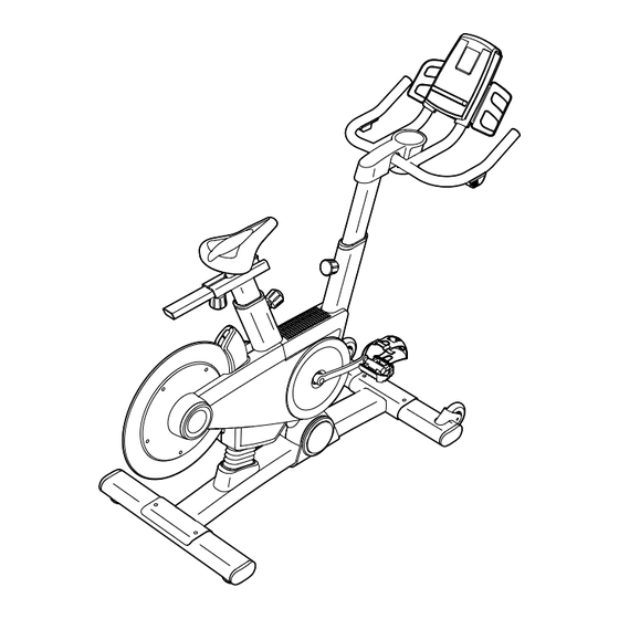
Model No. PFEVEX79911.0
Serial No.
Write the serial number in the space
above for reference.
USER’'S MANUAL
Serial Number
Decal
QUESTIONS?
If you have questions, or if there are
missing parts, please contact us:
UNITED KINGDOM
Call: 08457 089 009
From Ireland: 053 92 36102
Website: www.iconsupport.eu
E-mail: csuk@iconeurope.com
Write:
ICON Health & Fitness, Ltd.
c/o HI Group PLC
Express Way
CASTLEFORD
WF10 5QJ
UNITED KINGDOM
AUSTRALIA
Call: 1800 993 770
E-mail: australiacc@iconfitness.com
Write:
ICON Health & Fitness
PO Box 635
WINSTON HILLS NSW 2153
AUSTRALIA
CAUTION
Read all precautions and instruc-
tions in this manual before using
this equipment. Keep this manual
for future reference.
www.iconeurope.com
Advertisement
Table of Contents

Related Manuals for Pro-Form PFEVEX79911.0


Summary of Contents for Pro-Form PFEVEX79911.0
- Page 1 Model No. PFEVEX79911.0 Serial No. Write the serial number in the space above for reference. USER’’S MANUAL Serial Number Decal QUESTIONS? If you have questions, or if there are missing parts, please contact us: UNITED KINGDOM Call: 08457 089 009 From Ireland: 053 92 36102 Website: www.iconsupport.eu...
-
Page 2: Table Of Contents
TABLE OF CONTENTS WARNING DECAL PLACEMENT ............. . . 2 IMPORTANT PRECAUTIONS . -
Page 3: Important Precautions
IMPORTANT PRECAUTIONS WARNING: To reduce the risk of serious injury, read all important precautions and instructions in this manual and all warnings on your exercise bike before using your exercise bike. ICON assumes no responsibility for personal injury or property damage sustained by or through the use of this product. -
Page 4: Before You Begin
BEFORE YOU BEGIN Congratulations for selecting the revolutionary reading this manual, please see the front cover of this PROFORM LE TOUR DE FRANCE exercise bike. manual. To help us assist you, note the product model ® ® The LE TOUR DE FRANCE exercise bike is unlike any number and serial number before contacting us. -
Page 5: Part Identification Chart
PART IDENTIFICATION CHART Use the drawings below to identify the small parts needed for assembly. The number in parentheses below each drawing is the key number of the part, from the PART LIST near the end of this manual. The number following the key number is the quantity needed for assembly. -
Page 6: Assembly
ASSEMBLY •• Assembly requires two persons. •• In addition to the included tool(s), assembly requires the following tools: •• Place all parts in a cleared area and remove the one Phillips screwdriver packing materials. Do not dispose of the packing materials until you complete all assembly steps. - Page 7 2. While a second person lifts the rear of the Base (1), attach the Rear Stabilizer (23) to the Base with two 3/8" x 2 1/4" Screws (74). 3. Orient the Seat Post (3) as shown. Loosen the indicated Post Knob (47) and pull it outward.
- Page 8 4. Orient the Seat Carriage (4) as shown. Loosen the Seat Knob (29) and pull it downward. Then, slide the Seat Carriage (4) into the Seat Post (3). Slide the Seat Carriage (4) to the desired posi- tion, release the Seat Knob (29) into one of the Holes adjustment holes in the Seat Carriage, and then tighten the Seat Knob.
- Page 9 6. Orient the Handlebar Post (6) as shown. Have a second person hold the Handlebar Post Avoid pinching the Lower Wire (69) (6) near the Frame (2). Locate the wire tie in the Handlebar Post, and tie the lower end of the wire tie to the Lower Wire (69).
- Page 10 8. Orient the Handlebar Cover (67) as shown and hold it near the Handlebar (7). Connect the receiver wire (B) to the Extension Wire (102). Carefully insert the excess wire into the Handlebar (7). Tip: Avoid pinching the wires. Insert a #8 x 5/8"...
- Page 11 10. Plug the Left and Right Shifter Wires (70, 81) in the Handlebar (7) into the receptacles marked ““R”” and ““L”” on the back of the Console (9). Next, plug the Extension Wire (102) into the receptacle marked ““Pulse.”” Plug the Upper Wire (68) into the remaining receptacle.
- Page 12 12. Identify the Left Pedal (61), which is marked with an ““L.”” Using an adjustable wrench, firmly tighten the Left Pedal (61) counterclockwise into the Left Crank Arm (63). Tighten the Right Pedal (not shown) clockwise into the Right Crank Arm (not shown). 13.
-
Page 13: How To Use The Exercise Bike
HOW TO USE THE EXERCISE BIKE HOW TO PLUG IN THE POWER CORD Follow the steps below to plug in the power cord. This product must be earthed. If it should malfunction 1. Plug the power cord into the receptacle on the or break down, earthing provides a path of least resis- exercise bike. - Page 14 HOW TO ADJUST THE ANGLE OF THE SEAT HOW TO ADJUST THE HANDLEBAR POST You can adjust the angle of the seat to the position that To adjust the height is most comfortable. You can also slide the seat for- of the handlebar ward or backward to increase your comfort or to adjust post, first loosen the...
- Page 15 CONSOLE DIAGRAM FEATURES OF THE CONSOLE While you exercise, the console will display continuous exercise feedback. You can also measure your heart The advanced console offers an array of features rate using an optional heart rate monitor. designed to make your workouts more effective and enjoyable.
- Page 16 HOW TO TURN ON THE POWER HOW TO NAVIGATE THE CONSOLE MENUS IMPORTANT: If the exercise bike has been exposed You can use the Home, left, right, up, down, and Enter to cold temperatures, allow it to warm to room buttons on the console to navigate through menus in temperature before turning on the power.
- Page 17 HOW TO SET UP THE CONSOLE HOW TO USE THE MANUAL MODE Before using the exercise bike for the first time, set up 1. Begin pedaling or press any button on the the console. console to turn on the console. 1.
- Page 18 6. Follow your progress with the display. The wireless symbol at the top of the display will show The display can show the following workout the connection status of the information. Press the Display button or the left, console. If the symbol is green, right, up, and down buttons to view the desired the console is connected to workout information.
- Page 19 HOW TO USE AN ONBOARD WORKOUT The display will also show a map of the trail and a marker indicating your progress. Press the Display 1. Begin pedaling or press any button on the button repeatedly to view the map. console to turn on the console.
- Page 20 HOW TO USE THE WATTS WORKOUT The target watts meter will show your watts output relative to the target watts setting. When the arrow 1. Begin pedaling or press any button on the is in the green zone, your watts output is close to console to turn on the console.
- Page 21 HOW TO USE AN IFIT LIVE WORKOUT Before some workouts will download, you must add them to your schedule on iFit.com. Note: To use an iFit Live workout, you must have access to a wireless network including an 802.11b/n For more information about the iFit Live work- router with SSID broadcast enabled (hidden networks outs, please see www.iFit.com.
- Page 22 HOW TO USE THE SETTINGS MODE If you are having problems connecting to the selected network, make sure that your password is The console features a settings mode that allows you correct. Note: Passwords are case-sensitive. to connect the console to your own wireless network and to log in to your iFit Live account.
- Page 23 3. Log in to your iFit Live account. You can turn on or turn off the display demo mode. From the settings menu, select Demo Mode. The From the settings menu, select WiFi. Then, select currently selected demo mode option will be iFit Live Login.
- Page 24 HOW TO USE THE MAINTENANCE MODE 4. Restore the default settings. The console features a maintenance mode that allows From the maintenance menu, select Restore you to update the console firmware, restore the default Defaults. Then, press Enter to restore the console settings, view technical information, perform a net- to the original settings from the factory.
- Page 25 8. Calibrate the power meter on the exercise bike. Next, press the play button on your MP3 player or CD player. Adjust Note: This feature may not be enabled for this the volume level using the volume exercise bike. increase and decrease buttons on the console or the volume control Calibrate the power meter on the exercise bike on your MP3 player or CD player.
-
Page 26: Maintenance And Troubleshooting
MAINTENANCE AND TROUBLESHOOTING HOW TO MAINTAIN THE EXERCISE BIKE Locate the Reed Switch (35). Loosen, but do not remove, the two #8 x 19mm Tek Screws (97). Inspect and tighten all parts of the exercise bike regu- larly. Replace any worn parts immediately. To clean the exercise bike, use a damp cloth and a small amount of mild detergent. - Page 27 HOW TO ADJUST THE DRIVE BELT Locate the access hole in the underside of the Right Shield (12). Using a hex key, tighten the Idler If the pedals slip while you are pedaling, the drive belt Adjustment Screw (39) until the Drive Belt (66) is tight. may need to be adjusted.
-
Page 28: Exercise Guidelines
EXERCISE GUIDELINES Aerobic Exercise——If your goal is to strengthen your WARNING: cardiovascular system, you must perform aerobic Before beginning this exercise, which is activity that requires large amounts or any exercise program, consult your physi- of oxygen for prolonged periods of time. For aerobic cian. -
Page 29: Part List
PART LIST Model No. PFEVEX79911.0 R0312A Key No. Qty. Description Key No. Qty. Description Base Post Bushing Frame Post Knob Seat Post Power Switch Seat Carriage Grommet Seat Control Board Handlebar Post Board Bracket Handlebar Standoff Tray Crank Pulley Console... - Page 30 Key No. Qty. Description Key No. Qty. Description 5/16”” x 3/4”” Screw 1/4" Split Washer #8 x 1/4" Screw M3.5 x 13mm Screw #8 Star Washer 5/16" x 2 1/4" Screw #8 x 5/8" Screw Wire Guide #8 x 1/2" Screw ––...
-
Page 31: Exploded Drawing
EXPLODED DRAWING Model No. PFEVEX79911.0 R0312A 48 49... -
Page 32: Ordering Replacement Parts
ORDERING REPLACEMENT PARTS To order replacement parts, please see the front cover of this manual. To help us assist you, be prepared to provide the following information when contacting us: •• the model number and serial number of the product (see the front cover of this manual) ••...
Need help?
Do you have a question about the PFEVEX79911.0 and is the answer not in the manual?
Questions and answers