Table of Contents
Advertisement
proform.com
Model No. PFEX73920.0
Serial No.
Write the serial number in the space
above for reference.
Serial
Number
Decal
ACTIVATE YOUR
WARRANTY
To register your product and
activate your warranty today,
go to my.proform.com.
CUSTOMER CARE
For service at any time, go to
support.proform.com.
Or call 1-866-362-4490
Mon.–Fri. 6 a.m.–6 p.m. MT
Sat. 8 a.m.–12 p.m. MT
Please do not contact the store.
CAUTION
Read all precautions and
instructions in this manual before
using this equipment. Keep this
manual for future reference.
USER'S MANUAL
Advertisement
Table of Contents

Related Manuals for Pro-Form LE TOUR DE FRANCE CLC


Summary of Contents for Pro-Form LE TOUR DE FRANCE CLC
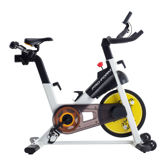
- Page 1 proform.com Model No. PFEX73920.0 Serial No. USER’S MANUAL Write the serial number in the space above for reference. Serial Number Decal ACTIVATE YOUR WARRANTY To register your product and activate your warranty today, go to my.proform.com. CUSTOMER CARE For service at any time, go to support.proform.com.
-
Page 2: Table Of Contents
TABLE OF CONTENTS WARNING DECAL PLACEMENT ............. . .2 IMPORTANT PRECAUTIONS . -
Page 3: Important Precautions
IMPORTANT PRECAUTIONS WARNING: To reduce the risk of serious injury, read all important precautions and instructions in this manual and all warnings on your exercise bike before using your exercise bike. ICON assumes no responsibility for personal injury or property damage sustained by or through the use of this product. - Page 4 STANDARD SERVICE PLANS...
-
Page 5: Before You Begin
The model number and the location of the serial number LE TOUR DE FRANCE CLC exercise bike provides a decal are shown on the front cover of this manual. selection of features designed to make your workouts at home more effective and enjoyable. -
Page 6: Part Identification Chart
M4 x 25mm M6 x 15mm M10 x 25mm Screw (6)–1 Screw (71)–4 Screw (69)–4 PART IDENTIFICATION CHART Use the drawings below to identify the small parts needed for assembly. The number in parentheses below each drawing is the key number of the part, from the PART LIST near the end of this manual. The number following the key number is the quantity needed for assembly. -
Page 7: Assembly
ASSEMBLY • To hire an authorized service technician to • In addition to the included tool(s), assembly assemble this product, call 1-800-445-2480. requires the following tool(s): one Phillips screwdriver • Assembly requires two persons. one adjustable wrench • Place all parts in a cleared area and remove the packing materials. - Page 8 2. If there are shipping tubes (not shown) attached to the front and rear of the Frame (1), remove and discard the shipping tubes and the hardware attaching them. Orient the Front Stabilizer (2) as shown, and attach it to the Frame (1) with two M10 x 25mm Screws (69).
- Page 9 4. Tip: See the inset drawing to learn how to operate the Adjustment Handle (14). Loosen handle Locate the Adjustment Handle (14) on the rear of the Frame (1). Pull the Adjustment Handle Pull handle outward, and insert the Saddle Post (7) into the Frame.
- Page 10 6. Note: You can attach your own pedals if desired. Identify the Right Pedal (16). Using the included wrench, firmly tighten the Right Pedal clockwise into the Right Crank Arm (18). Firmly tighten the Left Pedal (17) counterclockwise into the Left Crank Arm (not shown).
- Page 11 8. See the inset drawing. Connect the connector on the Upper Wire (56) to the connector on the Lower Wire (82). Next, tighten the zip tie (C) around the indicated mark (D) on the Upper Wire (56). Then, cut off the excess zip tie.
- Page 12 10. The Console (5) requires three AA batteries (not included); alkaline batteries are recommended. Do not use old and new batteries together or alkaline, standard, and rechargeable batter- ies together. IMPORTANT: If the Console has been exposed to cold temperatures, allow it to warm to room temperature before you insert batteries.
- Page 13 13. Connect the Console Wire (G) to the Upper Wire (56); make sure to align the connectors properly and make sure to press the connectors together firmly. Next, press the Wire Protector (85) around the Console Wire (G) in the location shown. Then, insert the Wires (G, 56) into the Handlebar (4), and press the Wire Protector (85) into the Handlebar.
-
Page 14: How To Use The Exercise Bike
HOW TO USE THE EXERCISE BIKE HOW TO LEVEL THE EXERCISE BIKE HOW TO ADJUST THE HORIZONTAL POSITION OF THE SADDLE If the exercise bike rocks slightly on your To adjust the position floor during use, of the saddle, first turn one or both of loosen the carriage the leveling feet (A) - Page 15 HOW TO ADJUST THE SADDLE POST HOW TO ADJUST THE HANDLEBAR For effective exercise, the saddle should be at the To adjust the height of the proper height. As you pedal, there should be a slight handlebar, first bend in your knees when the pedals are in the lowest position.
- Page 16 HOW TO USE THE PEDALS HOW TO USE THE BRAKE KNOB To use the pedals (F), To change the resis- insert your shoes into tance of the pedals, the toe cages and press the buttons on pull the ends of the the console (see step toe straps.
-
Page 17: How To Use The Console
HOW TO USE THE CONSOLE CONSOLE DIAGRAM FEATURES OF THE CONSOLE You can also connect your tablet to the console and use the iFit –Smart Cardio Equipment app to record ® The easy-to-use console enables you to change the and track your workout information. resistance of the pedals with the touch of a button To use the manual mode, see page 18. - Page 18 HOW TO USE THE MANUAL MODE RPM (circular arrow icon)—This mode displays your pedaling speed, in revolutions per minute 1. Begin pedaling or press any button on the (RPM). console to turn on the console. Time (clock icon)—This mode displays the When you turn on the console, the display will turn elapsed time that you have pedaled during your on.
- Page 19 4. Wear a heart rate monitor and measure your 5. When you are finished exercising, the console heart rate if desired. will turn off automatically. You can wear an optional heart rate monitor The console has an auto-off feature. If the pedals to measure your heart rate.
- Page 20 HOW TO CONNECT YOUR TABLET TO THE 4. Record and track your workout information. CONSOLE Follow the instructions in the iFit–Smart Cardio The console supports Bluetooth connections to tab- Equipment app to record and track your workout lets via the iFit–Smart Cardio Equipment app and to information.
-
Page 21: Fcc Information
THE OPTIONAL CHEST HEART RATE MONITOR proper heart rate during your workouts. The optional chest heart rate monitor will enable you to continuously Whether your monitor your heart rate while you exercise, helping you to reach your personal fitness goals. To purchase a goal is to chest heart rate monitor, please see the front cover burn fat or to... -
Page 22: Maintenance And Troubleshooting
MAINTENANCE AND TROUBLESHOOTING HOW TO MAINTAIN THE EXERCISE BIKE HOW TO ADJUST THE REED SWITCH Regular maintenance is important for optimal If the console does not display correct feedback, the performance and to reduce wear. Inspect and properly reed switch should be adjusted. tighten all parts each time the exercise bike is used. - Page 23 HOW TO ADJUST THE DRIVE BELT Then, tighten the M10 x 60mm Screw (65) until the Drive Belt (not shown) is tight. If you feel the pedals slip while you are pedaling, even when the resistance is adjusted to the highest level, When the Drive Belt (not shown) is tight, reattach the the drive belt may need to be adjusted.
-
Page 24: Exercise Guidelines
EXERCISE GUIDELINES Aerobic Exercise—If your goal is to strengthen your WARNING: cardiovascular system, you must perform aerobic Before beginning this exercise, which is activity that requires large amounts or any exercise program, consult your physi- of oxygen for prolonged periods of time. For aerobic cian. -
Page 25: Part List
PART LIST Model No. PFEX73920.0 R0919A Key No. Qty. Description Key No. Qty. Description Frame Pulley Front Stabilizer Drive Belt Rear Stabilizer Flywheel Handlebar Flywheel Axle Console/Mount Flywheel Bearing M4 x 25mm Screw Flywheel Spacer Saddle Post Wheel Saddle Foot Saddle Arm Leveling Foot Saddle Carriage... -
Page 26: Exploded Drawing
EXPLODED DRAWING A Model No. PFEX73920.0 R0919A... - Page 27 EXPLODED DRAWING B Model No. PFEX73920.0 R0919A...
-
Page 28: Ordering Replacement Parts
ORDERING REPLACEMENT PARTS To order replacement parts, please see the front cover of this manual. To help us assist you, be prepared to provide the following information when contacting us: • the model number and serial number of the product (see the front cover of this manual) •...
Need help?
Do you have a question about the LE TOUR DE FRANCE CLC and is the answer not in the manual?
Questions and answers