Advertisement
Table of Contents
- 1 Table of Contents
- 2 Warning Decal Placement
- 3 Important Precautions
- 4 Before You Begin
- 5 Part Identification Chart
- 6 Assembly
- 7 How to Use the Exercise Bike
- 8 Fcc Information
- 9 Maintenance and Troubleshooting
- 10 Exercise Guidelines
- 11 Part List
- 12 Exploded Drawing
- 13 Ordering Replacement Parts
- 14 Limited Warranty
- Download this manual
www.proform.com
Model No. PFEX51915.0
Serial No.
USER'S MANUAL
Write the serial number in the
space above for reference.
Serial Number
Decal
ACTIVATE YOUR
WARRANTY
To register your product and
activate your warranty today,
go to www.proformservice.com/
registration.
CUSTOMER CARE
For service at any time, go to
www.proformservice.com.
Or call 1-888-533-1333
Mon.–Fri. 6 a.m.–6 p.m. MT
Sat. 8 a.m.–12 p.m. MT
Please do not contact the store.
CAUTION
Read all precautions and instruc-
tions in this manual before using
this equipment. Keep this manual
for future reference.
Advertisement
Table of Contents

Subscribe to Our Youtube Channel
Related Manuals for Pro-Form 135 CSX


Summary of Contents for Pro-Form 135 CSX
- Page 1 www.proform.com Model No. PFEX51915.0 Serial No. USER’S MANUAL Write the serial number in the space above for reference. Serial Number Decal ACTIVATE YOUR WARRANTY To register your product and activate your warranty today, go to www.proformservice.com/ registration. CUSTOMER CARE For service at any time, go to www.proformservice.com.
-
Page 2: Table Of Contents
TABLE OF CONTENTS WARNING DECAL PLACEMENT ............. . .2 IMPORTANT PRECAUTIONS . -
Page 3: Important Precautions
IMPORTANT PRECAUTIONS WARNING: To reduce the risk of serious injury, read all important precautions and instructions in this manual and all warnings on your exercise bike before using your exercise bike. ICON assumes no responsibility for personal injury or property damage sustained by or through the use of this product. - Page 4 STANDARD SERVICE PLANS...
-
Page 5: Before You Begin
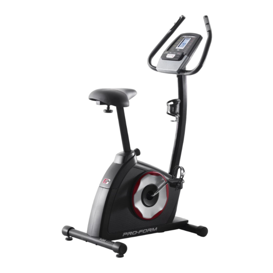
The ance, and toning the body. The 135 CSX exercise bike model number and the location of the serial number provides an impressive selection of features designed decal are shown on the front cover of this manual. -
Page 6: Part Identification Chart
PART IDENTIFICATION CHART Use the drawings below to identify the small parts needed for assembly. The number in parentheses below each drawing is the key number of the part, from the PART LIST near the end of this manual. The number following the key number is the quantity needed for assembly. -
Page 7: Assembly
ASSEMBLY • To hire an authorized service technician to • To identify small parts, see page 6. assemble this product, call 1-800-445-2480. In addition to the included tool(s), assembly • Assembly requires two persons. requires the following tools: one Phillips screwdriver •... - Page 8 3. Set a sturdy piece of packing material under the front of the Frame (1). Orient the Front Stabilizer (2) as indicated by the sticker. Attach the Front Stabilizer to the Frame (1) with two M10 x 68mm Screws (44). Then, remove the packing material.
- Page 9 5. Orient the Rear and Front Upright Covers (19, 20) as shown. Press the Rear and Front Upright Covers (19, 20) together around the Upright (4), and connect them with two M4 x 12mm Screws (57). Then, press the Rear and Front Upright Covers (19, 20) downward onto the Left and Right Shields (21, 22).
- Page 10 7. The Console (5) can use four D batteries (not included); alkaline batteries are recommended. Screws Do not use old and new batteries together or alkaline, standard, and rechargeable batter- ies together. IMPORTANT: If the Console has been exposed to cold temperatures, allow Battery it to warm to room temperature before you Covers...
- Page 11 9. Orient the Seat Post (10) as shown. Loosen the Post Knob (18) a few turns, pull it outward, and insert the Seat Post into the Frame (1). Then, slide the Seat Post (10) upward or down- Adjustment ward to the desired position, and release the Holes Post Knob (18) into one of the adjustment holes in the Seat Post.
- Page 12 11. Identify the Right Pedal (29). Using an adjustable wrench, firmly tighten the Right Pedal (29) clockwise into the right arm of the Crank (40). Firmly tighten the Left Pedal (not shown) Strap counterclockwise into the left arm of the Crank (not shown).
-
Page 13: How To Use The Exercise Bike
HOW TO USE THE EXERCISE BIKE HOW TO ADJUST THE HEIGHT OF THE SEAT HOW TO ADJUST THE PEDAL STRAPS For effective exercise, the seat should be at the proper To adjust the pedal height. As you pedal, there should be a slight bend in straps, first pull the Strap your knees when the pedals are in the lowest position. - Page 14 CONSOLE DIAGRAM FEATURES OF THE CONSOLE You can even connect your MP3 player or CD player to the console sound system and listen to your favorite The advanced console offers an array of features music or audio books while you exercise. designed to make your workouts more effective and enjoyable.
- Page 15 HOW TO USE THE MANUAL MODE The upper display—This display will show your pedal- 1. Turn on the console. ing speed in revolutions per minute (RPM) and your Press any button or begin pedaling to turn on the power output in watts. The console.
- Page 16 5. Measure your heart rate if desired. If your heart rate is not shown, make sure that your hands are positioned as described. Be careful not If there are sheets of to move your hands excessively or to squeeze the plastic on the metal Contacts contacts tightly.
- Page 17 HOW TO USE A PRESET WORKOUT The target zone will be shown in the target Target 1. Turn on the console. meter display. The Zone space between the Press any button or begin pedaling to turn on the flashing bars represents console.
-
Page 18: Fcc Information
HOW TO USE THE SOUND SYSTEM The console can show pedal- ing speed and distance in either To play music or audio books through the console miles or kilometers. The lower sound system while you exercise, plug a 3.5 mm male display will show the selected to 3.5 mm male audio cable (not included) into the jack unit of measurement. -
Page 19: Maintenance And Troubleshooting
MAINTENANCE AND TROUBLESHOOTING MAINTENANCE Locate the Reed Switch (35). Turn the Crank (40) until a Magnet (39) is aligned with the Reed Switch. Loosen, Regular maintenance is important for optimal but do not remove, the two indicated M4 x 16mm performance and to reduce wear. - Page 20 HOW TO ADJUST THE DRIVE BELT See the EXPLODED DRAWING on page 23. Identify the Left and Right Shields (21, 22). Remove If the pedals slip while you are pedaling, even while all of the screws from the Left and Right Shields; there the resistance is adjusted to the highest level, the drive are two sizes of screws in the shields—note which belt may need to be adjusted.
-
Page 21: Exercise Guidelines
EXERCISE GUIDELINES Burning Fat—To burn fat effectively, you must exer- cise at a low intensity level for a sustained period of WARNING: Before beginning this time. During the first few minutes of exercise, your or any exercise program, consult your physi- body uses carbohydrate calories for energy. -
Page 22: Part List
PART LIST Model No. PFEX51915.0 R1215A Key No. Qty. Description Key No. Qty. Description Frame Idler Front Stabilizer Resistance Motor Rear Stabilizer Resistance Cable Upright Reed Switch/Wire Console M4 x 16mm Flange Screw Handlebar Clamp Pulse Sensor Crank Bearing Assembly Handlebar Cap Magnet Water Bottle Holder... -
Page 23: Exploded Drawing
EXPLODED DRAWING Model No. PFEX51915.0 R1215A... -
Page 24: Ordering Replacement Parts
ORDERING REPLACEMENT PARTS To order replacement parts, please see the front cover of this manual. To help us assist you, be prepared to provide the following information when contacting us: • the model number and serial number of the product (see the front cover of this manual) •...
Need help?
Do you have a question about the 135 CSX and is the answer not in the manual?
Questions and answers
How do I replace battery
To replace the battery in a Pro-Form 135 CSX:
1. Remove the screws securing the battery covers.
2. Take off the battery covers.
3. Insert four D alkaline batteries, ensuring they are oriented as shown in the battery compartment diagrams.
4. Reattach the battery covers and secure them with the screws.
5. If the console was exposed to cold temperatures, allow it to warm to room temperature before inserting batteries to prevent damage.
This answer is automatically generated