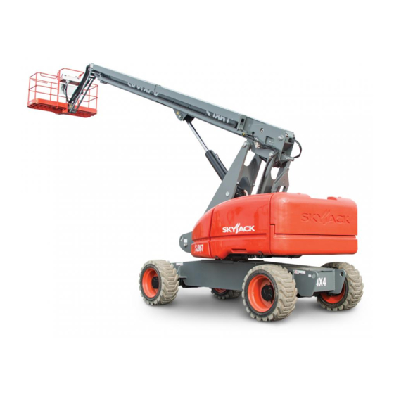
Skyjack SJ86T Operating Manual
Telescopic booms
Hide thumbs
Also See for SJ86T:
- Operation manual (114 pages) ,
- Operating manual (106 pages) ,
- Service manual (255 pages)
Table of Contents
Advertisement
Advertisement
Table of Contents

Related Manuals for Skyjack SJ86T


Summary of Contents for Skyjack SJ86T
- Page 1 OPERATING MANUAL (AS) TELESCOPIC BOOMS MODEL SJ86T 169370AFA November 2018...
- Page 2 This manual is based on Serial Number(s): SJ86T 97 100 001 & Above Please refer to the website (www.skyjack.com) for older Serial Numbers. Skyjack Service Center Parts & Service (Europe) Unit 1 Maes Y Clawdd 3451 Swenson Ave. St. Charles,...
- Page 3 The Safety Alert Symbol identifies important safety messages on MEWP , safety signs in This Safety Alert Symbol means attention! manuals or elsewhere. When you see this symbol, be alert to the possibility of personal Become alert! Your safety is involved. injury or death.
-
Page 4: Table Of Contents
Table of Contents Section 1 - About Your MEWP ........................ 5 Read and Heed ..............................5 Safety Rules ................................6 Section 2 - Familiarization ........................11 Familiarization of Telescopic Boom Series ..................11 Component Identification ........................12 2.2-1 Main Power Disconnect Switch ......................12 2.2-2 Tilt Switch ............................12 2.2-3 Drive Bypass Valve .........................12... -
Page 5: Section 1 - About Your Mewp
SKYJACK warrants each new SJ 8XT series work platform to be free of defective parts and workmanship for the first 24 months. Any defective part will be replaced or repaired by your local SKYJACK dealer at no charge for parts or labor. -
Page 6: Safety Rules
Common sense dictates the use of protective clothing when working on or near machinery. Use appropriate safety devices to protect your eyes, ears, hands, feet and body. Any modifications from the original design are strictly forbidden without written permission from SKYJACK. Electrocution Hazard This MEWP is not electrically insulated. - Page 7 Section 1 - About Your Aerial Platform Safety Rules Safety Precautions Know and understand the safety precautions before going on to next section. WARNING DO NOT • increase the lateral Failure to heed the following safety surface area of the platform. precautions could result in tip over, Increasing the area exposed to falling, crushing, or other hazards leading...
- Page 8 Safety Rules Section 1 - About Your Aerial Platform Safety Precautions (Continued) Know and understand the safety precautions before going on to next section. • DO NOT operate an MEWP • BE AWARE of blind spots that has ladders, scaffolding or when operating the MEWP .
- Page 9 • distribute load the guardrails or materials that unevenly. exceed the confines of the guardrails unless approved by Skyjack. DO NOT DO NOT • use under influence of • operate if MEWP is alcohol or drugs, or if operator’s...
- Page 10 • has alterations or modifications not approved Skyjack recommends the use of a fall restraint by the manufacturer. system to keep an occupant within the confines • has safety devices which have been altered of the platform, and thus not expose the occupant or disabled.
-
Page 11: Section 2 - Familiarization
Section 2 - Familiarization SJ TB Series 2.1 Familiarization of Telescopic Boom Series WARNING MEWP Familiarization should be given only to individuals who are COMPETENT/QUALIFIED And TRAINED to operate an MEWP . Do not operate this MEWP without proper authorization and training. Failure to avoid this hazard could result in death or serious injury. -
Page 12: Component Identification
Control Functions Section 2 - Familiarization 2.2 Component Identification 2.2-3 Drive Bypass Valve The following descriptions are for identification, This valve is located on the inboard side of the drive explanation and locating purposes only. pump and can be identified with a yellow paint mark on it. -
Page 13: Differential Lock Switch
Section 2 - Familiarization Control Functions 2.2-5 Differential Lock Switch 2.2-8 Footswitch This switch is located on the platform control console. The footswitch is located on the floor of the platform. The differential locking system provides more traction When depressed and held, it enables controls on by providing equal drive to each wheel regardless of platform control console. -
Page 14: 10A Platform Load Sensing System
Control Functions Section 2 - Familiarization 2.2-10a Platform Load Sensing System The platform load sensing system is a device that senses for an overload on the platform before the system disables boom and drive functions. This system is active when MEWP is powered on. If the platform is overloaded while in work mode (boom is raised greater than 15 degrees from horizontal or is extended greater than 6 inches), the load sensing system will disable all normal functions and signal the operator with an indicator light and an audible alarm. - Page 15 Section 2 - Familiarization Control Functions 2.2-11 Base Control Console This control console is located in the panel mounted in the control compartment. HOUR METER COUNTER QUARTZ Figure 2-6. Base Control Console Hourmeter - This gauge records accumulated Platform Leveling Override Switch - This switch operating time of engine.
- Page 16 Control Functions Section 2 - Familiarization 2.2-11 Base Control Console (Continued) HOUR METER COUNTER QUARTZ Figure 2-6. Base Control Console Status Indicator Pilot Lights - These lights Off/Base/Platform Key Switch - This three-way indicate operational status and errors in any selector switch allows operator to “...
- Page 17 Section 2 - Familiarization Control Functions 2.2-11 Base Control Console (Continued) HOUR METER COUNTER QUARTZ Figure 2-6. Base Control Console Low Capacity Zone Indicator Light - Indicates MEWP is in “low” platform capacity zone. Refer Table 4.5. High Capacity Zone Indicator Light - Indicates MEWP is in “high”...
- Page 18 Control Functions Section 2 - Familiarization 2.2-12 Platform Control Console This control console is mounted at front guardrail of the platform. It has the following controls: 18 17 Figure 2-7. Platform Control Console Secondary Guarding Electrical (SGE) Reset A. Footswitch - This light illuminates when Button (If Equipped) - This button, when footswitch is depressed.
- Page 19 Section 2 - Familiarization Control Functions 2.2-12 Platform Control Console (Continued) 18 17 Figure 2-7. Platform Control Console Jib Up/Down Switch - This switch controls Torque Switch - This switch selects “ ” low “ ” up or “ ” down movement of jib. or “...
- Page 20 Control Functions Section 2 - Familiarization 2.2-12 Platform Control Console (Continued) 18 17 Figure 2-7. Platform Control Console Low Capacity Zone Indicator Light - Indicates MEWP is in “low” platform capacity zone. Refer Table 4.5. High Capacity Zone Indicator Light - Indicates MEWP is in “high”...
-
Page 21: Visual & Daily Maintenance Inspections
Section 2 - Familiarization Visual & Maintenance Inspection Limit Switches 2.3 Visual & Daily Maintenance Inspections 2.3-2 Electrical Maintaining the electrical components is essential to Begin the visual and daily maintenance inspections good performance and service life of the MEWP . by checking each item in sequence for the conditions listed in this section. - Page 22 Visual & Maintenance Inspection Section 2 - Familiarization Engine Compartment Hydraulic Muffler Pumps Air Filter Battery Main Power Disconnect Switch Engine 2.3-5 Engine Compartment 1. Check battery cases for damage. Ensure all compartment latches are secure and in proper working order. 2.
- Page 23 Section 2 - Familiarization Visual & Maintenance Inspection Engine Compartment Hydraulic Muffler Pumps Air Filter Battery Main Power Disconnect Switch Engine • Hydraulic Pumps • Engine Air Filter Ensure there are no loose or missing Ensure there are no loose or missing parts and there is no visible damage.
- Page 24 Visual & Maintenance Inspection Section 2 - Familiarization Control Compartment Hydraulic Return Filter Hydraulic Tank High Pressure Filter Base Control Console Fuel Tank Brake Manifold Main Manifold Emergency Power Unit 2.3-6 Control Compartment • High Pressure Filter Ensure all compartment latches are Ensure housing is secure and shows no secure and in proper working order.
- Page 25 Section 2 - Familiarization Visual & Maintenance Inspection Base Tie Rod Turret Rotation Limit Switch Steer Cylinder Gear Assembly Drive Axle Oscillating Wheel/Tire Cylinder Assembly Assembly Swing Drive Turret Transportation Rotary Motor Lock Manifold • Fuel Leaks • Oscillating Cylinder Assembly Ensure that there are no fuel leaks.
- Page 26 Ensure all hoses are properly tightened can adversely affect stability. Therefore, and there is no evidence of hydraulic replace tires only with the exact Skyjack- leakage. approved type. Failure to operate with matched approved tires in good condition may result in death or serious injury.
- Page 27 Section 2 - Familiarization Visual & Maintenance Inspection Platform Railing Platform Control Console Manuals Platform Assembly Footswitch 2.3-8 Manuals 2.3-10 Platform Control Console Ensure a copy of operating manual and other Ensure all switches/controllers are returned important documents are enclosed in manual to neutral.
- Page 28 Visual & Maintenance Inspection Section 2 - Familiarization Wear Pad Boom Cable Springs Cable Springs Wear Pad Rotary Actuator E-Chain Lift Cylinder 2.3-11 Rotary Actuator Ensure all bolts and pins are properly Ensure there are no loose or missing parts tightened.
- Page 29 Section 2 - Familiarization Visual & Maintenance Inspection Wear Pad Boom Cable Springs Cable Springs Wear Pad Rotary Actuator E-Chain Lift Cylinder • Cables Ensure there are no loose or missing parts with no signs of visible damage. Ensure that nuts are not loose and are locked together.
- Page 30 Visual & Maintenance Inspection Section 2 - Familiarization Hydraulic Generator Flashing Amber Light Work Light Glazier Tray 2.3-15 Optional Equipment/Attachments • Hydraulic Generator (If Equipped) Ensure there are no loose or missing parts with no signs of visible damage. Ensure all hoses are properly tightened and there is no evidence of hydraulic leakage.
-
Page 31: Function Tests
Section 2 - Familiarization Function Tests HOUR METER Base Control COUNTER QUARTZ Console Start/Function Enable/ Emergency Power Switch Emergency Stop Off/Base/Platform Key Switch 2.4 Function Tests 2.4-1 Test Main Power Disconnect Switch Function tests are designed to discover any malfunctions In engine compartment, turn main power before MEWP is put into service. - Page 32 Function Tests Section 2 - Familiarization HOUR METER Base Control COUNTER QUARTZ Console Start/Function Enable/ Emergency Power Switch Emergency Stop Off/Base/Platform Key Switch • Test Emergency Stop 4. Hold “ ” start/function enable/ emergency power switch in function 1. Push in “ ”...
- Page 33 Section 2 - Familiarization Function Tests Capacity Zone Border Light HOUR METER COUNTER QUARTZ High Capacity Zone Indicator Light Low Capacity Zone Indicator Light • Test Base Capacity Zone Indicator Lights NOTE To perform this function test, ensure there is sufficient space to fully raise and extend boom.
- Page 34 Function Tests Section 2 - Familiarization HOUR METER Base Control COUNTER QUARTZ Console Start/Function Enable/ Emergency Power Switch Emergency Stop Off/Base/Platform Key Switch • Test Emergency Power 4. On base control console, turn off/base/ platform key switch to “ ” platform 1.
- Page 35 Section 2 - Familiarization Function Tests Platform Control Emergency Stop Console Drive/Steer Controller Fall Protection Anchorage Fall Protection Anchorage Footswitch • Test Off/Base/Platform Switch 6. Select “ ” start position from engine start/on/off switch until engine starts. 1. Ensure both “ ”...
- Page 36 Function Tests Section 2 - Familiarization Platform Control Emergency Stop Console Drive/Steer Controller Fall Protection Anchorage Fall Protection Anchorage Footswitch 3. Do not start engine. WARNING 4. Select generator on/off switch to off DO NOT operate any control on platform position (if equipped).
- Page 37 Section 2 - Familiarization Function Tests High Capacity Zone Indicator Light Low Capacity Zone Capacity Zone Border Indicator Light Light • Test Platform Capacity Zone Indicator Lights NOTE To perform this function test, ensure there is sufficient space to fully raise and extend boom.
- Page 38 Function Tests Section 2 - Familiarization Emergency Power Engine Start/On/ Emergency Stop Switch Off Switch Horn Drive/Steer Controller Platform Leveling Override Switch • Test Engine Start/On/Off Switch • Test Manual Platform Leveling 1. Ensure engine is running. 1. Start engine. 2.
- Page 39 Section 2 - Familiarization Function Tests Emergency Power Engine Start/On/ Emergency Stop Switch Off Switch Horn Drive/Steer Controller Platform Leveling Override Switch • Test Driving Function • Test Driving Speed 1. Ensure path of intended motion is clear. 1. Depress and hold footswitch. 2.
- Page 40 Function Tests Section 2 - Familiarization Emergency Power Engine Start/On/ Emergency Stop Switch Off Switch Horn Drive/Steer Controller Platform Leveling Override Switch • Test Emergency Power • Test Horn 1. Push “ ” horn pushbutton. CAUTION Result: Horn should sound. When operating on auxiliary power, do not operate more than one function •...
- Page 41 Section 2 - Familiarization Function Tests Emergency Power Engine Start/On/ Emergency Stop Switch Off Switch Horn Drive/Steer Controller Platform Leveling Override Switch • Test Differential Lock Switch WARNING Before engaging differential lock, ensure drive/steer controller is in neutral position. 1. On platform control console, push d i f f e r e n t i a l l o c k s w i t c h f o r w a r d “...
- Page 42 Function Tests Section 2 - Familiarization Emergency Power Engine Start/On/ Switch Off Switch Emergency Stop Horn Reset Button Drive/Steer Controller Platform Leveling Override Switch • Test Secondary Guarding Electrical (SGE) 6. Press the sensor bar for more than 1 (If Equipped) second and then release.
- Page 43 Section 2 - Familiarization Function Tests Emergency Power Engine Start/On/ Switch Off Switch Emergency Stop Horn Reset Button Drive/Steer Controller Platform Leveling Override Switch 11. Press the sensor bar for more than 1 Result: The function will stop and the second and then release.
- Page 44 Function Tests Section 2 - Familiarization Oscillating Axle - Unlocked Oscillating Axle - Locked • Test Oscillating Axles • Test Cables NOTE WARNING Cables have to be tested daily. DO NOT operate any control on platform control console without proper fall 1.
-
Page 45: Winching And Towing Procedure
Section 2 - Familiarization Procedures 2.5 Winching and Towing Procedure Position MEWP on a firm and level surface. This section provides the operator with the winching and towing procedure, which includes instructions on Chock or block wheels to prevent MEWP from how to manually release the brakes. - Page 46 Procedures Section 2 - Familiarization 2.5-1 To Release Brakes Manually Brakes must be manually disengaged for winching or CAUTION towing. Do not release brakes before disengaging WARNING drive motor! Do not manually disengage brakes if MEWP is on a slope. Push in black brake valve plunger (item 3).
-
Page 47: Emergency Lowering Procedures
Section 2 - Familiarization Procedures 2.6 Emergency Lowering Procedures At Platform Control Console: This section guides the operator on how to use Ensure engine is off. emergency lowering system. This system allows platform lowering in the event of an emergency or engine malfunction. - Page 48 Notes SJ 86T Page 48 December 2007...
-
Page 49: Section 3 - Operation
MEWP . NOTE • The operator must be familiar with employer’s work Refer to Skyjack’s website www.skyjack.com rules and related government regulations and be for latest service bulletins prior to performing able to demonstrate the ability to understand and frequent or yearly inspections. -
Page 50: Major Components
Major Components Section 3 - Operation 3.2 Major Components Platform Control Console Fly Boom Mid Boom Platform Jib (SJ86T only) E-Chain Main Boom Lift Cylinder Engine Compartment Control Compartment Base Base Control Console Turret SKYJACK 8XT Telescopic Boom SJ 86T... -
Page 51: Major Assemblies
The telescoping boom mechanism uses two double- acting hydraulic cylinders with holding valves to control vertical movement. Cables are used to extend the fly boom section. The SJ86T model is equipped with a 150 cm (60 in.) boom jib, controlled by a double-acting hydraulic cylinder. -
Page 52: Component Identification (Optional Equipment/Attachments)
Component Identification (Special Options) Section 3 - Operation 3.5 Component Identification (Optional 3.5-3 Flashing Amber Light (If Equipped) The flashing amber light is located on top of the turret Equipment/Attachments) of the MEWP . The following descriptions are for identification, explanation and locating purposes only. - Page 53 Section 3 - Operation Component Identification (Special Options) Sensor Bar - This bar is located in front of the 3.5-5 Glazier Tray (If Equipped) platform control console. When pressure is The tray is installed on the front side of the platform. applied to the sensor bar, it interrupts/halts all functions.
-
Page 54: Operator's Responsibility
Operator’s Responsibility Section 3 - Operation 3.6 Operator’s Responsibility Repairs to the MEWP may only be made by competent/ qualified repair personnel. After repairs are completed, It is the responsibility of the operator, prior to each work the operator must perform visual and daily maintenance shift, to perform the following: inspections &... -
Page 55: Start Operation
Section 3 - Operation Start Operation 3.7 Start Operation • has been tagged or locked out for non-use or repair. Carefully read and completely understand the Operating Manual and all warnings and instruction labels Failure to avoid these hazards could result in death (refer to Section 5 - Labels) on the MEWP . - Page 56 Start Operation Section 3 - Operation 3.7-2 To Rotate Platform Using Base Control Activate function enable “ ” by selecting and Console holding start/function enable/emergency power switch to function enable position. Activate function enable “ ” by selecting and holding start/function enable/emergency power Push main boom raise/lower switch to either switch to function enable position.
- Page 57 Section 3 - Operation Start Operation 3.7-9 To Activate Platform Control Console Select desired engine RPM using throttle switch: “ ” high or “ ” low. In engine compartment, turn main power disconnect switch to “ ” on position. WARNING On base control console, turn off/base/platform •...
- Page 58 Start Operation Section 3 - Operation 3.7-11 To Steer Using Platform Control Console 3.7-15 To Rotate Platform Using Platform Control Console Depress and hold footswitch. Depress and hold footswitch. Press rocker on top of drive/steer controller in this On platform rotation switch, select “ ”...
- Page 59 Section 3 - Operation Start Operation 3.7-18 To Rotate Turret Using Platform Control 3.7-21 Shutdown Procedure Console Completely retract boom and lower platform. WARNING Push in “ ” emergency stop button on platform When rotating the turret, ensure that there control console and on base control console.
-
Page 60: Refueling Procedure
Refueling Procedure Section 3 - Operation 3.8 Refueling Procedure 3.8-1 Refuelling (Gasoline or Diesel) This section provides the operator with the procedure IMPORTANT on how to refuel the engine. Use unleaded gasoline or ultra low sulfur diesel as indicated on fuel tank. WARNING Failure to heed the following safety Ensure engine and all systems are turned off and... -
Page 61: Loading/Unloading
Section 3 - Operation Loading/Unloading 3.9 Loading/Unloading Remove all loose items. Know and heed all national, state/provincial and local Anchor down MEWP to transport surface using rules which apply to transporting of MEWPs. tie-down points (refer to Figure 3-5). Only competent/qualified personnel shall operate the MEWP during loading/unloading. - Page 62 Loading/Unloading Section 3 - Operation 3.9-2 Locking the Turret Clear platform of all personnel, tools and materials. Ensure that turret is positioned so that turret transportation lock tube (item 2 – Figure 3-7) is WARNING aligned into one of two turret locking points on When lifting the MEWP, lifting devices the chassis.
-
Page 63: Chassis Tilt
Section 3 - Operation Chassis Tilt 3.10 Chassis Tilt 3.10-1 Counterweight Uphill If the MEWP becomes tilted with the counterweight uphill This section guides the operator with regard to (refer to Figure 3-9) follow the steps below to return to recovering from an inclined position. -
Page 64: Technical Diagrams
-4.5 -1.5 10.5 13.5 16.5 19.5 22.5 25.5 Figure 3-11. Reach Diagram - SJ86T 28 ft. 3 in. (8.61 m) 105 in. 76 ft. 10 in. (23.42 m) 2667 mm 65 degrees 66 in. (167.64 cm) 12 degrees 10 ft. 8 in. (3.25 m) 60 in. - Page 65 0.28 m 12.34 m 13 m Figure 3-12b. Dimensions - SJ86T WARNING Do not raise the platform in work mode if it is not on a firm, level surface. Axle oscillation free (travel mode) - drive speed 4.83 km/h max.
- Page 66 Notes SJ 86T Page 66 December 2007...
-
Page 67: Section 4 - Tables
Section 4 Tables Table 4.1 Standard and Optional Features MODEL SJ 86T S T A N D A R D E Q U I P M E N T 12 Volt DC emergency power 1.68 m jib 0.91 m x 2.44 m platform Base controls Continuous drive and steer directional sensing Diesel engine... - Page 68 Tables Section 4 Table 4.2a Specifications and Features MODEL SJ 86T Total platform length (outside) 1.83 m / 2.44 m Total platform depth (outside) 0.91 m Working 28.04 m Platform elevated 26.21 m Drive driveable at all heights Stowed Overall with platform 12.95 m Outside std.
- Page 69 Max. Oil Temp. +93°C (200°F) Limits Alternates HVLP T46 (Summer) (Note: Cold weather starting temperatures can be improved with Skyjack options. Please consult your nearest Skyjack HVLP T42 (Winter) service center.) Tank Capacity 223.3 L Sound Pressure Level (ISO 3744)
- Page 70 Tables Section 4 Table 4.3 Owner’s Annual Inspection Record Model Number: _________________ Serial Number:__________________ 20__ 20__ 20__ 20__ 20__ 20__ 20__ 20__ 20__ 1001AB This decal is located on the control compartment cowling. It must be completed after an annual inspection has been completed.
- Page 71 Intermixing tires of different types or using tires of types other than those originally supplied with this equipment can adversely affect stability. Therefore, replace tires only with the exact Skyjack- approved type. Failure to operate with matched approved tires in good condition may result in death or serious injury.
- Page 72 Hourmeter Reading: Operator's Name (Printed): Date: Time: Operator's Signature: Each item shall be inspected using the appropriate section of the Skyjack operating manual. As each item is inspected, check the appropriate box. - PASS - FAIL - REPAIRED - NOT APPLICABLE...
-
Page 73: Section 5 - Labels
Section 5 Labels Label Legend Safety Red Safety Red indicates DANGER. Safety Orange Safety Orange indicates WARNING. Safety Yellow Safety Yellow indicates CAUTION. Safety Green Safety Green indicates emergency lowering. Safety Blue Safety Blue indicates safety information. SJ 86T December 2007 Page 73... - Page 74 Warning - Do Not Alter Do not alter or disable limit switches or other safety devices. Model Number* Product Identifier *Model number will vary, may not be as shown. Skyjack Logo Skyjack Lift Points Optional lifting points required. Only use these points for lifting.
- Page 75 Section 5 Labels Engine Side (Continued) Label Pictorial Description Body Crushing Hazard Danger - Body crushing hazard Tie Down Points Only use these points for tying down. Tie Down Points (If equipped) Only use these points for tying down. Lift Points Only use these points for lifting.
- Page 76 Labels Section 5 Engine Side (Continued) 12 11 Label Pictorial Description Sound Power Level Guaranteed maximum sound power level Foam-filled Tire Indicates foam-filled tire. Wheel Specifications Refer to manual for wheel type, offset, pressure and torque. Caution Tape Stripe Caution stripe Tie Down Points Only use these points for tying down.
- Page 77 Section 5 Labels Engine Compartment Label Pictorial Description Main Power Disconnect Main power disconnect lever SJ 86T December 2007 Page 77...
- Page 78 Labels Section 5 Engine Compartment Label Pictorial Description Winching/Towing/Pushing Procedure Refer to Operating manual. 1. Block or chock wheels to prevent MEWP from rolling. 2. Turn main power disconnect switch to off position. At engine side: 3. Locate bypass valve (marked with yellow colour) on inboard side of drive pump.
- Page 79 Section 5 Labels Front Side Turret - Bottom View Label Pictorial Description 4x4 (If Equipped) Product identifier - 4 wheel drive Warning - Do Not Alter Do not alter or disable limit switches or other safety devices. Serial Plate* Product identification and specifications *Serial plate will vary, may not be as shown.
- Page 80 Section 5 Control Side Label Pictorial Description Lift Points Optional lifting points required. Only use these points for lifting. Skyjack Logo Skyjack Diesel Use ultra low sulfur fuel only. No Smoking Do not smoke near this location. Model Number* Product Identifier *Model number will vary, may not be as shown.
- Page 81 Section 5 Labels Control Side (Continued) Label Pictorial Description Body Crushing Hazard Danger - Body crushing hazard Crushing Hazard Danger - Crushing hazard Tie Down Points Only use these points for tying down. Tie Down Points (If equipped) Only use these points for tying down. Lift Points Only use these points for lifting.
- Page 82 Labels Section 5 Control Side (Continued) 14 13 Label Pictorial Description Sound Power Level Guaranteed maximum sound power level Foam-filled Tire Indicates foam-filled tire. Wheel Load* Indicates rated wheel load. *Wheel load will vary over different MEWPs. Wheel Specifications Refer to manual for wheel type, offset, pressure and torque. Caution Tape Stripe Caution stripe SJ 86T...
- Page 83 Section 5 Labels Control Side (Continued) Label Pictorial Description Annual Inspection Ensure that work platform has received annual inspection prior to operation. Emergency Lowering Procedure Refer to Operating manual. 1. A) Ensure engine is off. B) Pull out “ ” emergency stop button. 2.
- Page 84 Labels Section 5 Platform Views Label Pictorial Description No Jewelry Caution - Do not wear jewelry. Operator’s Daily Inspection Refer to the Operating manual. Perform visual inspection and function tests at the beginning of each shift. Refer to Table 4.7 Operator’s Daily Inspection Checklist. Platform Capacity* Rated work load in each configuration.
- Page 85 Section 5 Labels Control Compartment Label Pictorial Description Base Control Console Push “ ” breaker back in to reset. Select and hold “ ” to enable error blink code for engine control unit (ECU). Read “ ” operating manual. Select “ ”...
- Page 86 Replace hydraulic fluid with Shell Tellus T46 or approved alternate (see Table 4.2b). (Note: Cold weather starting temperatures can be improved with Skyjack options. Please consult your nearest Skyjack service center.) Hydraulic Oil Level Indicates minimum/maximum oil level. SJ 86T...
- Page 87 Section 5 Labels Control Compartment (Continued) Label Pictorial Description Winching/Towing/Pushing Procedure Refer to Operating manual. 1. Block or chock wheels to prevent MEWP from rolling. 2. Turn main power disconnect switch to off position. At engine side: 3. Locate bypass valve (marked with yellow colour) on inboard side of drive pump.
- Page 88 Labels Section 5 Control Compartment (Continued) Label Pictorial Description Diesel Use ultra low sulfur fuel only. No Smoking Do not smoke near this location. Connect AC Supply Connect AC supply here. SJ 86T Page 88 December 2007...
- Page 89 Section 5 Labels Rear Side no step Label Pictorial Description Warning - No Step No step warning Fall Protection Anchorage Anchor safety belt/harness tethers here. Rated for one (1) person per anchorage. Platform Capacity* Rated work load in each configuration. Rated work load includes the weight of both personnel and material, and maximum number of people in each configuration.
- Page 90 Labels Section 5 Rear Side (Continued) no step Label Pictorial Description Manual Box Indicates location of operating manual. Hazard Identification Refer to Section 1: Safety Rules. Read and understand outlined risks associated with this work platform prior to operation. Model Number* Product Identifier *Model number will vary, may not be as shown.
- Page 91 Rear Side (Continued) no step Label Pictorial Description 4x4 (If Equipped) Product identifier - 4 wheel drive Skyjack Logo Skyjack Body Crushing Hazard Danger - Body crushing hazard EWPA Clearance Requirements Clearance requirements for operating non-insulated mobile plant, including elevating work platforms near power lines.
- Page 92 Labels Section 5 Platform Control Console Label Pictorial Description SGE Reset (If Equipped)/Work Light (If Equipped)/Start Engine/Generator (If Equipped) Select to reset SGE (if equipped). Select to enable work light (if equipped). Push and hold “ ” to start engine and then return to “ ”...
- Page 93 Section 5 Labels Platform Control Console Continued Label Pictorial Description Boom Speed Adjuster Dial Adjust dial to vary speed of fly boom extension/retraction, jib raising/ lowering and platform rotation movements Boom/Turret Controller Push and hold controller in this direction “ ”...
- Page 94 Labels Section 5 Platform Control Console (Continued) Label Pictorial Description Boom/Jib/Platform Controls Select “ ” to rotate platform to the left or “ ” to the right. Select “ ” to tilt platform up or “ ” to tilt platform down. Select “...
- Page 95 Section 5 Labels Platform Railing Label Pictorial Description Crushing Hazard Danger - Crushing hazard Connect AC Supply Connect AC supply here. Warning - Do Not Alter Do not alter or disable limit switches or other safety devices. Footswitch Enable (On/Off) Depress and hold footswitch to enable platform function.
- Page 96 Labels Section 5 Optional Equipment/Attachments Label Pictorial Description Panel Cradle Capacity - Dual Load (Glazier Kit) Refer to Operating manual. Panel cradle option derates the capacity of the aerial platform. Do not use with any other platform option/attachment. This label overrides all rated work loads of this aerial platform.
- Page 98 www.skyjack.com...
Need help?
Do you have a question about the SJ86T and is the answer not in the manual?
Questions and answers