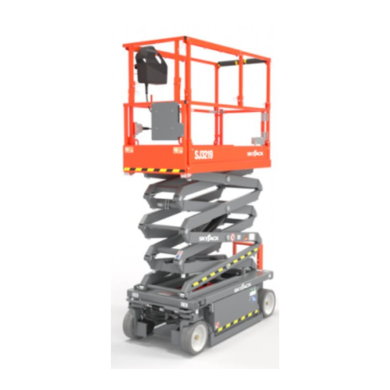
Skyjack SJ3219 Service Manual
Dc electric scissors
Hide thumbs
Also See for SJ3219:
- Operating manual (89 pages) ,
- Service manual (114 pages) ,
- Operation manual (114 pages)

Related Manuals for Skyjack SJ3219


Summary of Contents for Skyjack SJ3219
- Page 1 SERVICE MANUAL SJ3215, SJ3219 DC ELECTRIC SCISSORS 212508ADA September 22, 2021 ANSI/CSA, CE, AS, KC...
- Page 2 This manual is for MEWPs with serial numbers: SJ3215 and SJ3219: A/B100 000 001 to A/B100 999 999 Please refer to the website (www.skyjack.com) for contact information, other serial numbers, the most recent technical manuals, and USB software.
- Page 3 It may also be used to alert against unsafe practices. IMPORTANT IMPORTANT indicates a procedure essential for safe operation and which, if not followed, may result in a malfunction or damage to the MEWP . SJ3215, SJ3219 212508ADA...
- Page 4 Notes SJ3215, SJ3219 212508ADA...
-
Page 5: Table Of Contents
Specifications & Features - KC ............37 SJ3215, SJ3219... - Page 6 Hydraulic Schematics - SJ3219 ANSI/CSA ........
- Page 7 Charger Maintenance ............116 SJ3215, SJ3219...
- Page 8 5.4-10 Callibration Fault Codes ............153 SJ3215, SJ3219...
-
Page 9: Section 1 - Scheduled Maintenance
2 years or 3000 hours, whichever occurs first. Any defective part will be replaced or repaired by your local Skyjack dealer at no charge for parts or labor. In addition, all products have a 5-year structural warranty. -
Page 10: Maintenance And Inspection Schedule
MEWP . relative law provisions obtaining in the country. Consult SKYJACK’s Service Department for optional Before attempting any repair work, disconnect the tires specifications and installation. main power conenctors. -
Page 11: Hydraulic System & Component Maintenance And Repair
The use of cloth to strain the system. Air in the system can cause damage oil should be avoided to prevent lint from getting to the components and noisy or erratic system into the system. operation. SJ3215, SJ3219 212508ADA... -
Page 12: Maintenance Hints
Dirty, dusty, high moisture environments may cause the hydraulic system to be contaminated more quickly. 2. Maintain a sufficient quantity of clean hydraulic oil of the proper type and viscosity in the hydraulic reservoir. 3. Keep all connections tight. SJ3215, SJ3219 212508ADA... -
Page 13: About This Section
MEWP parked on a flat and level surface ▪ column. Disconnect the batteries by disconnecting the ▪ Legend main power connectors. Pass Repair any damaged or malfunction ▪ components before operating MEWP . Not applicable Keep records on all inspections. ▪ SJ3215, SJ3219 212508ADA... -
Page 14: Owner's Annual Inspection Record
The Owner’s annual inspection record is located on the scissor assembly. It must be filled out after an annual inspection has been completed. Do not use the MEWP if an inspection has not been recorded in the last 13 months. SJ3215, SJ3219 212508ADA... -
Page 15: Frequent/Periodic/Annual/Pre-Delivery Inspection Checklist
Comments: The undersigned has made sure that all areas in the list have received an inspection. The undersigned has told the machine owner of all inconsistencies in the inspection and corrected them before machine operation. Owner: User: SJ3215, SJ3219 212508ADA... -
Page 16: General Inspections
Section 1 – Scheduled Maintenance General inspections 1.5-1 Service Bulletins 1.5 General inspections Go to www.skyjack.com and use your machine’s Do an inspection of the MEWP in this sequence: serial number to find related open service bulletins. WARNING 1.5-2 Annual Inspections Do not operate a MEWP that does not function Do a check on the machine’s service record to find... -
Page 17: Base Inspection
Base inspection Section 1 – Scheduled Maintenance Example model SJ3219 Battery Tray Example model SJ3219 Hydraulic Tray 1. Do an inspection of the battery case for 1.6 Base inspection damage. Pothole protection device 2. Make sure all the battery connections are tight. - Page 18 Make sure there is no visible damage. ▪ Steer linkages ▪ Do not use tires other than the tires that Skyjack specifies for this MEWP . Do not mix different types Make sure there are no loose or missing ▪...
- Page 19 Make sure the castle nuts are in position ▪ and are tight. Figure 01 Make sure the cotter pins are correctly ▪ installed. If the cotter pin is not installed, refer to 2.11 ▪ Torque Specifications for proper torque information. SJ3215, SJ3219 212508ADA...
- Page 20 Section 1 – Scheduled Maintenance General inspections Example model SJ3219 ANSI/CSA SJ3219 CE, AS & KC Manifolds Motor controller ▪ Hydraulic tank Make sure the motor controller is correctly ▪ Make sure the hydraulic filler cap closes tightly. ▪ attached, and there is no visible damage.
- Page 21 General inspections Section 1 – Scheduled Maintenance Example model SJ3219 ANSI/CSA Example model SJ3219 CE, AS & KC Main power disconnect switch Base weldment Turn the main power disconnect switch to the off Make sure that the base shows no signs of visible ▪...
-
Page 22: Scissors Inspection
Make sure that the sliders and rollers on the left ▪ and right side of the MEWP are correctly attached. Make sure there is no visible damage. ▪ Make sure there is no dirt or blockages in the ▪ slider’s and roller’s travel paths. SJ3215, SJ3219 212508ADA... - Page 23 Area is clear of dust or metal shavings ▪ immediately removed from service and repaired Pin retainers are installed by a qualified technician. Speak to the Skyjack ▪ service department for directions on how to repair the unit. 1. Do an inspection of the scissor pin connections.
- Page 24 Examples of damaged pin connections: Broken retainer bolt Center Pin - Outer Rust around the pin Rotated pin Rust around pin boss Center Pin - Middle Thrust washer Broken pin boss Stress cracks Center Pin - Inner SJ3215, SJ3219 212508ADA...
- Page 25 Cracks in welds or the surrounding metal, or rust ▪ forming in the area. Bearing block degradation Broken, missing, or Cracks in weld or loose retainers or bolts surrounding metal, rust in the area Note: weld intentionally not located at bolt area SJ3215, SJ3219 212508ADA...
-
Page 26: Platform Inspection
Fall-protection anchorages components. Make sure that the fall-protection anchorages are ▪ Make sure the lock-pins are correctly attached. ▪ correctly installed. 2. Use the MEWP ladder to exit the platform. Make sure there is no visible damage. ▪ SJ3215, SJ3219 212508ADA... -
Page 27: Function Tests
Before you do the function tests, look for the ▪ operation manual with the same serial number as your MEWP . The operation manual has the instructions on which tests to do and how to do them correctly and successfully. SJ3215, SJ3219 212508ADA... - Page 28 Notes SJ3215, SJ3219 212508ADA...
-
Page 29: Section 2 - Maintenance Tables And Diagrams
MEDIUM 90°, FEMALE, 37° JIC, SWIVEL 100R13 SHORT 90°, FEMALE, 37° JIC, SWIVEL SHORT 90°, FEMALE, 37° JIC, SWIVEL 100R17 FEMALE, 37° JIC, SWIVEL REUSABLE MALE PIPE THREAD FITTING 300 PSI REUSABLE MALE PIPE THREAD FITTING NO FITTING 300 PSI SJ3215, SJ3219 212508ADA... - Page 30 FEMALE, 37° JIC, SWIVEL 100R19 MEDIUM 90°, FEMALE, 37° JIC, SWIVEL FEMALE, 37° JIC, SWIVEL 100R19 LONG 90°, FEMALE, 37° JIC, SWIVEL FEMALE, 37° JIC, SWIVEL 100R19 LONG 90°, FEMALE, SAE ORFS, SWIVEL FEMALE, SAE ORFS, SWIVEL 100R15 SJ3215, SJ3219 212508ADA...
-
Page 31: Torque Specifications For Fasteners (Us)
1460 3160 2360 1 1/2-6 ft-lb 1180 2630 1979 4284 3200 1/2-20 ft-lb 2200 1640 3560 2660 1 1/2-12 1329 2983 2224 4827 3606 NOTE: Lubed includes lubricants such as lubrizing, oil, grease, or uncured Loctite. 1374AA SJ3215, SJ3219 212508ADA... -
Page 32: Torque Specifications For Fasteners (Metric)
1468 1101 2101 1576 M33 x 3.50 1990 1493 2849 2137 ft-lb 1886 1415 2699 2024 M36 x 4.00 2557 1918 3659 2744 NOTE: Lubed includes lubricants such as lubrizing, oil, grease, 1375AB or uncured Loctite. SJ3215, SJ3219 212508ADA... -
Page 33: Torque Specifications For Hydraulic Couplings & Hoses
Min. Max. Min. Max. Min. Max. Min. Max. 1/4" 6.75 1/4" 3/8" 3/8" 1/2" 27.66 1/2" 5/8" 46.33 5/8" 3/4" 72.33 3/4" 1" 100.5 1" 1 1/4" 101.5 1 1/4" 1 1/2 1 1/2 2" 2" 1276AA SJ3215, SJ3219 212508ADA... -
Page 34: Specifications & Features - Ansi/Csa
SHELL NATURELLE HF-E 32 Tank Capacity (Liters) 11.3 L (3 gal) Sound Pressure Level at Platform Level Does not exceed: 70 db(A) * Weight with standard 0.9 m extension platform. Refer to serial nameplate for specific applications. 2002AB SJ3215, SJ3219 212508ADA... -
Page 35: Specifications & Features - Ce
Type SHELL NATURELLE HF-E 32 Tank Capacity (Liters) 11.3 L Sound Pressure Level at Platform Level Does not exceed: 70 db(A) * Weight with standard 0.9 m extension platform. Refer to serial nameplate for specific applications. 2003AA SJ3215, SJ3219 212508ADA... -
Page 36: Specifications & Features - As
Type SHELL NATURELLE HF-E 32 Tank Capacity (Liters) 11.3 L Sound Pressure Level at Platform Level Does not exceed: 70 db(A) * Weight with standard 0.9 m extension platform. Refer to serial nameplate for specific applications. 2004AA SJ3215, SJ3219 212508ADA... -
Page 37: Specifications & Features - Kc
Type SHELL NATURELLE HF-E 32 Tank Capacity (Liters) 11.3 L Sound Pressure Level at Platform Level Does not exceed: 70 db(A) * Weight with standard 0.9 m extension platform. Refer to serial nameplate for specific applications. 2005AA SJ3215, SJ3219 212508ADA... -
Page 38: Maximum Platform Capacities (Evenly Distributed)
1.5˚ × 3.5˚ 272 kg 113 kg 1 Person 12.5 m/s 1 Person 200 N 0 m/s 2 Persons 400 N 3219 1.5˚ × 3.5˚ 227 kg 113 kg 1 Person 12.5 m/s 1 Person 200 N 2006AA SJ3215, SJ3219 212508ADA... -
Page 39: Floor Loading Pressure
Note: The LCP or OFL that an individual surface can withstand varies from structure to structure and is generally determined by the engineer or architect for that particular structure. generally determined by the engineer or architect for that particular structure. SJ3215, SJ3219 212508ADA... -
Page 40: Torque Specifications
Port Size Torque (lb-ft) max Torque (lb-in) max Torque (Nm) max 4.07 13.56 20.34 20.34 33.9 33.9 40.68 47.46 Newton-meter = Nm Pound-foot = lb-ft Pound-inch = lb-in 2008AB Additional Torque Specifications may be found in Section 5. SJ3215, SJ3219 212508ADA... -
Page 41: Section 3 - System Component Identification And Schematics
Section 3 – System Component Identification and Schematics SJ3215, SJ3219 212508ADA... -
Page 42: Electrical Symbol Chart
TILT SWITCH TRANSISTOR SINGLE POLE VACUUM POTENTIOMETER SINGLE THROWN LEVEL SENSOR SWITCH RELAY DOUBLE POLE TEMPERATURE SINGLE POLE DOUBLE POLE DOUBLE THROW SWITCH DOUBLE THROW SINGLE THROW RELAY RELAY RELAY TRIPLE POLE RHEOSTAT DIODE DOUBLE THROW RELAY SJ3215, SJ3219 212508ADA... -
Page 43: Hydraulic Symbol Chart
THREE WAY VALVE MOTOR OPEN PORT CLOSED VALVE THREE POSITION TWO POSITION TWO POSITION FOUR WAY TWO WAY THREE WAY VALVE CLOSED CENTER NORMALLY CLOSED PORT OPEN VALVE PRESSURE PILOT LINES Dashed MAIN LINES Solid TRANSDUCER SERVO SJ3215, SJ3219 212508ADA... -
Page 44: Wire Number And Color Code
This table is to be used as a wire number/color reference for electrical drawings and schematics. All wire numbers will retain their original color coding, for example if wire 7 is red, wire 7A, 7B, and 7C will also be red. SJ3215, SJ3219 212508ADA... -
Page 45: Hydraulic Parts List
(SJ3215 ANSI/CSA) 226497 MANIFOLD, Main (SJ3215 CE, AS & KC) 226479 MANIFOLD, Main (SJ3219 ANSI/CSA) 226481 MANIFOLD, Main (SJ3219 CE, AS & KC) 138021 MANIFOLD, Free-Wheel 212912 MANIFOLD, Holding 209218 MANIFOLD, Brake Release (CE, AS & KC) 310056 ORIFICE, Steer - 0.040"... -
Page 46: Electrical Parts List
LIGHT, Base - Emergency Stop/Overload 217934 TRANSDUCER, Pressure - 3000 PSI (SJ3219) 217933 TRANSDUCER, Pressure - 2000 PSI (SJ3215) 210051 SWITCH, Main Disconnect 147054 SWITCH, Lift/Lower 207741 SWITCH, Lift/Off/Drive 147053 SWITCH, Platform - Emergency Stop 220494 SWITCH, SGLE SJ3215, SJ3219 212508ADA... - Page 47 SWITCH, Left S7-6 159067 SWITCH, Enable 147054 SWITCH, Horn 149536 SWITCH, Key - Idle/Platform/Base (ANSI/CSA, AS & KC) 147057 SWITCH, Key - Idle/Platform/Base (CE) 115574 SWITCH, Torque 147053 SWITCH, Base - Emergency Stop 212204 SWITCH, Emergency Lowering SJ3215, SJ3219 212508ADA...
-
Page 48: Platform Control Box Wiring
GREY TO S7 JOYSTICK PROP . OUT ORANGE/BLACK BLUE 5V SUPPLY GREEN YELLOW PIN NO. COLOUR CIRCUIT NO. WHITE BLUE ORANGE BLACK BLUE/WHITE GREEN/WHITE GREEN NOT USED WHITE/BLACK RED/BLACK ORANGE/BLACK GREEN/BLACK TIED BACK BLUE/BLACK BLACK/WHITE RED/WHITE M212617AC SJ3215, SJ3219 212508ADA... -
Page 49: Platform Control Box Wiring - Sgle
WHITE/BLACK 0V SUPPLY GREY ORANGE/BLACK PROP . OUT BLUE 5V SUPPLY GREEN YELLOW PIN NO. COLOUR CIRCUIT NO. WHITE BLUE ORANGE BLACK BLUE/WHITE GREEN/WHITE GREEN NOT USED WHITE/BLACK RED/BLACK ORANGE/BLACK GREEN/BLACK TIED BACK BLUE/BLACK BLACK/WHITE RED/WHITE M220967AA SJ3215, SJ3219 212508ADA... -
Page 50: Base To Platform Control Cable
Section 3 – System Component Identification and Schematics Base to Platform Control Cable 3.8 Base to Platform Control Cable CAVITY NO. COLOUR CIRCUIT NO. WHITE BLUE ORANGE BLACK BLUE/WHITE GREEN/WHITE GREEN NOT USED WHITE/BLACK RED/BLACK ORANGE/BLACK GREEN/BLACK BLUE/BLACK BLACK/WHITE RED/WHITE M212573AB SJ3215, SJ3219 212508ADA... -
Page 51: Base Control Wiring
PIN 1 - 07 (RED) PIN 2 - 05 (PURPLE/BLACK) PIN 3 - 13A (ORANGE) PIN 4 - 14A (BLACK) PIN 5 - 10 (BLUE/WHITE) PIN 6 - 08C (PURPLE/WHITE) PIN 7 - N/C PIN 8 - 60 (BLACK/RED/GREEN) M230108AB SJ3215, SJ3219 212508ADA... -
Page 52: Emergency Lowering Switch Wiring
TO MAIN HARNESS PIN 1 - 05 (PURPLE/BLACK) PIN 2 - 98B (WHITE) PIN 3 - 13B (ORANGE) 6 5 4 PIN 4 - 13 (ORANGE) PIN 5 - 00C (WHITE) PIN 6 - 00 (WHITE) M212536AE SJ3215, SJ3219 212508ADA... -
Page 53: Pothole Limit Switch Wiring
Pothole Limit Switch Wiring Section 3 – System Component Identification and Schematics 3.11 Pothole Limit Switch Wiring Hydraulic Tray Side COLOUR CIRCUIT NO. BLACK/WHITE BLACK Battery Tray Side COLOUR CIRCUIT NO. BLACK/WHITE BLACK M210226AA_M210227AA SJ3215, SJ3219 212508ADA... -
Page 54: Holding Valve And Pressure Transducer Harnesses
BLACK (+12 VDC) BLACK (+12 VDC) WHITE (GND) WHITE (GND) Pressure Transducer Harness M12 CONNECTOR MOLEX CONNECTOR WIRE COLOUR PIN 1 PIN 1 BROWN PIN 2 NOT USED PIN 3 PIN 3 BLUE PIN 4 PIN 2 BLACK M211926AB_M211948AC SJ3215, SJ3219 212508ADA... -
Page 55: Battery Management System Harness
CANL PIN A - CANL - GN PIN B - CANH - YL PIN C - 00 - WHITE VOLTAGE PIN D - 09- BROWN REGULATOR 09-BN-22 05B-RD-22 00-WH-22 00-WH-22 CANH-YL-22 CANH-YL-22 TO AMPERAGE SENSOR CANL-GN-22 CANL-GN-22 SJ3215, SJ3219 212508ADA... -
Page 56: Anti-Overrising Limit Switch Wiring (Kc Only)
3.14 Anti-Overrising Limit Switch Wiring (KC Only) Anti-Overrising Posts Limit Switches CAVITY COLOUR BROWN BLACK BLUE BLACK/WHITE YELLOW/GREEN (CUT OFF) Anti-Overrising Posts Limit Switches - Add 2 Posts CAVITY COLOUR CAVITY COLOUR GREEN GREEN BLACK BLACK/WHITE WHITE WHITE YELLOW/GREEN (CUT OFF) M208038AA_M220080AA SJ3215, SJ3219 212508ADA... -
Page 57: Anti-Overrising Limit Switch Harness (Kc Only)
08C - GREEN S08C 08C - GREEN ID # COLOUR LABEL 52A - RED 08C - BLACK 51A - WHITE S51A 51A - WHITE GREEN NOT USED 51 - BLACK 52A - RED WHITE BLACK SCHEMATIC VIEW M211893AB_M212438AB SJ3215, SJ3219 212508ADA... -
Page 58: Free-Wheeling Manifold Mb2
To Main Manifold Motor B 4H-15 3.17 Brake Manifold MB4 (CE, AS & KC) Auto Reset Brake Override Brake Release To Main Manifold Hand Pump 4H-17B To Hyd. Side Disc Brake To Batt. Side Disc Brake M138021AE_SJ321X_Service, M196578AD_BrakeMan SJ3215, SJ3219 212508ADA... -
Page 59: Lift Cylinder Manifold Mb3
Lift Cylinder Manifold MB3 Section 3 – System Component Identification and Schematics 3.18 Lift Cylinder Manifold MB3 2H-13 Holding Valve Main Manifold Pressure Transducer 3H-14 M211954AC SJ3215, SJ3219 212508ADA... - Page 60 Notes SJ3215, SJ3219 212508ADA...
-
Page 61: Major Component Identification
3.19 Major Component Identification Platform Control Pin Brakes Base Control Console Charger Wet Brakes Maintenance Stand Angle Transducer Pressure Brake Release Manifold Transducer Skycoded Display Controller Emergency Lowering Switch Free-wheeling Limit Valve Switches Main Manifold M69520AA SJ3215, SJ3219 212508ADA... -
Page 62: Main Manifold Mb1
To Free-Wheel Manifold (CE, AS & KC) 3H-17 4H-17B To Pin Brake To Brake Release (ANSI/CSA) (CE, AS & KC) - 2 3 4H-23A - 2 4 To Right Steer Cylinder 4H-24A To Left Steer Cylinder M208569AD2_Ports 212508ADA SJ3215, SJ3219... -
Page 63: Hydraulic Schematics - Sj3215 Ansi/Csa
4H-24A 4H-16 LEFT FORWARD PORT 3H-14 PLUGGED 3H-17 LIFT RELIEF BRAKE VALVE RELEASE 4H-23A 4H-15 .094" RIGHT REVERSE 2750 PSI RELIEF 10:1 SYSTEM PUMP VALVE (3.59 CC / 0.219 CU.IN/REV) SAE 08 MB1 MAIN MANIFOLD FILTER M196211AC SJ3215, SJ3219 212508ADA... -
Page 64: Hydraulic Schematics - Sj3215 Ce, As & Kc
4H-24A 4H-16 LEFT FORWARD PORT 3H-14 PLUGGED 3H-17 LIFT RELIEF BRAKE VALVE RELEASE .094" 4H-23A 4H-15 RIGHT REVERSE 2750 PSI SYSTEM PUMP 10:1 RELIEF (3.59 CC / 0.219 CU.IN/REV) VALVE SAE 08 MB1 MAIN MANIFOLD FILTER M211290AD 212508ADA SJ3215, SJ3219... -
Page 65: Hydraulic Schematics - Sj3219 Ansi/Csa
3.23 Hydraulic Schematics - SJ3219 ANSI/CSA LEFT DRIVE MOTOR LOWER LIFT CYLINDER A=FORWARD BRAKE Bore 3.5 CYLINDER Stroke 32.2 B=REVERSE SNUBBER SAE 06 STEERING 2H-13 CYLINDER FREE-WHEEL VALVE PRESSURE TRANSDUCER .024" .040" .040" SAE 06 HOLDING MANIFOLD MB2 FREEWHEEL MANIFOLD .051"... -
Page 66: Hydraulic Schematics - Sj3219 Ce
3.24 Hydraulic Schematics - SJ3219 CE LEFT DRIVE LEFT SAE 04 MOTOR BRAKE LOWER LIFT CYLINDER A=FORWARD Bore 3.5 B=REVERSE Stroke 32.2 RIGHT SAE 04 BRAKE AUTO BRAKE RESET HAND BRAKE PUMP OVERRIDE SNUBBER SAE 06 MB4 BRAKE MANIFOLD 2H-13... -
Page 67: Hydraulic Schematics - Sj3219 As & Kc
3.25 Hydraulic Schematics - SJ3219 AS & KC LEFT DRIVE LEFT SAE 04 LOWER LIFT MOTOR BRAKE CYLINDER A=FORWARD Bore 3.5 B=REVERSE Stroke 32.2 RIGHT SAE 04 BRAKE AUTO BRAKE RESET HAND BRAKE PUMP OVERRIDE SNUBBER SAE 06 MB4 BRAKE MANIFOLD... -
Page 68: Elevate Telematics Harness
05B - PURPLE/BLACK 05B - PURPLE/BLACK CANL - GREEN CANH - YELLOW TO TRACKUNIT TO BATTERY TO BMS 11 12 1A FUSE S08C S08D 08C-PU/WH-18 IEC 9.1 S05B 19D-WH/RD-18 CANH-YL-20-STP SCANH CANH-YL-20-STP CANL-GN-20-STP SCANL TO CHARGER CANL-GN-20-STP M235048AB 212508ADA SJ3215, SJ3219... -
Page 69: Electrical Schematic - Ansi/Csa
TRANSDUCER P2-2 P2-5 P6-4 P6-3 P6-2 DISPLAY MODULE ALL MOTION, TILT & OVERLOAD BEEPER P6-1 BP-29 P1-9 BATTERY CHARGE INDICATOR WHITE - PIN 1 HORN HORN SWITCH GREEN/WHITE - PIN 7 HORN GREEN/BLACK - PIN 13 M211304AD SJ3215, SJ3219 212508ADA... -
Page 70: Electrical Schematic - Ce
TRANSDUCER P2-2 P2-5 P6-4 P6-3 P6-2 DISPLAY MODULE ALL MOTION, TILT & OVERLOAD BEEPER P6-1 BP-29 P1-9 BATTERY CHARGE INDICATOR WHITE - PIN 1 HORN SWITCH GREEN/WHITE - PIN 7 HORN HORN GREEN/BLACK - PIN 13 M211350AD 212508ADA SJ3215, SJ3219... -
Page 71: Electrical Schematic - As
TRANSDUCER P2-2 P2-5 P6-4 P6-3 P6-2 DISPLAY MODULE ALL MOTION, TILT & OVERLOAD BEEPER P6-1 BP-29 P1-9 BATTERY CHARGE INDICATOR WHITE - PIN 1 HORN HORN SWITCH GREEN/WHITE - PIN 7 HORN GREEN/BLACK - PIN 13 M211998AD SJ3215, SJ3219 212508ADA... -
Page 72: Electrical Schematic - Kc
BLACK - PIN 4 P3-11 N.C. CRD4 WHITE - PIN 3 P3-10 N.O. GREEN - PIN 1 BATTERY CHARGE INDICATOR WHITE - PIN 1 HORN HORN SWITCH GREEN/WHITE - PIN 7 HORN M211997AD GREEN/BLACK - PIN 13 212508ADA SJ3215, SJ3219... - Page 73 PIN 2 - 00 WHITE S00-1 REVERSE VALVE TO B- TERMINAL ON PIN 1 - 15 BLUE CONTROLLER PIN 2 - 00 WHITE LEFT STEER VALVE PIN 1 - 24A BLUE/BLACK PIN 2 - 00 WHITE M224525AC SJ3215, SJ3219 212508ADA...
- Page 74 KIT (KC ONLY) S08C 08C-PU/WH-18 08-BU/WH-18 18-RD/BK-16 10-BU/WH-18 12-BU-16 09-OR-16 TO P3 ON CONTROLLER 23-BK/WH-16 24-BU/BK-16 08A-BK-16 28-GN/RD-18 60A-BK/RD/GN-18 28A-GN/RD-18 TO P2 ON CONTROLLER 910-BK-16 00C-WH-18 22-OR/BU-18 08B-GN-16 59-OR/BK-16 00B-WH/BK-16 TO P1 ON CONTROLLER 60-RD/WH-16 29-BU/YL-18 M224525AC_pg2 SJ3215, SJ3219 212508ADA...
- Page 75 Notes SJ3215, SJ3219 212508ADA...
-
Page 76: Section 4 - Troubleshooting Information
“probable cause.” The information in the right-hand column, in bold text, represents the “remedy” to the “probable cause” directly beside it. See the example below for clarification. 1. Probable cause Remedy SJ3215, SJ3219 212508ADA... -
Page 77: Electrical System
#98B on switch. Replace switch if no continuity between either one of the switch poles. 9. Loose or broken wires from fuse F1 to Battery to Check continuity to #03A. Replace if defective. Main Disconnect S1 SJ3215, SJ3219 212508ADA... - Page 78 B- lug on Control module CM1. Check Control Module display screen. Use Diagnostic Menu to see switch and sensor status. 20. External or internal fault detected by Control Module CM1. Correct trouble code as displayed. Replace module if defective. SJ3215, SJ3219 212508ADA...
-
Page 79: All Controls Except For Down Function Inoperative
9. Defective Motor DCM1. Replace if defective. Check Control Module display screen. Use Diagnostic Menu to see switch and sensor status. 10. External or internal fault detected by Control Module CM1 Correct trouble code as displayed. Replace module if defective. SJ3215, SJ3219 212508ADA... -
Page 80: All Controls Inoperative From Base Control Console
Check continuity between wire #10 and wire #14A on switch (when selected on Up) 10. Open or defective Lift/Lower switch S2. Check continuity between wire #10 and wire #13A on switch (when selected to Dn) Replace switch if no continuity when operating switch. SJ3215, SJ3219 212508ADA... -
Page 81: No Up Function From Base Control Console
Replace if defective. 5. Loose or broken wire #00 from Battery (-) to Up Check continuity. Replace if defective. valve coil 3H-14. 6. Defective up valve coil 3H-14. Check continuity through coil. Replace if defective. SJ3215, SJ3219 212508ADA... -
Page 82: No Down Function From Base Control Console
5. Loose or broken wire #00C from Holding valve Check continuity. Replace if defective. coil 2H-13 to Control Module CM1 pin #P2-8 6. Defective Lift cylinder holding valve coil 2H-13 Check continuity through coil. Replace if defective. SJ3215, SJ3219 212508ADA... -
Page 83: No Emergency Down Function From Base Control Console
Check continuity between wire #98B and wire #00D on switch, and Open or defective Emergency Lowering switch Check continuity between wire #05 and wire #13 ▪ S51. on switch. Replace switch if no continuity on both of these two (2) contacts of switch. SJ3215, SJ3219 212508ADA... -
Page 84: All Controls Inoperative From Platform Control Console
Check switch is on Platform selection Operate and check switch. Check continuity between wire #05A and wire #07 6. Open or defective Base Key Switch S10. on switch (Platform Mode selected) Replace if defective when operating switch. SJ3215, SJ3219 212508ADA... - Page 85 Check continuity between wire #08 and wire #23 16. Defective Joystick switches S7-6 Enable, S7-2 (steer right signal) steer right and S7-3 steer left. Check continuity between wire #08 and wire #24 (steer left signal) Replace Joystick if no continuity when operating individual switches. SJ3215, SJ3219 212508ADA...
- Page 86 Control Module CM1 pin #P1-1. (5V input signal) Check Control Module display screen. Use Diagnostic Menu to see switch and sensor status. 24. External or internal fault detected by Control Module CM1 Correct trouble code as displayed. Replace module if defective. SJ3215, SJ3219 212508ADA...
-
Page 87: No Up Function From Platform Controls (Ansi/Csa, Ce, And As)
Check Control Module display screen. Use Diagnostic Menu to see switch and sensor status. 11. External or internal fault detected by Control Module CM1. Correct trouble code as displayed. Replace module if defective. SJ3215, SJ3219 212508ADA... -
Page 88: No Up Function From Platform Controls (Kc)
Limit switch LS7D to Anti-Overrising Limit switch Check continuity. Replace if defective. LS7A. Check switch. 11. Open or defective Anti-Overrising Limit switch Check continuity between wire #52A and wire #51. LS7A. N.C. contact on Anti-Overrising Limit switch LS7A Replace limit switch if defective. SJ3215, SJ3219 212508ADA... - Page 89 Move machine and ONLY use on level surface. 19. Machine not level. Check Control module CM1 display. Check Control Module CM1 display screen and 20. Check machine Tilt Procedure. perform Tilt Calibration Procedure ONLY if level has been checked and needs adjustment. SJ3215, SJ3219 212508ADA...
-
Page 90: 10 No Down Function From Platform Controls
P1-8 signal is present (pulsed). Check Control Module display screen. Use Diagnostic Menu to see switch and sensor status. 9. External or internal fault detected by Control Module CM1. Correct trouble code as displayed. Replace module if defective. SJ3215, SJ3219 212508ADA... -
Page 91: 11 Right Steer Inoperative
Select Drive. Check switch. Replace if defective. mode. Check switch. Check continuity between wire #08 and wire #24 3. Defective Left Steer switch S7-3. on switch (Left Steer signal). Replace switch if no continuity when operating switch. SJ3215, SJ3219 212508ADA... -
Page 92: 13 Forward Drive Function Inoperative
Replace Joystick if no continuity when operating switch. 6. Defective Joystick S7. Check joystick. Replace if defective. 7. Loose or broken wire #00B from Control Module Check continuity. Replace if defective. CM1 pin #P1-3 to Joystick S7 (0V reference) SJ3215, SJ3219 212508ADA... -
Page 93: 14 Reverse Drive Function Inoperative
Check continuity. Use HMI Diagnostic menu to 4. Loose or broken wire #59 from Joystick S7 to make sure proportional input P1-2 signal is present. Control Module CM1 pin #P1-2. Replace if defective. SJ3215, SJ3219 212508ADA... - Page 94 Check continuity through coil. Replace if defective. Check Control Module display screen. Use Diagnostic Menu to see switch and sensor status. 16. External or internal fault detected by Control Module CM1. Correct trouble code as displayed. Replace module if defective. SJ3215, SJ3219 212508ADA...
-
Page 95: 15 No Drive Or Steer When Platform Elevated
Use HMI Diagnostic menu to make sure output P2-7 PT1. supply is present. Replace if defective. 3. Loose or broken wire #902 from Control Module pin #P2-3 to GND (pin3) on Pressure Transducer Check continuity. Replace if defective. PT1. SJ3215, SJ3219 212508ADA... -
Page 96: 17 Angle Transducer At1 Inoperative
Check operation. Replace if defective Check Control Module display screen. Use Diagnostic Menu to see switch and sensor status. 7. External or internal fault detected by Control Module CM1. Correct trouble code as displayed. Replace module if defective. SJ3215, SJ3219 212508ADA... -
Page 97: Hydraulic System
3. Machine overloaded and Overload Lights PL-1 required. and PL-2 on Emergency Stop buttons flashing. Refer to Electrical troubleshooting. 4. Defective or plugged Lift Orifice O3. Clean Orifice. Replace if defective. 5. Leaking or defective Lift cylinder C1. Check cylinder(s). Replace if defective. SJ3215, SJ3219 212508ADA... -
Page 98: Platform Will Not Lower
Check valve. Replace if defective. Check brake pack will maintain pressure. If 3. Defective internal brake piston seals. pressure is not maintained replace seals. Inspect wheel assembly. Repair and replace as 4. Defective Brakes BR1 and/or BR2. necessary. SJ3215, SJ3219 212508ADA... -
Page 99: 11 Mewp Will Not Hold On A Grade (Wet Brakes)
4H-24A is defective. 2. Steer cylinder C2 seal leaking. Rebuild cylinder. Replace if damaged. 3. Steering cylinder Orifice O1 and/or O2 is Clean orifice. Replace if damaged. plugged. 4. Mechanical binding in kingpins. Check for binding. Repair as needed. SJ3215, SJ3219 212508ADA... -
Page 100: Section 5 - Procedures
5. Turn the main power disconnect switch to the “ ” off position. After completing any procedure which involves modifying, adjusting, or replacing any hydraulic or electrical components, perform all of the function tests given in your unit’s operation Manual. SJ3215, SJ3219 212508ADA... -
Page 101: Platform
Operating Temperature -40°C to 85°C WHITE/BLACK HANDLE COM (+24V) Storage Temperature -40°C to 85°C GRAY GROUND IP Rating IP 57 BLUE PROPORTIONAL OUTPUT *Load applied at dimensions shown on the diagram YELLOW POWER (+5V) Joystick Output Graph SJ3215, SJ3219 212508ADA... -
Page 102: Gate Spring Hinge Adjustment
Section 5 – Procedures 5.2-2 Gate Spring Hinge Adjustment 5.2-3 Railing Maintenance and Repair Skyjack MEWPs have been designed to make sure compliance with the relevant design standards 1. The tension of the spring hinges should be applicable for that particular unit at the time of such that when the gate is opened halfway and manufacture. - Page 103 Turning the stem counterclockwise will decreases pressure. 9. Release lift function and tighten the locknut. 10. Reconnect #14 wire onto the lift coil 3H-14. 11. Remove the gauge from system pressure test port. 3H-14 #14 Wire Test Port SJ3215, SJ3219 212508ADA...
-
Page 104: Base
42 cm - 42.5 cm (16-9/16” - 16-3/4") Compression 3. Hold the carriage bolt in place and tighten the lock nut. 4. Do a final check of the overall length and make sure it is still correct. SJ3215, SJ3219 212508ADA... -
Page 105: Pothole Compression Rod Replacement
2. Plug the spade connectors into the same wire numbers. The #72 wires from each limit switch connects to each other. The #71 and #901 wires from the limit switches connect to the respective wires on the main harness. SJ3215, SJ3219 212508ADA... - Page 106 ON when the pothole protection is on a block. ▪ OFF when the pothole protection is fully ▪ lowered. 3. Attempt to drive forward or reverse. The MEWP should not move forward or backward when pothole protection is on a block. SJ3215, SJ3219 212508ADA...
-
Page 107: Pothole Bar Replacement/Removal For Servicing
Keep the pins and hardware. hole lock 3. Make sure the bushing is secured. Do an inspection on the bushing for excessive wear. Replace it if necessary. Optional Push up and manual lock back to remove SJ3215, SJ3219 212508ADA... - Page 108 8. Re-install the pins and hardware to the pivot points on the pothole assembly and base. Test the pothole bars 1. Raise and lower the scissor stack a few times to make sure the pothole bars deploy correctly. SJ3215, SJ3219 212508ADA...
-
Page 109: Tightening And Torque Recommendations For Hydraulic Couplings And Hoses
O-ring when installed. 6. Install any 45° and 90° hydraulic hose ends first, then align direction and tighten. Adjust the swivel nut on the straight hose end before tightening to create the desired flow. SJ3215, SJ3219 212508ADA... - Page 110 JIC Hose Ends FFWR chart above). Size FFWR 37° Tube Dash Frac. (in.) Swivel Nut 7. Apply a drop of torque seal to the connection. 1/4" 5/16" 3/8" 1/2" 1.25 5/8" 3/4" 1.25 1" 1 1/4" 1 1/2 2" SJ3215, SJ3219 212508ADA...
- Page 111 Grease Application - New Rear Wheels with Pin Brakes Only (if required) Recommended Grease Model Type STARPLEX EP2 SJ3215, SJ3219 UNIREX EP2 SHELL GADUS S2 Grease seal 1. If the bearings are provided separately, they will section view need to be coated in grease before installing on the front wheels.
-
Page 112: Integrated Hub Wheel Removal And Installation
5. Use a hub puller to remove and discard the hub/ integrated hub wheel from the wheel motor or brake. 8. To limit rust bleed, it is recommended that a few drops of grease be applied to the two small tapped holes on the front wheels. SJ3215, SJ3219 212508ADA... - Page 113 The castle nut should be free to rotate, with the only restraint being the cotter pin. 7. Use a wrench to re-engage the pin brakes on both sides. Do not lower the machine while the pin brakes are disengaged. SJ3215, SJ3219 212508ADA...
- Page 114 5. If the holes do not align to install the cotter pin, continue to torque the castle nut clockwise until the next hole is visible. 6. Make sure the cotter pin is pushed in completely. 7. Bend the ends of the cotter pin to secure the castle nut. SJ3215, SJ3219 212508ADA...
-
Page 115: Battery Maintenance
Use the original or equivalent to the original parts flash the service manual. and components for the MEWP . Charge Solid Charger output is on. output yellow Charge Algorithm profile/ or fault/ N/A. error error code display Select Charge charge N/A. algorithm profile SJ3215, SJ3219 212508ADA... - Page 116 U.S. Battery - US 250 XC/XC2 Flooded-lead, 6V, 255 Ah Trojan - T105 ELPT Flooded, 6V, 225 Ah 150 - 250 Ah 6V, 8V, 12V flooded #3 (P-0-0-3) *The batteries used for these charger profiles are connected in a series-parallel circuit. SJ3215, SJ3219 212508ADA...
- Page 117 The charger has been unable to calibrate the F-0-0-4 current offset. The voltage drop across the DC relay is too high F-0-0-5 while the relay is closed. Large difference between internal DC-DC and F-0-0-6 battery sense currents. SJ3215, SJ3219 212508ADA...
- Page 118 Battery connections are loose or corroded. Check ▪ connections. Extra loads. Turn off other devices running on the battery ▪ This error automatically clears once the charger is reset ▪ by cycling DC or by loss of AC for over 10 minutes. ▪ SJ3215, SJ3219 212508ADA...
- Page 119 New batteries, if charged when already full, may also cause this error. Disconnect and reconnect the batteries a few times. Check the battery voltage and cable connections. ▪ This error automatically clears once the condition has ▪ been corrected. SJ3215, SJ3219 212508ADA...
- Page 120 Internal charger error. Disconnect AC and the battery for ▪ a minimum of 30 seconds and retry. has triggered an alarm If the problem persists, contact Delta-Q Technologies. ▪ This error automatically clears once the condition has ▪ been corrected. SJ3215, SJ3219 212508ADA...
- Page 121 Invalid PDO Length This error automatically clears once the condition has ▪ been corrected A battery or some other source has been connected to ▪ E-0-4-7 Platform overvoltage alarm the charger that exceeds the hardware’s design limits. SJ3215, SJ3219 212508ADA...
- Page 122 Factory calibrations for height, load, and level are completed at Skyjack and only needs to be adjusted if a major component (i.e. the control module, etc.) has been replaced.
-
Page 123: Skycoded Module
23 Black/White 24V Input from S7-2 Joystick PCB P3 Steer Right signal 24 Blue/Black 24V Input from S7-3 Joystick PCB P1 Steer Left signal 51A White (KC built machines only) 24V Input from Anti-Overrising Limit switches N.O. contacts SJ3215, SJ3219 212508ADA... - Page 124 HMI Connection (RS232) B+ Black 24V B+ supply to Display Module Rx Red Rx Receive signal to Display Module Tx Green Tx Transmit signal to Display Module 902 White 0V GND Reference to Display Module, PT1 & AT1 sensors SJ3215, SJ3219 212508ADA...
-
Page 125: Calibration And Diagnostic Tool Key Functions
Key Function the Control Module (CM1). ESC/ENTER Buttons This menu is to be used To move back and forth be- CALIBRATIONS by Skyjack engineers tween menu and sub-menu only! LEFT/RIGHT Buttons Select this menu to see Select menus and setting to... - Page 126 TILT ENTER RIGHT P2-4 P1-5 JOYSTICK INPUTS TILTED P2-5 POSITRAC P1-9 CALDATE HEIGHT P2-6 EMSp P2-9 LOAD SOFTWARE JOYSTICK ANALOG P5-1 OVERLOADED POWERED P5-12 LAST MOVED BATTERY FEEDBACK ELEVATED ENTER WORKTIME JOYSTICK AORcase OUTPUTS P5-1 TELElock P5-x SJ3215, SJ3219 212508ADA...
- Page 127 Skycoded Controls - ACCESS LEVEL/SYSTEM OVERRIDE/RUN SYSTEM TEST SYSTEM ACCESS LEVEL DIAGNOSTICS OVERRIDE ENTER ACCESS CODE xxxx SYSTEM RUN SYSTEM ACCESS LEVEL OVERRIDE TEST SYSTEM RUN SYSTEM ADJUSTMENTS OVERRIDE TEST ENTER TEST VALVES ENTER TEST LAMPS ENTER TEST INPUTS SJ3215, SJ3219 212508ADA...
- Page 128 DOWN MAX ACCEL OUT MAX TORQUE ALARMS DOWN DECEL SCALE ACCEL IN MAX HEIGHTS DOWN ACCEL MAX DECEL DECEL MAX HEIGHT TIME ARMGUARD ENTER CUSHION @ CUSHION ENTER @HEIGHT HEIGHT DOWN CUSHION MAXarmguard DOWM MAX VALVE CYLINDER SJ3215, SJ3219 212508ADA...
- Page 129 ALARMS LAMP@ DRIVE ENTER DELAYclear ALARM@ LIFT HEIGHTS ELEVATION@ ENTER TILT#2 ENTER TILT DYNAMIC@ MAX DRIVE DRIVE @HEIGHT SAFE@ MAX LIFT DRIVE/ELEVATED Xtrip2 @HEIGHT ARMGUARD Ytrip2 LIFT SAFEDOWN OVERLOAD STEER DELAYtrip SAFE-DOWN DELAYclear DECK POTHOLE TILT@2 CUSHION SJ3215, SJ3219 212508ADA...
- Page 130 ENTER SHUTDOWN LOAD MIN LIFT RESET TRIGGERonly INTERLOCKS ENTER OVERRIDE SAMPLES@ FAULTY LOAD TRIGGERwait C LIMIT TILT CORRECTION DYNAMIC FUNCTIONhold SCALE SLOWDOWN TELEMATICS FINETUNEup RED KNOB ANTI IDLE TIMEOUT FINETUNEdown OVERRISE OL COUNT OL SWITCH ENTER HYST SJ3215, SJ3219 212508ADA...
- Page 131 Skycoded Module Skycoded Controls - CALIBRATIONS/SERIAL NUMBER Level 1 Accessible Only SERIAL SETUPS CALIBRATIONS NUMBER ENTER Temp Current Tilt TiltXOff TiltYOff UserXOff UserYOff Height1Min Height1Max Height2Min Height2Max ElevUp ElevDown OVERLOAD CAL SERIAL CALIBRATIONS HELP NUMBER ENTER yy/mm/nnnnn SJ3215, SJ3219 212508ADA...
- Page 132 Displays ON when joystick is moved toward REV or DOWN LEFT Displays ON when steer left button pressed RIGHT Displays ON when steer right button pressed POSITRAC Displays ON when traction switch is pressed EMSp Displays ON, indicating Platform Emerency Stop circuit is active SJ3215, SJ3219 212508ADA...
- Page 133 Displays Trackunit Telematics option (if equiped) P2-2 Displays voltage measurement of AT1 Angle Transducer analog input P2-2 signal P2-4 Displays voltage measurement of PT1 Pressure Transducer analog P2-4 signal P2-5 Displays voltage measurement of AT Angle Transducer analog input P2-5 signal SJ3215, SJ3219 212508ADA...
- Page 134 Displays date entered by operator at end of last calibration SOFTWARE Displays software version of Control Module CM1 POWERED Displays total time that Control Module CM1 has been powered MAX.BATTERY Displays maximum recorded battery supply voltage WORKTIME Displays total time that the pump has been powered SJ3215, SJ3219 212508ADA...
- Page 135 Sets a delay time to keep drive valve turned on after ramping to a stop when elevated UP MIN Determines the slowest lifting speed (when the joystick is at 0% demand) UP MAX Determines the fastest lifting speed (when the joystick is at 100% demand) Items highlighted in grey requires access level 2. SJ3215, SJ3219 212508ADA...
- Page 136 Determines the (fixed) deck out (extend) speed in Base mode Determines the (fixed) deck in (retract) speed in Base mode ACCEL Determines the rate of increase of lift/lower/deck speeds in Base mode DECEL Determines the rate of decrease of lift/lower/deck speeds in Base mode SJ3215, SJ3219 212508ADA...
- Page 137 Determines the height at which the Pothole bar is engaged. TILT#2 Determines the height above which reduced overload trip points apply. CUSHION Determines the height at which the cushioning effect is applied. Items highlighted in grey requires access level 2. SJ3215, SJ3219 212508ADA...
- Page 138 Determines whether or not to trigger an interlock when a function is selected without the trigger being closed TRIGGERwait and after what delay to do it in. Items highlighted in grey requires access level 2. SJ3215, SJ3219 212508ADA...
- Page 139 This sub-menu provides access to the load calibration data created during the “CALIBRATE LOAD” loaded & OVERLOAD CALS empty procedure. SERIAL NUMBER (Access level 2 required) yy/mm/nnnnn Displays the Control Module CM1 serial number Items highlighted in grey requires access level 2. SJ3215, SJ3219 212508ADA...
-
Page 140: Diagnostics, Help Messages And Flash Codes
An interlock shutdown is active, preventing one or more functions. The interlock can be due to many different causes – press <ENTER> from the display to see INTERLOCKED the precise cause of the interlock (listed below) – press <ESC> from that display to return to the MODE display: SJ3215, SJ3219 212508ADA... - Page 141 If overload functions are not active, but height-based decisions are active (ADJUSTMENTS/ HEIGHT values set to between 1% and 100%) then the height sensors must be calibrated Calibration procedures are accessible from the SETUPS/HEIGHT SETUPS and SETUPS/LOAD SETUPS menus" SJ3215, SJ3219 212508ADA...
- Page 142 The sequence repeats. For example, on/off/on/off/on/off-short-delay/on/off/on/ IMPORTANT off-long-delay/repeat Skyjack recommends reading the diagnostic messages from the display module and not the LED flash codes to troubleshoot the machine. The diagnostic messages give more detailed data. Flash Code...
- Page 143 The internal “5V slave” supply is out of range; if the fault remains, the controller INTERNAL 5V! may have to be replaced. FAULT: BAD The internal “slave” is not operating correctly; if the fault remains, the controller INTERNAL SLAVE! may have to be replaced. SJ3215, SJ3219 212508ADA...
- Page 144 FAULT: CHECK Skycoded display, make sure the machine is calibrated correctly. If the message ELEVATION SWITCH continues, contact the Skyjack service department. The two height transducer outputs should read the same height at all times; this FAULT: CHECK message indicates that they are reading different heights.
- Page 145 HELP:PRESS ENTER Control Module CM1 is in standby mode after no functions have been requested IDLE TIMEOUT in some time. LIFT LOCKED - KC Only - check anti-overrise limit switches to P3-10 and P3-11. OVERRISE LIFTING! LOGGED HELP SJ3215, SJ3219 212508ADA...
- Page 146 If you select a function during this time, it may be locked out until you release then re-select it. STEERING! The machine is tilted beyond the limits set by ADJUSTMENTS/TILT/Xtrip and VEHICLE TILTED Ytrip; some functions may be prevented SJ3215, SJ3219 212508ADA...
-
Page 147: Override Mode Procedure
A. “1=LEAD CELL ” if standard lead cell type of batteries are installed. B. “2=AGM” if AGM type of batteries are installed. 12. Press ESC button to exit the “MACHINE DEFAULTS” option. 13. Cycle power to the Control Module CM1 to finish. SJ3215, SJ3219 212508ADA... -
Page 148: Initial Set-Up And Change Defaults Procedure
13. Cycle power to the Control Module CM1 to NOTE finish. Cycling power to the control module will restore you to “ACCESS LEVEL ” 3. SJ3215, SJ3219 212508ADA... -
Page 149: Access Levels Procedure
“LOAD SETUPS” and platform reaches full height. press ENTER to select. 12. When the platform reaches full height (and height 4. Press ENTER to run the “CALIBRATE LOAD” 100% is displayed), release the UP switch. option. SJ3215, SJ3219 212508ADA... -
Page 150: Calibrate Load Procedure
17. When the platform is fully lowered (and height 0% is displayed), release the DOWN switch; the display shows “TOTAL DATA: xx” to indicate the number of measurements taken. 18. The load calibration “LOADED” phase is complete. SJ3215, SJ3219 212508ADA... -
Page 151: Language Setting Procedure
3 to 4 seconds. 3. The display will show the language selection. 4. Press to change the language. 5. Wait 3 to 4 seconds. The display will automatically go back to the home page with the new language. SJ3215, SJ3219 212508ADA... - Page 152 After fully raising the Platform, during static calibration, we should always lift to 100% height! F22:HEIGHT2<>100% During static (loaded or empty) calibration, the platform height is out of range (below 0% or above F27:BAD HEIGHT 100%, or below 0.4V or above 4.6V). SJ3215, SJ3219 212508ADA...
-
Page 153: 10 Callibration Fault Codes
If you see the following fault codes, calibrate the load 5.4-8 Calibrate Load Procedure and level 5.4-7 Calibrate Level Procedure of your machine again. If the fault codes continue, contact the Skyjack service department. Non-applicable Fault Codes F12:TOO MANY F19:HIGH ELEV.CLOSE... - Page 155 www.skyjack.com...
Need help?
Do you have a question about the SJ3219 and is the answer not in the manual?
Questions and answers
Brake will not release
The brake on the Skyjack SJ3219 may not release due to the following reasons:
1. Defective or sticking brake valve (3H-17) – Clean the valve and replace it if defective.
2. Plugged brake orifice (04) – Remove the orifice, clean it, and reinstall.
3. Defective brake cylinder (C4) – Rebuild the cylinder or replace it if damaged.
This answer is automatically generated
my unit operates properly from the ground, but when using the platform control, it literally starts and stops while going up or steering right
Possible causes for the Skyjack SJ3219 to start and stop while going up or steering right when using the platform control include:
1. A defective up/down switch (S2) on the control console.
2. Loose or broken wires between the switch and terminal block (e.g., wire #14E for up function).
3. An open or defective diode (e.g., D14E-1 or D14E) in the control circuit.
These issues can interrupt electrical continuity and cause intermittent operation.
This answer is automatically generated