Table of Contents
Advertisement
Advertisement
Table of Contents

Related Manuals for Simrad GO7


Summary of Contents for Simrad GO7
-
Page 1: Installation Manual
Installation Manual ENGLISH simrad-yachting.com... -
Page 3: Regulatory Statements
In case of any queries, refer to the brand website of your unit or system: simrad-yachting.com. Regulatory statements This equipment is intended for use in international waters as well as coastal sea areas administered by countries of the E.U. and E.E.A. The GO7 complies with: Preface | GO7 Installation Manual... - Page 4 The requirements of level 2 devices of the Radiocommunications (Electromagnetic Compatibility) standard 2008 The relevant Declaration of conformity is available in the GO7 section on the following website: simrad-yachting.com. Warning The user is cautioned that any changes or modifications not expressly approved by the party responsible for compliance could void the user’s authority to operate the equipment.
-
Page 5: About This Manual
For information about upgrading your software, refer to the Operator Manual. About this manual This manual is a reference guide for installing the GO7. The manual does not cover basic background information about how equipment such as sonar, and AIS work. Such information is available from our web site: simrad-yachting.com... - Page 6 Manual version This manual is written for the software version 1.0. The manual is continuously updated to match new software releases. The latest available manual version can be downloaded from simrad- yachting.com. Preface | GO7 Installation Manual...
-
Page 7: Table Of Contents
NMEA 2000 – connection to backbone CZone connection to NMEA 2000 Transducer connection 22 Software Setup First time startup Time and Date Source selection Autopilot setup Fuel setup CZone setup Wifi setup Software updates and data backup NMEA 2000 setup Contents | GO7 Installation Manual... - Page 8 47 Accessories 48 Supported data NMEA 2000 compliant PGN List 53 Specifications 54 Dimensional drawings Contents | GO7 Installation Manual...
-
Page 9: In The Box
Fuse holder (ATC blade) Fuse (3 amp) Power cable Screw Fasteners (4 x #10 x 3/4 PN HD SS screws) Mounting Bracket Bracket knobs (2x) 10 Documentation pack (Getting Started manual, Installation manual, and Warranty card) Check the contents | GO7 Installation Manual... -
Page 10: Go7 Overview
GO7 Overview Front controls Touch screen Power button Press and hold to turn the unit ON/OFF. Press once to display the System Controls dialog. Overview | GO7 Installation Manual... -
Page 11: Rear Connections And Card Reader
The card reader door is opened by pulling the rubber cover open. The card reader door should always be securely shut immediately after inserting or removing a card, in order to prevent possible water ingress. Overview | GO7 Installation Manual... -
Page 12: Installation
Mounting location Choose the mounting locations carefully before you drill or cut. The GO7 should be mounted so that the operator can easily use the controls and clearly see the screen. Be sure to leave a direct path for all of the cables. The GO7 has a high-contrast screen, and is viewable in direct sunlight, but for best results install the unit out of direct sunlight. -
Page 13: Bracket Mounting
Mount the unit to the bracket using the knobs. Hand tighten only. The ratchet teeth in the bracket and unit case ensure a positive grip and prevent the unit from changing from the desired angle. Installation | GO7 Installation Manual... -
Page 14: Panel Mounting
An optional kit is available for panel mounting. The kit includes a Panel mounting template. Flush mounting An optional kit is available for flush mounting. The kit includes a mounting guide. Transducer installation For transducer installation information, refer to separate installation instructions included with the transducer. Installation | GO7 Installation Manual... -
Page 15: Wiring
(closest available to fuse rating). Power Connection The GO7 is powered by 12 V DC. It is protected against reverse polarity, under voltage, and over voltage (for a limited duration). The supplied power cable has four cores used for: •... -
Page 16: Power Control Connection
The unit can be powered on and off using the power button on the front of the case. Power control connection The yellow Power Control wire on the GO7 power cable is an input that will turn on the unit when power is applied. Wiring... -
Page 17: External Alarm
External alarm Blue wire on power cable: An external alarm can be connected to the GO7. The external alarm can be a small piezo buzzer connected directly, or a horn siren connected through a relay. -
Page 18: Connecting Control Devices
An OP40 is required for Autopilot setup. NMEA 2000 – connection to backbone Device connection The GO7 is equipped with an NMEA 2000 data port, which allows the receiving and sharing of a multitude of data from various sources. Wiring... - Page 19 Note: Ú Most NMEA 2000 devices can be connected directly to a SimNet backbone and SimNet devices can be connected to a NMEA 2000 network by using adapter cables. Wiring | GO7 Installation Manual...
- Page 20 The following drawing demonstrates a typical small network. The backbone is made up of directly interconnected T-piece joiners and an extension cable, which is terminated at each end. NMEA 2000 connection Drop-cable, should not exceed 6 m (20 ft) Backbone Power cable Wiring | GO7 Installation Manual...
-
Page 21: Czone Connection To Nmea 2000
The connector attached to the transducer cable is keyed, and can only be inserted in one orientation. Once inserted, turn locking collar to secure. Note: Ú The transducer is sold separately. Transducer installation instructions are included with the transducer. Wiring | GO7 Installation Manual... -
Page 22: Software Setup
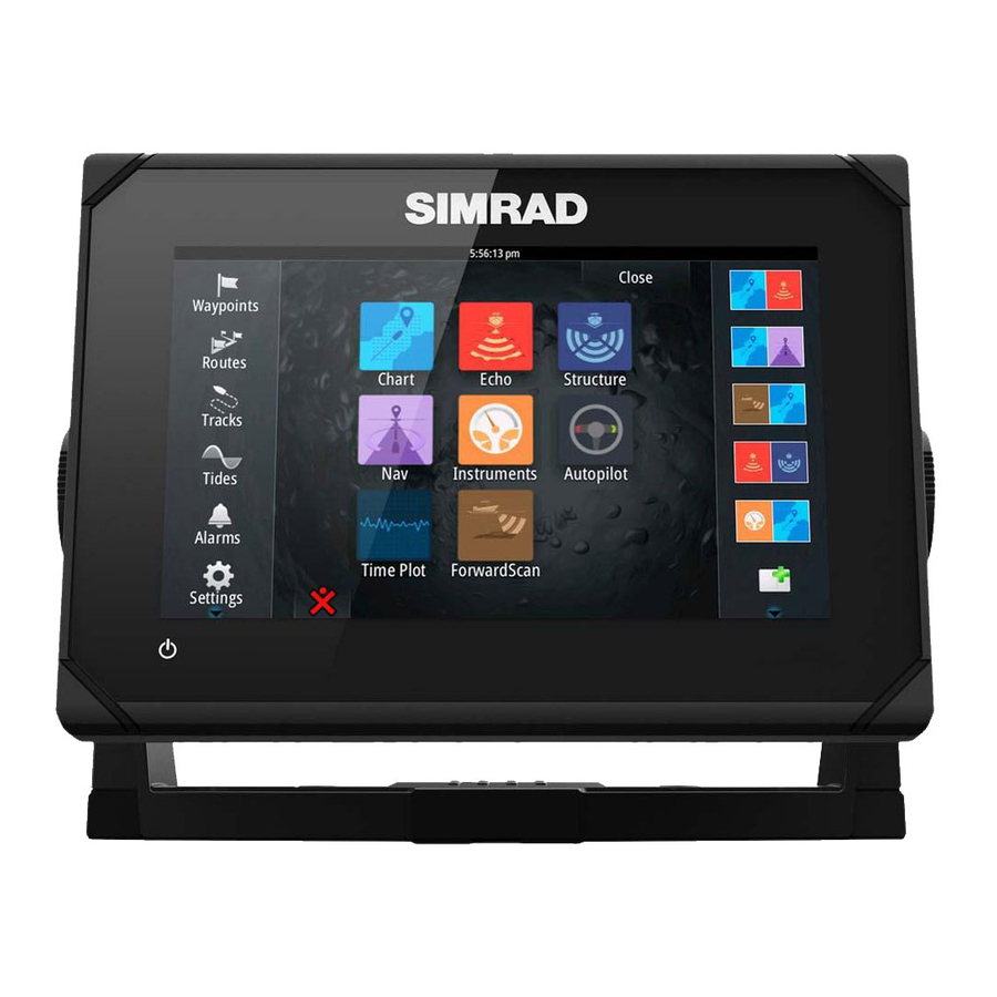
Tools panel and the icons access most settings that require configuration. First time startup When the GO7 is started for the first time, or after a factory default, the unit displays a setup wizard. Respond to the setup wizard prompts to select some fundamental setup options. - Page 23 Note: Ú In order to enable group selection, the display must be set to Simrad group. Devices with the Group set to None can be set to use different sources to those of the rest of the network devices. Software Setup...
-
Page 24: Autopilot Setup
Autopilot setup Verifying the autopilot connection When an AC12N, AC42N, or SG05 is connected to the GO7 system, the GO7 automatically detects the autopilot and an Autopilot menu icon is included in the Settings menu. If no Autopilot icon is available in the menu, establish the connection by running the auto select process. -
Page 25: Dockside Setup
Press the STBY key to ensure that the autopilot is in standby mode. Select the Commissioning option and clear the displayed dialog by pressing the STDBY key. Select your boat type. Software Setup | GO7 Installation Manual... - Page 26 (8°/sec.) for autopilot operation. The system also detects whether the drive unit is a reversible motor or if a solenoid valve is operated. Software Setup | GO7 Installation Manual...
-
Page 27: Drive Engage
Auto This option is typically used to switch between two rudder speeds on a continuous running pump, used when different rudder speeds are required for automatic and Follow-up/Non-Follow-up steering. Software Setup | GO7 Installation Manual... -
Page 28: Rudder Deadband
Transition HI/LO speed setting (the speed at which you want to change the set of steering parameters) • Automatic tuning of the steering parameters • Setting the seastate filter • Sailboat Setup menu items Software Setup | GO7 Installation Manual... -
Page 29: Compass Calibration
Ú Calibration must be made on the compass that is active for the autopilot. If the compass is not possible to initiate calibration from the device list on the GO7, refer to the compass’ own instructions regarding calibration. Note: Ú... -
Page 30: Setting Transition Speed
Active response parameter set is shown in the autopilot popup and the following abbreviations are used: HI-A High response parameters set automatically LO-A Low response parameters set automatically HI-M High response parameters set manually LO-M Low response parameter set manually Software Setup | GO7 Installation Manual... - Page 31 MANUAL Linked to the steering response control settings described previously. It may be used to manually find the optimum combination of course keeping and low rudder activity in rough but steady sea conditions. Software Setup | GO7 Installation Manual...
- Page 32 This value is used to preset the course change used when tacking in AUTO mode. When you select the left or right arrow key on the Autopilot pop-up, the course changes as much as this value. Range: 50-150 Change per step: 1 Default: 100 Units: Degrees Software Setup | GO7 Installation Manual...
-
Page 33: Transition Speed
If the value is too small it will take a long time to compensate for a heading error, and the autopilot will fail to keep a steady course. If the value is set too high the overshoot will increase and the steering will be unstable. Software Setup | GO7 Installation Manual... -
Page 34: Counter Rudder
Minimum rudder This parameter filters small rudder commands to prevent high rudder activity. Some boats may have a tendency to not respond to small rudder commands around the “course keeping” position because of a small Software Setup | GO7 Installation Manual... -
Page 35: Fuel Setup
Distance To Turn (DTT). Navigation change limit This parameter defines the maximum course change that the autopilot is allowed to make when the GO7 is following a route (NAV steering). If the required course change to the next waypoint in a route is more than the set limit, you are prompted and must acknowledge the course change before the autopilot will turn the vessel. - Page 36 Location to match the engine the device is connected to. Unconfigure - defaults the device which clears all user settings. Reset Fuel Flow - restores only the Fuel K-Value setting, if set in Calibrate. Only Navico devices can be reset. Software Setup | GO7 Installation Manual...
- Page 37 The Calibrate option is only available when Set to Ú full is selected, and a Fuel Flow is connected and set up as a source. Note: Ú A maximum of 8 engines is supported using Fuel Flow sensors. Software Setup | GO7 Installation Manual...
-
Page 38: Czone Setup
Tank data that is output by a compatible engine gateway can also be displayed, however tank configuration for such a data source is not possible from the GO7. CZone setup In order to communicate with the CZone modules connected to the network, the GO7 must be assigned a unique CZone Display Dipswitch setting. - Page 39 PC application available from BEP Marine Ltd, and associated CZone distributors. The GO7 system provides a means to load the Config file, as well as apply updates to module firmware, removing the need to take a laptop computer aboard the vessel.
-
Page 40: Wifi Setup
Connecting the tablet Navigate to the wifi network connection page on the tablet, and find the GO7, or GoFree Wifi xxxx network. If more than one is in range, review the Wireless Devices page on the GO7 to confirm which wireless device is connected to the unit. - Page 41 Device Name setting. If the GO7 does not appear, follow the on screen instructions to manually find the device. Select the graphic icon of the GO7. The GO7 displays a prompt similar to the following: Select Yes for one-time connection, or Always if device is to be remembered for regular connection.
- Page 42 The application must be installed on and run from a tablet device. The GO7 must be running Iperf server before initiating the test from the tablet. On exiting the page, Iperf automatically stops running.
-
Page 43: Software Updates And Data Backup
NMEA 2000 network devices, with files read off a memory cord inserted in the card reader. Before initiating an update to the GO7 itself, be sure to back up any potentially valuable user data. Backing up and Importing user data... -
Page 44: Software Upgrades
Importing a database Later, if the GO7 has been restored to factory defaults or user data is accidentally deleted, return to the files page, select the backed up file, and then Import. View file details for creation date. -
Page 45: Nmea 2000 Setup
NMEA 2000 setup Receive waypoint Select this option to allow another device capable of creating and exporting waypoints via NMEA 2000 to transfer directly to the GO7. Software Setup | GO7 Installation Manual... - Page 46 Send waypoint Select this option to allow another device to send waypoints via NMEA 2000. Software Setup | GO7 Installation Manual...
-
Page 47: Accessories
Part number Description 000-12366-001 GO7 Flush Mount Kit 000-12368-001 GO7 Flush Mount Sun Cover 000-12367-001 GO7 Bracket and Panel Mount Sun Cover 000-12371-001 GO7 Panel Mount Kit 000-12372-001 GO7 U Bracket 000-00128-001 Power Cable Accessories | GO7 Installation Manual... -
Page 48: Supported Data
126992 System Time 126996 Product Info 127237 Heading/Track Control 127245 Rudder 127250 Vessel Heading 127251 Rate of Turn 127257 Attitude 127258 Magnetic Variation 127488 Engine Parameters, Rapid Update 127489 Engine Parameters, Dynamic 127493 Transmission Parameters, Dynamic Supported data | GO7 Installation Manual... - Page 49 129284 Navigation Data 129539 GNSS DOPs 129540 GNSS Sats in View 129794 AIS Class A Static and Voyage Related Data 129801 AIS Addressed Safety Related Message 129802 AIS Safety Related Broadcast Message 129808 DSC Call Information Supported data | GO7 Installation Manual...
- Page 50 130842 AIS and VHF Message Transport 130843 Sonar Status – Frequency and DSP Voltage 130845 Weather and Fish Prediction and Barometric Pressure History 130850 Evinrude Engine Warnings 130851 Parameter (RC42 Compass and IS12 Wind Calibration and Configuration) Supported data | GO7 Installation Manual...
- Page 51 129284 Navigation Data 129285 Route/Waypoint Data 129539 GNSS DOPs 129540 GNSS Sats in View 130074 Route and WP Service - WP List - WP Name & Position 130306 Wind Data 130310 Environmental Parameters 130311 Environmental Parameters Supported data | GO7 Installation Manual...
- Page 52 130836 Fluid Level Insect Configuration 130837 Fuel Flow Turbine Configuration 130839 Pressure Insect Configuration 130845 Weather and Fish Prediction and Barometric Pressure History 130850 Evinrude Engine Warnings 130851 Parameter (RC42 Compass and IS12 Wind Calibration and Configuration) Supported data | GO7 Installation Manual...
-
Page 53: Specifications
36V Alarm output current 1 A max Processor iMX61 single core Conformity CE, C-Tick Interfaces NMEA 2000 (compliant) 1 port (Micro-C male) Sonar 1 port (7 pin blue connector) microSD card reader 1x microSD Specifications | GO7 Installation Manual... -
Page 54: Dimensional Drawings
Dimensional drawings Dimensional drawings | GO7 Installation Manual... - Page 56 0980...
Need help?
Do you have a question about the GO7 and is the answer not in the manual?
Questions and answers