Table of Contents
Advertisement
M A N U A L
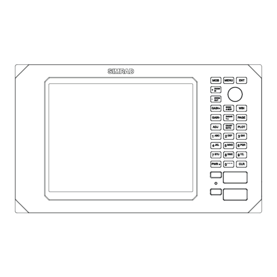
SIMRAD CA42/50/52
ChartRadar with Echosounder
183-0500-202 English
02244.30
Note!
Insert or remove C-MAP cartridges ONLY through CHART menu or when unit is off.
All electronic navigation equipment is subject to external factors beyond the control of the
manufacturer. Therefore such equipment must be regarded as an aid to navigation. The
prudent navigator will, for that reason, never rely on a single source for position fixing and
navigation.
Advertisement
Table of Contents


Need help?
Do you have a question about the CA42 and is the answer not in the manual?
Questions and answers