
Related Manuals for Simrad MX525A


Summary of Contents for Simrad MX525A
-
Page 1: Dgps Receiver
Manual Simrad MX525A DGPS Receiver English www.simrad-yachting.com A brand by Navico - Leader in Marine Electronics... - Page 2 As we are continuously improving our products we retain the right to make changes to the product and the documentation at any time. Updated manuals are available from our website www.simrad-yachting.com, and are free to download. © Copyright 2008 by Navico Holding AS.
-
Page 3: Important Notice
IMPORTANT NOTICE! THE MX525A DGPS RECEIVER IS AN AID TO NAVIGATION ONLY. Under no circumstances should it be used in lieu of authorized government charts. Its accuracy can be affected by many factors such as equipment defects, environmental conditions, or improper operation. -
Page 4: Table Of Contents
Antenna Cable Selection ......13 Power Requirement ........13 Power/Data Cable Assembly ......14 MX525A Connector Configuration ....15 Data Interface to MX420/2 or MK12 CDU ..16 Data Interface to MX420/8 or MX420/AIS CDU 17 Data Interface to MX5xx CDU ....... 18 Data Interface to PC or other navigation systems MX525A Programming Cable ...... - Page 5 Blank page 4 | Simrad MX525A...
-
Page 6: General
1 General This manual describes the operation and installation of the MX525A DGPS sensor (with the MGL-4 antenna) and older version MX525 black box DGPS sensor (with the MGL-3 antenna). Their wiring hook-up is identical and the antennas are interchangeable. -
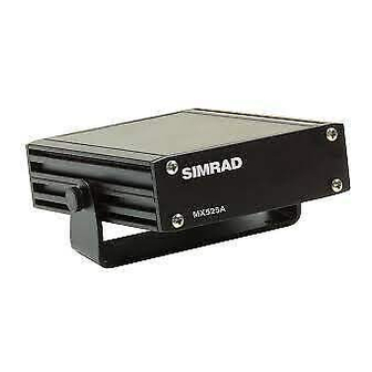
Page 7: Supplied Equipment
Supplied Equipment The following items are supplied with the MX525A DGPS Sensor Kit (p/n 9525 200 81000): Description Part Number MX525A DGPS Sensor 9525 200 81010 with mounting kit MGL-4 Combo Antenna 721757 Power/Data Cable assembly, 3 m. 3508 102 70150... -
Page 8: Operation
GPS frequency. Refer to the MX CDU Operator Manual for more details. Turning this feature ON in the MX CDU will initiate the MX525A to track any SBAS satellites that are in view. Please be aware that the SBAS system is not an IMO approved differential correction system. -
Page 9: Receiver Autonomous Integrity Monitoring (Raim)
Receiver Autonomous Integrity Monitoring (RAIM) RAIM is a special software algorithm in the MX525A program which provides another layer of safety because it gives the operator an alarm indication if the GPS system accuracy exceeds a predefined tolerance. This feature requires at least five or more GPS satellites to operate properly. -
Page 10: Installation
Locate the MX525A within 3 meters from the MX CDU junction box. Should there be a need to install the MX525A much farther away from the MX420 CDU, a longer cable assembly can be specially ordered from Simrad. - Page 11 1 through 8. The RF (TNC-F) connector is used to connect the MX525A to a combined DGPS antenna (MGL-3). Pin # Wire Wiring Comparison Color MX525A MX421B-10 Negative Ground +9 - 32 VDC MX Proprietary Message (MPM In (-)
-
Page 12: Mgl-4 Antenna Mounting Guidelines
If you are not sure if the chosen antenna location is appropriate, you can mount the MGL-4 antenna temporarily and connect the coax cable to the MX525A. Using the MX CDU, Monitor the GPS signals under the “GPS Status” screen while you move the MGL-4 antenna around. -
Page 13: Antenna Mounting
Antenna Mounting Bracket Mount The MGL-4 antenna mounting thread is an industry standard fitting for VHF antenna mounting (1.0 inch, 14 TPI). This enables the antenna to be mounted on a wide range of mounting brackets, including the swivel joints, commonly used for angled surface. -
Page 14: Antenna Cable Selection
300 mA at 12 VDC. An in-line fuse or circuit breaker rated at 2 amp. is recommended for overload protection. When the MX525A is connected to an MX CDU, the 12 VDC antenna power is supplied by the CDU unit. -
Page 15: Power/Data Cable Assembly
The red wire connects to the (+) DC power, while the black wire is the negative return. Although the MX525A has a reverse polarity protection, it is prudent to make sure that proper polarity is observed before making the connection. -
Page 16: Mx525A Connector Configuration
MX525A Connector Configuration Refer to the diagram below for the POWER-DATA connector located at the rear panel of the MX525A: POWER DATA Connector Signal Wire Pin# Ext. RTCM IN - Prpl/Gry Purple Ext. RTCM IN+ Beacon status Out + White... -
Page 17: Data Interface To Mx420/2 Or Mk12 Cdu
Data Interface to MX420/2 or MK12 Use the diagram below to interface the MX525A to an MX420/2 or MK12 CDU. MGL-4 Combo Antenna Coax Cable MX525A Console (16) Red/Wht Red (+12 VDC) (1) Blk/Shield Blk (GND) MX420/2 or (8) Org... -
Page 18: Data Interface To Mx420/8 Or Mx420/Ais Cdu
Data Interface to MX420/8 or MX420/ AIS CDU Use the diagram below to interface the MX525A to an MX420/8 or MX420/AIS CDU. The external RTCM connection is optional. MGL-4 Combo Antenna Coax Cable MX525A Console (16) Red/Wht Red (+12 VDC) -
Page 19: Data Interface To Mx5Xx Cdu
Data Interface to MX5xx CDU The standard power/data cable (P/N 3508 102 70150) for the MX525A and MX5xx CDU is pre-made with two molded 10-Pin male connectors for an easy plug-and- play connection to the back of the MX5xx CDU. If there is a need to extend (or cut) the standard cable, please refer to the diagram below for the wire splice. -
Page 20: Data Interface To Pc Or Other Navigation Systems
Blu (MPM In -) Grn (GPS Out +) Org (GPS Out -) Red (+12 VDC) Blk (GND) 1 2 3 4 5 6 7 8 9 9dB PC connector 12-32VDC Supply supplied items). MX525A Interface to other navigation systems Installation | 19... -
Page 21: Mx525A Programming Cable
Console. The diagram below shows the programming cable diagram and equipment setup. Please note that external 12 volt DC is required to power up the MX525A. Connect the red wire to +12 VDC and Black wire to negative GND. The RS422-RS232 converter may be powered from the PC serial port or from an external 12 volt power supply. -
Page 22: Specifications
4 Specifications GPS Receiver Type: ............L1, C/A Code (SPS) 1.575 GHz frequency Channels: ........12 Channels, parallel tracking (10-channel when tracking WAAS/EGNOS/MSAS) Position Update Rate: ....1 Hz (default), 5 Hz (optional) Position accuracy: With differential corrections ....<2 meters 2D-RMS depending on distance from differential base station. - Page 23 Frequency offset tolerance: ........+ 5 Hz Antenna type: ............H-Field MSK rates: ..........50, 100 and 200 bps Environmental MX525A Console Operating Temperature: ........-30 to +55 °C Storage Temperature: ........-40 to +85 °C Humidity: ....95% non-condensing, protected category MGL-3 Antenna Operating Temperature: ........
- Page 24 Mount: .............. 1 in.- 14 TPI Certifications BSH and Wheelmark IMO MSC 112(73) approved IEC 60945 ed.3, CE, and FCC compliant Simrad reserves the right to make changes in its products and specifications without notice. MGL-4 Combo Antenna 1”-14 TPI...
- Page 25 Blank page 24 | Specifications...
- Page 26 5 Data Output The MX525A data output conforms to the NMEA 0183 V3.0 at 4800 baud. Below is a list of the NMEA sentences output: NMEA 0183 V3.0: GGA, GLL, GSA, GSV, GST, RMC and NMEA 0183 Data Output Sentences (1) GGA - Global Positioning System Fix Data Time, position and fix related data for a GPS receiver.
- Page 27 Geographic Position - Latitude/Longitude (2) GLL - Latitude and Longitude of vessel position, time of position fix and status. $GPGLL,llll.llll,a,yyyyy.yyyy,a,hhmmss.ss,A,a*hh<CR><LF Notes: 1,2 ------- Latitude, N/S 3, 4 -------Longitude, E/W 5 -----------UTC of position 6 -----------Position system Mode Indicator: A=Autonomous mode D=Differential mode E=Estimated (DR) mode M=Manual input mode...
- Page 28 16 ---HDOP 17 ---VDOP (4) GSV - GPS Satellite in View Number of satellites (SV) in view, PRN numbers, elevation, azimuth and SNR values. Four satellites maximum per transmission, additional satellite data sent in second or third message. Total number of messages being transmitted and the number of the message transmitted are indicated in the first two fields.
- Page 29 3,4 -- Latitude, N/S 5,6 -- Longitude, E/W 7 ---- Speed over ground, knots 8 ---- Course Over Ground, True 9 ---- Date: dd/mm/yy 10,11 - Magnetic variation, degrees E/W. Easterly variation (E) subtracts from True course, Westerly variation (W) adds to True course.
- Page 30 6 ---- Standard deviation of latitude error (meters) 7 ---- Standard deviation of longitude error (meters) 8 ---- Standard deviation of altitude error (meters) (7) VTG - Course Over Ground and Ground Speed The actual course and speed relative to the ground. $GPVTG,x.x,T,x.x,M,x.x,N,x.x,K,a*hh<CR><LF>...
- Page 31 (9) GBS - GNSS Satellite Fault Detection (Modified MX version) This message is used to support Receiver Autonomous Integrity Monitoring (RAIM) feature in the MX420 CDU. A special character flag was added for proper RAIM status determination. $PMVXG,GBS,hhmmss.ss,x.x,x.x,x.x,xx,x.x,x.x,x.x,x*hh<CR><LF> 3 4 5 6 7 Notes: 1 ----- UTC time of the GGA or GNS fix associated with this sentence.
- Page 32 How are we doing? Please help us to help you and our other valued customers by sending us your evaluation of this manual. We need to know such things as: is the manual complete, or do you need more (or less) information? can you find the information you need easily? is the information easy to understand, or could we be...
- Page 33 Blank page 32 | Data output...
Need help?
Do you have a question about the MX525A and is the answer not in the manual?
Questions and answers