Table of Contents
Advertisement
Quick Links
Advertisement
Table of Contents
Troubleshooting

Related Manuals for Fischer Panda Panda 6000i PMS


Summary of Contents for Fischer Panda Panda 6000i PMS
-
Page 1: Panda 6000I Pms
Panda 6000i PMS Super silent technology 230V 50Hz 6kW Fischer Panda GmbH... -
Page 2: Revision
Duplication and change of the manual is permitted only in consultation with the manufacturer! Fischer Panda GmbH, 33104 Paderborn, reserves all rights regarding text and graphics. Details are given to the best of our knowledge. No liability is accepted for correctness. Technical modifications for improving the product without previous notice may be undertaken without notice. -
Page 3: Table Of Contents
Table of contents Panda 6000i PMS ........................1 Revision........................... 2 Panda 6000i system....................... 7 A.1 Components ........................7 A.2 Range of operation ......................8 A.2.1 Main features of the Panda 6000i ..................8 Panda 6000i..........................9 Part 1: Generator Manual....................... 9 Current revision status ...................... - Page 4 Table of contents C.4 The freshwater coolant circuit ..................37 C.4.1 Position of the external cooling water expansion tank ............37 C.4.2 Pressure test for controlling the cooling water circuit ............37 C.4.3 Scheme for freshwater circuit at two circuit cooling system ..........38 C.5 Water-cooled exhaust system ..................
- Page 5 Table of contents Technical data ........................ 74 F.2.1 Technical data generator ....................74 F.2.2 Technical data engine ....................... 75 Engine oil specification ....................77 Coolant specifications ....................78 Panda i-series ........................79 Part 2: Panel Panda iControl Manual.................. 79 Current revision status ......................80 Panda iControl ......................
- Page 6 Table of contents A.5.2 Load at the PMGi ....................... 99 A.5.3 Automatic start ........................99 A.6 Status LED´s ........................99 A.7 Cooling of the PMGi ..................... 100 A.8 Installation of the PMGi ....................100 A.8.1 Electrical connection......................100 A.8.2 Installation of the ferrites ....................
-
Page 7: Panda 6000I System
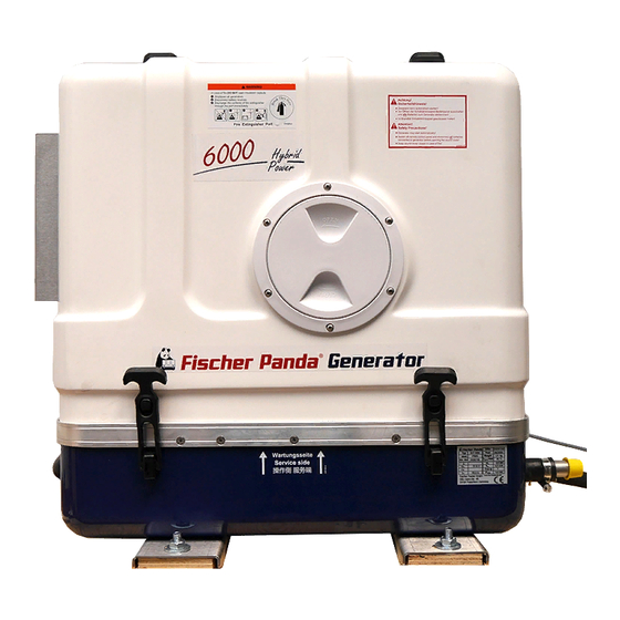
Panda 6000i system A. Panda 6000i system A.1 Components 1. Panda 6000i PMS Generator Permanent-Magnet-Generator Art. no. C10060BX1SV01 Manual see “Part 1: Generator Manual” on page 9. Fig. A.1-1: Panda 6000i generator 2. Panel Panda iControl with electronic board at the generator Art no. -
Page 8: Range Of Operation
Panda 6000i system A.2 Range of operation Reliable power supply on sailing boats. A.2.1 Main features of the Panda 6000i • Extremely high starting capacity, perfect for a Bauer junior II compressor or air conditioner! • 230V / 50Hz system for all your domestic appliances! •... -
Page 9: Panda 6000I
Panda 6000i Part 1: Generator Manual Panda 6000i PMS 230V/50Hz 6kW Fischer Panda GmbH... -
Page 10: Current Revision Status
Current revision status Document Actual: Panda 6000i generator_s01835_eng.R01_16.1.09 Replace: Revision Page... - Page 11 3500 kW from the main machine) Fischer Panda GmbH, 33104 Paderborn, reserves all rights regarding text and graphics. Details are given to the best of our knowledge. No liability is accepted for correctness. Technical modifications for improving the product without previous notice may be undertaken without notice. Before installation, it must be ensured that the...
-
Page 12: Safety First
Safety first These symbols are used throughout this manual and on labels on the maschine itself to warn of the possibility of personal injutry. Read these instructions carefully. It is essential that you read the instructions and safety regulations before you attempt to assemble or use unit. This danger symbol refers to toxic danger and draws attention to special warnings, instructions or procedures which, if not strictly observed, may result in severe personal injury or loss of life. -
Page 13: Tools
Tools This symbols are used throughout this manual to show which tool must be used at maintenance or installation. Spanners X = number of spanner Hook wrench for oil filter Screw driver, for slotted head screws and for recessed head screws Multimeter, multimeter with capacitor measuring Infrared temperature mesuring pistol Current clamp (DC for synchron generators;... - Page 14 Socket wrench set Hexagon wrench keys...
-
Page 15: Safety Precautions
You receive free upgrades, if necessary Further advantages: With your full information, the Fischer Panda technicians can give you fast assistance, since 90 % of the distur- bances result from errors in the periphery. Problems according to errors in the installation can be recognized in advance. - Page 16 The electrical Installations may only be carried out by trained and examined personnel! The generator may not be taken into use with the cover removed. The rotating parts (belt-pulley, belts, etc) must be covered and protected so that there is no danger to life and body! If a sound insulation cover must be produced at the place of installation, then well-placed signs must show that the generator can only be switched on with a closed capsule.
- Page 17 Safety Instrictions for handling batteries These instructions must be noticed additionally to the instructions of the battery manufacturer: • If the batteries are working, someone should be in your near area to help you in a case of emergency. • Water and soap must be hold ready if battery acid corrode your skin.
- Page 18 Intentionally Blank...
-
Page 19: Panda 6000I Pms Generator
Panda 6000i PMS generator B. Panda 6000i PMS generator B.1 Type plate at the generator Fig. B.1-1: Type plate Fig. B.1-2: Discription type plate 16.1.09 Panda 6000i generator_s01835_eng.R01 - Chapter: B: Panda 6000i PMS generator Page 19... -
Page 20: Right Side View
06) Sound cover base part 14) Ventilation pipe to external expansion tank 07) Heat exchanger 15) Watercooled exhaust elbow 08) Starter motor Fig. B.2.1-1: Right side view Page 20 Panda 6000i generator_s01835_eng.R01 - Chapter: B: Panda 6000i PMS generator 16.1.09... -
Page 21: Left Side View
13) Thermoswitch cylinder head 06) Oil dipstick 14) Air suction housing 07) Raw water intake 15) Charge controller for DC-alternator 08) Raw water intake pipe Fig. B.2.2-1: Left side view 16.1.09 Panda 6000i generator_s01835_eng.R01 - Chapter: B: Panda 6000i PMS generator Page 21... -
Page 22: Front View
22) Ventilation screw internal cooling water pump 11) Cable for iControl panel 23) Pulley for internal cooling water pump 12) Passage for starter battery cable (-) Fig. B.2.3-1: Front view Page 22 Panda 6000i generator_s01835_eng.R01 - Chapter: B: Panda 6000i PMS generator 16.1.09... -
Page 23: Back View
06) Connection from external expansion tank 13) Ventilation pipe to external expansion tank 07) Connection to external expansion tank 14) Watercooled exhaust elbow Fig. B.2.4-1: Back view 16.1.09 Panda 6000i generator_s01835_eng.R01 - Chapter: B: Panda 6000i PMS generator Page 23... -
Page 24: View From Above
20) Actuator 10) Exhaust outlet 21) Fuel solenoid valve 11) Connection for external ventilation valve 22) Ventilation screw internal cooling water pump Fig. B.2.5-1: View from above Page 24 Panda 6000i generator_s01835_eng.R01 - Chapter: B: Panda 6000i PMS generator 16.1.09... -
Page 25: Details Of Function Units
B.3.1 Remote control panel - See Panda iControl manual B.3.2 Components of the cooling system (raw- and freshwater) Fig. B.3.2-1: Cooling system 16.1.09 Panda 6000i generator_s01835_eng.R01 - Chapter: B: Panda 6000i PMS generator - Description of the generator Page 25... -
Page 26: Components Of The Fuel, Air Intake And Exhaust System
Panda 6000i PMS generator B.3.3 Components of the fuel, air intake and exhaust system Fig. B.3.3-1: Fuel, air intake and exhaust system Page 26 Panda 6000i generator_s01835_eng.R01 - Chapter: B: Panda 6000i PMS generator - Description of the generator 16.1.09... -
Page 27: Components Of The Electrical System
Panda 6000i PMS generator B.3.4 Components of the electrical system Fig. B.3.4-1: Electrical system 16.1.09 Panda 6000i generator_s01835_eng.R01 - Chapter: B: Panda 6000i PMS generator - Description of the generator Page 27... -
Page 28: Components Of The Lubrication System
Panda 6000i PMS generator B.3.5 Components of the lubrication system Fig. B.3.5-1: Lubrication system Page 28 Panda 6000i generator_s01835_eng.R01 - Chapter: B: Panda 6000i PMS generator - Description of the generator 16.1.09... -
Page 29: Sensors And Switches For Operating Surveillance
Fig. B.3.6-2: Thermo-sensor at exhaust connection Thermo-switch coil One thermo sensor is located in the stator winding Fig. B.3.6-3: Thermo-switch coil 16.1.09 Panda 6000i generator_s01835_eng.R01 - Chapter: B: Panda 6000i PMS generator - Description of the generator Page 29... -
Page 30: Operation Instructions - See Panda Icontrol Panel Manual
B.4.1 Daily routine checks before starting - See Panda iControl manual B.4.2 Starting generator - See Panda iControl manual B.4.3 Stopping the generator - See Panda iControl manual Page 30 Panda 6000i generator_s01835_eng.R01 - Chapter: B: Panda 6000i PMS generator - Description of the generator 16.1.09... -
Page 31: Installation Instructions
Installation Instructions C. Installation Instructions C.1 Placement Since Panda generators have extremely compact dimensions, they can be installed in tight locati- ons. Attempts are sometimes made to install them in almost inaccessible places. Please consider that even almost maintenance-free machinery must still remain accessible at least at the front (drive belt, water pump) and the service-side (actuator, dipstick). -
Page 32: Generator Connections
Installation Instructions C.2 Generator connections Connect all electrical wires within the capsule tightly to the motor and the generator. This is also the case for fuel lines and cooling water lines. The electrical connections MUST be carried out according to the respective valid regulati- ons. -
Page 33: Cooling System Installation - Raw Water
Installation Instructions C.3 Cooling system installation - Raw water C.3.1 General information The genset should have its own raw water (coolant water) inlet and should not be connected to any other engine systems. Ensure that the following installation instructions are complied with: For the avoidance of galvanic corrosion, refer to the chapter "Service instruction for marine generators (corrosion protection)". -
Page 34: Generator Installation Above Waterline
A repair is then very expensive. Replacement impeller and also a spare pump should always be on board. The old pump can be sent back to Fischer Panda. 1. Raw water filter 2. Water cock 3. -
Page 35: Generator Installation Below Waterline
Installation Instructions C.3.5 Generator installation below waterline If the generator cannot be attached at least 600 mm above the waterline, a vent valve must be installed at the raw water line. Possible heeling must be taken into consideration if installed at the "mid-ship line"! The water hose for the external vent valve is located at the back of the sound insulated cover. -
Page 36: Indirect Cooling Of The Genset Housing (By The Heat Exchanger)
Installation Instructions C.3.6 Indirect cooling of the genset housing (by the heat exchanger) 1. Ventilation valve 5. Raw water filter 2. Exhaust elbow 6. Water cock 3. Raw water pump (Raw water impeller pump) 7. Hull inlet 4. Heat exchanger Fig. -
Page 37: The Freshwater Coolant Circuit
Installation Instructions C.4 The freshwater coolant circuit C.4.1 Position of the external cooling water expansion tank Position of the external cooling water expansion tank The Panda generator is normally supp- lied with an additional, external cooling water expansion tank. This tank must be installed in such a way that its lower edge is at least 500 mm more highly arranged than the upper edge of the... -
Page 38: Scheme For Freshwater Circuit At Two Circuit Cooling System
Installation Instructions C.4.3 Scheme for freshwater circuit at two circuit cooling system 1. Expansion Tank 4. Freshwater pump 2. Exhaust Manifold 5. Heat Exchanger 3. Thermostat Housing 6. Engine Fig. C.4.3-1: Scheme for freshwater circuit at two circuit cooling system Page 38 Panda_6000i_System_eng_s01835.book.R01 - Chapter C: Installation Instructions 16.1.09... -
Page 39: Water-Cooled Exhaust System
Installation Instructions C.5 Water-cooled exhaust system By injecting the outlet raw water into the exhaust manifold, the exhaust gases are cooled and the noise emissions from the exhaust system are reduced. C.5.1 Installation of the standard exhaust system The generator exhaust system must remain completely independent and separate from the exhaust system of any other unit(s) on board. -
Page 40: Exhaust / Water Separator
Installation Instructions C.5.2 Exhaust / water separator In order to reduce the noise level of the generator unit to a minimum, an optional exhaust outlet muffler can be mounted next to the thru-hull fitting. Additionally there is a component at Fischer Panda, which acts as both an "exhaust goose neck", and water separator. -
Page 41: Installation Exhaust-Water-Separator
Installation Instructions C.5.3 Installation exhaust-water-separator If the exhaust/water separator was sufficiently highly installed, a goose neck is no longer neces- sary. The exhaust/water separator fulfils the same function. If the "Super silent" exhaust system were installed correctly, the generator will not disturb your boat neighbour. The exhaust noise should be nearly inaudible. - Page 42 Installation Instructions Example of an unfavourable installation: - Water lock not far enough below the highest level of the generator - Distance water lock to exhaust/water separator too large Fig. C.5.3-2: Expample for an unfavourable installation Page 42 Panda_6000i_System_eng_s01835.book.R01 - Chapter C: Installation Instructions 16.1.09...
-
Page 43: Installation Of The Fuel System
Installation Instructions C.6 Installation of the fuel system C.6.1 General references Inside the generator capsule itself, there is the fuel filter installed (exception: Panda 4200 and 4500). Additional fuel filters (with water separator) must be mounted outside the capsule in easily accessible places in the fuel lines between the tank intake fuel pump and the diesel motor's fuel pump. -
Page 44: The Electrical Fuel Pump
Installation Instructions C.6.2 The electrical fuel pump Electrical Fuel Pump With the Panda generator is usually supp- lied an external, electrical fuel pump (12 V DC). The fuel pump must be installed close at the fuel tank. The electrical con- nections are pre-loaded at the generator with the lead planned. -
Page 45: Position Of The Pre-Filter With Water Separator
Installation Instructions C.6.4 Position of the pre-filter with water separator Additionally to the standard fine filter a pre-filter with water separator must be installed outside of the sound insulation capsule in the fuel system line (not inclu- ded in the delivery). Fig. -
Page 46: Generator 12Vdc System Installation
Installation Instructions C.7 Generator 12VDC system installation The Panda generators have their own dynamo to charge a 12V starter battery. It is recommended to install an additional starter battery for the generator. The generator is then independent from the remaining battery set. This enables you to start the genset at any time with its own starter battery even if the other batteries are discharged. - Page 47 Installation Instructions C.8 Generator AC system installation ATTENTION! Before the electrical system is installed, READ the SAFETY INSTRUCTIONS of this manual FIRST! Be sure that all electrical installations (including all safety systems) comply with all required regulations of the regio- nal authorities.
-
Page 48: Installation Pmgi Inverter - See Separat Pmgi 6000 Inverter Manual
Installation Instructions C.8.1 Installation PMGi inverter - See separat PMGi 6000 inverter manual Page 48 Panda_6000i_System_eng_s01835.book.R01 - Chapter C: Installation Instructions 16.1.09... -
Page 49: Generator Failure
Generator Failure D. Generator Failure ATTENTION! Before working on the System read the section , “Safety Precautions,” on page 15. D.1 Tools and measuring instruments In order to be able to manage disturbances while driving, following tools and measuring instruments should belong to the equipment on board: •... -
Page 50: Low Generator-Output Voltage
Generator Failure D.2.1 Low generator-output voltage ATTENTION! Before working on the System read the section “Safety Precautions” on Page 15. If the produced alternating voltage is too low, switch the load off, in order to relieve the generator. Mostly the problem already solved. If the output voltage is still too low, even if all load is switched off, the generator runs without load, you can assume one or more condensers are defective. -
Page 51: Dirty Fuel Filter
Generator Failure D.3.2 Dirty fuel filter If the fuel filter is dirty change the filter ele- ment. For replacing the filter element see section C.3.1, “Replacing fuel filter” on page 79. 1. Fuel filter element Fig. D.3.2-1: Fuel filter D.4 Troubleshooting table For troubleshooting see section F.1, “Troubleshooting”... - Page 52 Generator Failure Intentionally Blank Page 52 Panda 6000i generator_s01835_eng.R01 - Chapter D: Generator Failure 16.1.09...
-
Page 53: Maintenance Instructions
Maintenance Instructions E. Maintenance Instructions ATTENTION! Before working on the System read the section , “Safety Precautions,” on Page 15. E.1 General maintenance instructions E.1.1 Checks before starting • Oil level • Cooling system leaks • Visual check for any changes, leaks oil drain system, v-belt, cable connections, hose clips, air filter, fuel lines Once a month •... -
Page 54: Execution Of An Oil Change
Maintenance Instructions E.2.1 Execution of an oil change Oil drain hose For the oil change an oil drain hose is fed through the sound insulation capsule. Fig. E.2.1-1: Oil drain hose Oil Drain Screw The oil can be discharged by opening the oil drain screw. - Page 55 Maintenance Instructions Oil Filter Change The oil filter can be loosened by means of an oil filter strap. Fig. E.2.1-4: Oil filter change Oil filter gasket The gasket should be coated with oil before inserting the new oil filter. Tighten the oil filter by hand only. Fig.
- Page 56 Maintenance Instructions Oil Dipstick The oil level is checked by use of the engine oil dipstick. The prescribed filling level may not exceed the "Max"marking. Fig. E.2.1-7: Oil dipstick Page 56 Panda_6000i_System_eng_s01835.book.R01 - Chapter E: Maintenance Instructions 16.1.09...
-
Page 57: Ventilating The Fuel System
Maintenance Instructions E.3 Ventilating the fuel system Normally, the fuel system is designed to ventilate air itself i.e. as soon as the electric starter motor starts operation the fuel pump starts working and the fuel system will be de-aerated after some time automatically. -
Page 58: Replace Of The Fuel Filter
Maintenance Instructions 4. Open the ventilation screw located at the fuel solenoid valve. The „START“ button must continue to be pressed, whilst opening the screw. A large cloth or Kleenex tissue must be laid beneath the connection to prevent escaping fuel running into the capsule. -
Page 59: Checking The Water Separator In The Fuel Supply
Maintenance Instructions E.3.2 Checking the water separator in the fuel supply The pre-filter with water separator has a cock underneath, by which means the water can be drained. This water sinks to the bottom, due to its density. It is heavier than the diesel Fig. -
Page 60: Replace The Air Filter Mat
Maintenance Instructions E.4 Replace the air filter mat 1. Open the air suction housing by loosen the six screws on the housing cover. Fig. E.4-1: Air suction housing 2. Change the air filter mat. 3. Close the suction air housing. Fig. -
Page 61: Ventilation Of The Coolant Circuit / Freshwater
Maintenance Instructions E.5 Ventilation of the Coolant Circuit / Freshwater Special notes for the ventilation of the cooling system If the cooling water is drained, or if other air has entered the cooling system, it is necessary to ventilate the cooling system. This ventilating procedure must be repeated several times: ATTENTION! The generator must be switched off before... - Page 62 Maintenance Instructions 2. Open the ventilating screw on the ther- mostat casing. Fig. E.5-3: Ventilating screw on the thermostat housing 3. Now the cooling water is only filled over the external expansion tank. This is connected by 2 hoses with the genset. The external expansion tank should be filled in the cold condition only up to maximally 20%.
-
Page 63: Replace Of The V-Belt For The Internal Cooling Water Pump
Maintenance Instructions E.6 Replace of the v-belt for the internal cooling water pump The relative high ambient temperature in the closed sound insulated capsule (about 85° C) can be a reason for a reduced lifespan of the v-belts. It is possible that the "softener" in the rubber com- pound lose their effect after a short operating time because the air in the sound insulated capsule can be relative warm and dry. - Page 64 Maintenance Instructions 3. Press the alternator in the direction of the thermostat casing. 4. Replace the v-belt. Fig. E.6-3: DC alternator 5. Re-tighten V-belt The v-belt should only be tightened to the extent that it can be pushed to the length of a thumb (approx.
-
Page 65: The Raw Water Circuit
Maintenance Instructions E.7 The Raw water circuit E.7.1 Clean raw water filter Residue should be regularly removed from the seawater filter. The seacock must, in each case, be closed first. It often suffices to merely hit the filter punnet. If water should seep through the cover of the raw water filter, this may never be sea- led with adhesive or sealant. -
Page 66: Replace The Impeller
Maintenance Instructions E.7.3 Replace the impeller 1. Close the raw water valve. Fig. E.7.3-1: Raw water valve 2. The raw water pump is located on the front side of the genset. Fig. E.7.3-2: Raw water pump 3. Remove the cover of the raw water pump by loosen the screws from the housing. - Page 67 Maintenance Instructions 4. Remove the impeller from the shaft by means of multi grip pliers.. 5. Mark the impeller, to make sure that it is in the correct position when re-instal- lation is carried out. Fig. E.7.3-4: Impeller 6. Check the impeller for damage and replace it if necessary.
-
Page 68: Conservation Of The Generator (Long Operation Interruption)
Maintenance Instructions E.8 Conservation of the generator (long operation interruption) E.8.1 Measures for preparation of winter storage 1. Rinse seawater circuit with an anti-freeze solution, if this contains a corrosion protection solu- tion. The seawater intake must be stopped at the seacock. The anti-freeze protection mixture is to be sucked up from a container by means of a hose connection. -
Page 69: Initiation During Spring
Start generator and check the basic adjustments of the generator such as voltage, speed re- gulation etc... • Check all switching off devices for function by operational procedures. Fischer Panda does not take over adhesion for possible damages! 16.1.09 Panda_6000i_System_eng_s01835.book.R01 - Chapter E: Maintenance Instructions Page 69... - Page 70 Maintenance Instructions Intentionally Blank Page 70 Panda_6000i_System_eng_s01835.book.R01 - Chapter E: Maintenance Instructions 16.1.09...
-
Page 71: F Tables
Tables F. Tables Troubleshooting GENERATOR OUTPUT VOLTAGE TOO LOW If the generator delivers less than 24V current ("undervoltage"), there can be various reasons for this: Cause Solution PGMi is overloaded. Reduce the electrical load. (Switch off load) Motor is not reaching the rated rpm. Refer to "motor faults"... - Page 72 Tables MOTOR DOES NOT TURN OVER AT THE NORMAL SPEED DURING THE STARTING PROCESS Cause Solution Starter battery voltage insufficient. Check battery. Damaged bearing(s) piston (seized). Repairs need to be carried out by Kubota-Service. (refer to Kubota motor-manual) Cooling water in combustion chamber. 1.
- Page 73 Tables MOTOR SWITCHES ITSELF OFF Cause Solution Fuel solenoid valve or throttle shut solenoid is not swit- Check wire connections to solenoid. Check valve ching off. functions as in the "Inlet Fuel Solenoid Valve" or in the trottle shut off solenoid sections. Replace if necessary. MOTOR STOPS BY ITSELF Cause Solution...
-
Page 74: Technical Data
- exhaust colour suddenly becomes dark - motor overheats - oil pressure drops, oil light suddenly flashes Technical data F.2.1 Technical data generator Generator Panda 6000i PMS Generator type PM-Synchronous Generator Winding type Wiring mode Protection mode IP 44... -
Page 75: Technical Data Engine
Tables F.2.2 Technical data engine Model Kubota Z 482 Type Vertical, water-cooled, 4-cycle diesel engine No. cylinders Bore [mm] Stroke [mm] Total displacement [ccm] Combustion chamber Spherical type (E-TVCS) SAE NET intermittent (SAE J1349) at 3600rpm [kW] SAE NET continuous (SAE J1349) at 3600rpm [kW] Maximum bare speed [rpm] 3800 Minumum bare idling speed [rpm]... - Page 76 Supply Return Generatortype [mm] [mm] [mm] [mm] [mm] Panda 6000i PMS Table 3: Diameter of conduits Wiring for vehicles. single phase, not tin-plated, PVC-isolated. allowed continous current (reference point) nominal wire cross-section [mm²] at +30° C [A] at +50° C [A]...
-
Page 77: Engine Oil Specification
Tables Engine oil specification Engine oil classification Operating range: The operating range of an engine oil is determined by SAE class. "SAE" is for the union of American engineers (Society of Automotives Engineers). The SAE class of an engine oil only informs over the viscosity of the oil (lar- ger number = more viscous, lower number = more highly liquidly) e.g. -
Page 78: Coolant Specifications
Use a mixture of water and antifreeze. The antifreeze needs to be suitable for aluminium. The antifreeze concen- tration must be regularly checked in the interests of safety. Fischer Panda recommend to use the product: GLYSANTIN PROTECT PLUS/G 48 Engine coolant automotive industry Product description Product name GLYSANTIN ®... -
Page 79: Panda I-Series
Panda i-series Part 2: Panel Panda iControl Manual Panel Panda iControl Fischer Panda GmbH... -
Page 80: Current Revision Status
Current revision status Document Actual: Panda_iControl_eng.R03_16.1.09 Replace: Panda_iControl_eng.R02 Revision Page Update the whole manual connection to 6000i update... -
Page 81: Panda Icontrol
Panda iControl Fischer Panda Datasheet A. Panda iControl Art Nr. 21.02.02.01H Bez. Panda iControl Document Hardware Software Actual: Replace: Panel_iControl_eng.fm Chapter A: Panda iControl Page 81... -
Page 82: Safety Instructions
Panda iControl Fischer Panda Datasheet A.1 Safety instructions The generator may not be taken into use with the cover removed. The rotating parts (belt-pulley, belts, etc) must be covered and protected so that there is no danger to life and... -
Page 83: Buttons And Display Of The Icontrol
Panda iControl Fischer Panda Datasheet Note Regarding to the open electric board the iControl panel has a protectrive class IP00. Builded in a control board with a siutable seal (f.e. Sikaflex) IP66 can be reached. A.3 Buttons and display of the iControl Button „on/off“... -
Page 84: Engine Control
Panda iControl Fischer Panda Datasheet A.4 Engine control The iControl Panel and Electronic Board is for driving the Panda i-series generator. Push the „on/off“ button to start the panel(1). The panel will come up in the „stand by mode“. „stand by mode“... -
Page 85: General
Tips regarding Starter Battery Fischer Panda recommends the use of a normal starter battery. If a genset is required for extreme winter conditi- ons, then the starter battery capacity should be doubled. It is recommended to charge the starter battery regularly by a suitable battery-charging device (i.e., at least every 2 months). -
Page 86: Long Time Run Of The Generator
Panda iControl Fischer Panda Datasheet Engine Oil at winter conditions. Make sure using a siutable engine oil at winter conditions. Do not use start help sprays or similar. A.5.3 Long time run of the generator Make sure the PMGi is not overloaded. The PMGi will switch off in this case. -
Page 87: Stop Of The Generator
Panda iControl Fischer Panda Datasheet A.5.5 Stop of the generator 1. At higher temperatures (over 25° C) the generator should run 5 min. after the load has been switched off in order to cool down) 2. Push the „start/stop“ button to switch off the generator. -
Page 88: Error Warnings
Panda iControl Fischer Panda Datasheet A.6 Error warnings Error warnings are shown in the display. The screen switch from the temperature to „High“. Following warnigs are displayed Engine temp. > 75 °C Exhaust temp. > 70 °C Winding temp. > 120 °C... -
Page 89: Electronic Board
Panda iControl Fischer Panda Datasheet Example for an error display after the generator was stopped. (Oil Pressure failed) Fig. A.7-1: Display warning (oil pressure failed) - example A.8 Electronic board The iControl panel has an electronic board which is mounted at the Generator. This board controls all generator functions. -
Page 90: Technical Data
Panda iControl Fischer Panda Datasheet A.9 Technical data A.9.1 Intended use The Panda iControl is a part of the Panda i-series generator. It is not allowed to use the iControl at other genera- tors or applications. The iControl must be connected with the electronic board at the generator. -
Page 91: Dimensions
Panda iControl A.9.2 Dimensions Fig. A.9.2-1: Dimensions Panel_iControl_eng.fm Chapter A: Panda iControl Page 91... - Page 92 Panda iControl Intentionally Blank Page 92 Chapter A: Panda iControl Panel_iControl_eng.fm...
-
Page 93: Panda I-Series
Panda i-series Part 3: PMGi 6000 inverter Manual PMGi 6000 Fischer Panda GmbH... -
Page 94: Current Revision Status
Current revision status Document Actual: Panda_PMGi_6000_eng.R01_16.1.09 Replace: Revision Page... -
Page 95: Panda Pmgi 6000
Panda PMGi 6000 Fischer Panda Datasheet A. Panda PMGi 6000 Art Nr. 21.07.03.008P Bez. Panda PMGi 6000 Document Hardware Software Actual: Replace: PGMi 6000_eng.fm Chapter A: Panda PMGi 6000 Page 95... -
Page 96: Safety Instruction
Panda PMGi 6000 Fischer Panda Datasheet A.1 Safety instruction The generator may not be taken into use with the cover removed. The rotating parts (belt-pulley, belts, etc) must be covered and protected so that there is no danger to life and... -
Page 97: Front Side/Connection Side
Panda PMGi 6000 Fischer Panda Datasheet A.3 Front side/connection side To connect the PMGi 6000 use the prepared cable with t he 4pin plug and connect to socket 3 (PMGi in-450V/ 400Hz) Connect your termination box with the socket 1. Use a... -
Page 98: Back Side - Top Side
Panda PMGi 6000 Fischer Panda Datasheet A.4 Back side - Top side Inside of the PMGi a fan is mounted. The air holes and air grille should not be covered. 01. Air holes Fig. A.4-1: Back side Attention! Inside of the PMGi are up to 550VAC. The cover of the PMGi should only be opened by special trained persons !!! Danger for Live“... -
Page 99: Operation Manual
Panda PMGi 6000 Fischer Panda Datasheet A.5 Operation manual A.5.1 Primary remarks / Winter operation The PGMi can operate in the range of -20°C to +40° C . A.5.2 Load at the PMGi Do not overload the PMGi. It will go on error. -
Page 100: Cooling Of The Pmgi
Panda PMGi 6000 Fischer Panda Datasheet A.7 Cooling of the PMGi Inside of the PMGi a fan is mounted. Do not cover the air holes and grille. The heat sink and the fan of the PMHGi may become dirty as a consequence of tzhe use of the generator, and so the unit can loose a part of their heat transfer carateristic. -
Page 101: Installation Of The Ferrites
Panda PMGi 6000 Fischer Panda Datasheet A.8.2 Installation of the ferrites Ferrit to clip on the cable Fig. A.8.2-1: Installation of the ferrites Ferrit to clip on the cable cip the ferrit on thr cable which is going from the PMGi to your electrical cabinet. -
Page 102: Technical Data
Panda PMGi 6000 Fischer Panda Datasheet Ferritring Insert the cable comming from the generator about 10cm through the ring. Turn it back and insert it through again. (second time) Turn it back and insert it through again. (Third time) The ferrit should be as close to the PMGi as possible. -
Page 103: Pmgi Out
Panda PMGi 6000 Fischer Panda Datasheet A.9.3 PMGi out Voltage Nominal Voltage 230V VAC +/- 5% without load Regulation Stability (short term (30sec)) Stability (Long term (4h)) Voltage offset +-5V -20° C bis +40°C offset Current Current @230V 26 A Nominal eff. -
Page 104: Pmgi Protections
Panda PMGi 6000 Fischer Panda Datasheet A.10 PMGi protections A.10.1Overload - switch point Output type Max. current Comments 230VAC 30,0A +/- 0.5A When protection takes place the engine must be swit- ched off and all apliances detached Table 5: Overload A.10.2Short circiut... -
Page 105: A.10.4Overheat
Panda PMGi 6000 Fischer Panda Datasheet A.10.4Overheat Output type Max. temperature at Comments cooling plate 60° C +/- 5°C When protection takes place the engin e must be swit- ched off. Detach all the appliances and wait for cooling down of the PGMi... - Page 106 Panda PMGi 6000 Fischer Panda Datasheet Intentionally Blank Page 106 Chapter A: Panda PMGi 6000 PGMi 6000_eng.fm...
Need help?
Do you have a question about the Panda 6000i PMS and is the answer not in the manual?
Questions and answers