Table of Contents
Advertisement
Quick Links
Advertisement
Table of Contents

Related Manuals for Sper scientific 800023


Summary of Contents for Sper scientific 800023
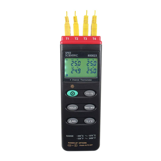
- Page 1 4-Channel Thermometer 800023 INSTRUCTION MANUAL SPER SCIENTIFIC LTD.
-
Page 2: Table Of Contents
THERMOMETER CONTENTS TITLE PAGE I. Introduction……………………………….…………..…….….. 1 II. Specifications………………………………..………………... 1 III. Symbol Definition and Button Location………………….… 3 IV. Operation Instructions………………………...……………...5 4.1 Power-Up & turn ON/OFF backlight…………...……….. 5 4.2 Connection the Thermocouples…………..……….……..5 4.3 Selecting the Temperature Scale………………………...5 4.4 Data-Hold Operation………………………….…………...5 4.5 T1-T2 Operation…………………………………………... 5 4.6 Relative Operation…………………………………………6 4.7 MAX/MIN Operation…………………………………….…... -
Page 3: Introduction
THERMOMETER Standards and IEC584 temperature/voltage table for K-type thermocouples. It uses RS232 interface to perform bi-directional communication with PC. II. Specifications: Numerical Display: 4 digital Liquid Crystal Display per channel. Measurement Range: -200°C ~ 1370°C -328°F ~ 2498°F Resolution: -200°C~ 200°C 0.1°C; 200°C ~1370°C 1°C -200°F~ 200°F 0.1°F;... - Page 4 THERMOMETER add the following tolerance into the accuracy spec. 0.01% of reading + 0.03°C ( 0.01% of reading + 0.06°F ) Note: The basic accuracy Specification does not include the error of the probe. Please refer to the probe accuracy specification for additional details. Electromagnetic Compatibility: Total accuracy=specified accuracy ±...
-
Page 5: Symbol Definition And Button Location
THERMOMETER III. Symbol Definition and Button Location: : This indicates that the minus temperature is sensed. ℃℉ : Centigrade and Fahrenheit indication. : Thermocouple Type Indication. : The Maximum value is now being displayed. : The Minimum value is now being displayed. : This indicates auto power off is enabled. - Page 6 THERMOMETER T1-T2 HOLD 9V BATTERY NEDA 1604 6F22 006P PLEASE READ MANUAL FOR SAFETY RANGE 200 C 1370 C 2498 OPEN POWER-UP OPTIONS Button Location: K type temperature sensor T1 to T4 input connector ○ LCD display ON/OFF & Backlight button ○...
-
Page 7: Operation Instructions
THERMOMETER IV. Operation Instructions: 4.1 Power-Up & Turn ON/OFF backlight The ○ key turns the Thermometer ON or OFF and backlight ON & OFF. Press it once to turn on the Thermometer. Press it again for moment to turn ON or OFF backlight. Press and hold this button 3 second to turn OFF the power. -
Page 8: Relative Operation
THERMOMETER minus T2 mode. The temperature difference is shown on the right hand side display as shown in Fig. 4.6 Relative Operation: When pressing the “△REL” button, the meter will memorize the present reading and the difference between the new reading and the memorized data will be shown on the display. -
Page 9: Auto Power Off
THERMOMETER “ °C/°F ” ,“△REL” button in "MAX MIN" mode, there will be two continuous beep) To exit the MAX/MIN mode, one may press and hold "MAX MIN" for two seconds. 4.8 Auto Power Off: By default, when the meter is powered on, it is under auto power off mode. -
Page 10: Appendix: Thermocouple Probe Specification
THERMOMETER Appendix: Thermocouple probe specification Description Range Tolerances -50℃ to 200℃ ±2.2℃ or ±0.75% with Teflon tape insulation -58℉ to 392℉ (±3.6℉ or ±0.75%) Maximum insulating temperature : 260℃...
Need help?
Do you have a question about the 800023 and is the answer not in the manual?
Questions and answers