
Related Manuals for Kontron KT965/ATXE


Summary of Contents for Kontron KT965/ATXE
-
Page 1: User Manual
KT965 Family KTD-00699-S Public User Manual Date: 2010-04-15 Page 1 of 90 User Manual for the Motherboards: KT965/Flex KT965/ATXP KT965/ATXE... -
Page 2: Document Revision History
Brand and product names are trademarks or registered trademarks of their respective owners. Disclaimer: KONTRON Technology A/S reserves the right to make changes, without notice, to any product, including circuits and/or software described or contained in this manual in order to improve design and/or performance. -
Page 3: Life Support Policy
KONTRON Technology Technical Support and Services If you have questions about installing or using your KONTRON Technology Product, check this User’s Manual first – you will find answers to most questions here. To obtain support, please contact your local Distributor or Field Application Engineer (FAE). -
Page 4: Table Of Contents
Advanced Digital Display (ADD2) card Support .................19 KT965 Power State Map ........................20 Power Consumption ........................22 KT965 Clock Distribution ........................24 CONNECTOR DEFINITIONS........................25 Connector layout..........................26 4.1.1 KT965/Flex..........................26 4.1.2 KT965/ATXP ..........................27 4.1.3 KT965/ATXE ..........................28 Power Connector (ATXPWR) ......................29 Keyboard and PS/2 mouse connectors ..................30 4.3.1... - Page 5 KT965 Family KTD-00699-S Public User Manual Date: 2010-04-15 Page 5 of 90 4.8.1 Com1 (Port1) DB9 Connector....................38 4.8.2 Com2 Pin Header Connector.....................38 Ethernet connectors........................39 4.9.1 Ethernet connector 1 (ETHER1)....................39 4.9.2 Ethernet connector 2 (ETHER2)....................40 4.10 USB Connector (USB)........................41 4.10.1 USB Connector 0/2 (USB0/2).....................41 4.10.2...
- Page 6 KT965 Family KTD-00699-S Public User Manual Date: 2010-04-15 Page 6 of 90 Advanced Menu..........................64 8.3.1 Advanced settings – CPU Configuration ..................65 8.3.2 Advanced settings – IDE Configuration..................66 8.3.3 Advanced settings – LAN Configuration..................68 8.3.4 Advanced settings – Super IO Configuration ................69 8.3.5 Advanced settings –...
-
Page 7: Introduction
7 of 90 1. Introduction This manual describes the KT965/Flex, KT965/ATXP and KT965/ATXE boards made by KONTRON Technology A/S. The boards will also be denoted KT965 family if no differentiation is required. All boards are to be used with the Intel® Core™2 Quad, Intel® Core™2 Duo, Intel® Pentium® 4 and the Intel®... -
Page 8: Installation Procedure
2. Installation procedure Installing the board To get the board running, follow these steps. In some cases the board shipped from KONTRON Technology has CPU, DDR DRAM and Cooler mounted. In this case Step 2-4 can be skipped. 1. Turn off the power supply Warning: Turn off PSU (Power Supply Unit) completely (no mains power connected to the PSU) or leave the Power Connectors unconnected while configuring the board. - Page 9 KT965 Family KTD-00699-S Public User Manual Date: 2010-04-15 Page 9 of 90 Visually inspect protective cover for damage If damage observed, replace the cover. NOTE: After cover removal, make sure socket load plate and contacts are free of foreign material. Debris may be removed with compressed air.
-
Page 10: Requirement According To En60950
KT965 Family KTD-00699-S Public User Manual Date: 2010-04-15 Page 10 of 90 Requirement according to EN60950 Users of KT965 boards should take care when designing chassis interface connectors in order to fulfill the EN60950 standard: When an interface/connector has a VCC (or other power) pin, which is directly connected to a power plane like the VCC plane: To protect the external power lines of peripheral devices the customer has to take care about: •... -
Page 11: System Specification
Date: 2010-04-15 Page 11 of 90 3. System specification Component main data The table below summarises the features of the KT965/Flex, KT965/ATXP and KT965/ATXE embedded motherboards. KT965/Flex: Flex-ATX (190,50millimeters by 228,60millimeters) Form factor KT965/ATXP: ATX (190,50millimeters by 304,00millimeters) KT965/ATXE: ATX (190,50millimeters by 304,00millimeters) •... - Page 12 2x 10/100/1000Mbits/s LAN using Realtek RTL8111B controllers • RPL/PXE netboot supported. Wake On LAN (WOL) supported. Support • Kontron Technology / AMI BIOS (core version) BIOS • Support for Advanced Configuration and Power Interface (ACPI 2.0), Plug and Play Suspend To Ram...
- Page 13 Equipment Product Category CCN: NWGQ2, NWGQ8 File number: E194252 Theoretical MTBF: 189.130 hours @ 40ºC for KT965/Flex 178.744 hours @ 40ºC for KT965/ATXP 179.110 hours @ 40ºC for KT965/ATXE Restriction of Hazardeous Substances (RoHS): All boards in the KT965 family are RoHS compliant.
-
Page 14: System Overview
The block diagram below shows the architecture and main components of the KT965 boards. The two key ® ® components on the board are the Intel Q965 and Intel ICH8DO Embedded Chipsets. Components shown shaded are optional depending on board type (KT965/Flex, /ATXP or /ATXE) and variants of the board. -
Page 15: Processor Support Table
Date: 2010-04-15 Page 15 of 90 Processor support table. The KT965/Flex, /ATXP and /ATXE are designed to support the following LGA775 processors: Intel® Core™2 Quad Processor Intel® Core™ 2 Duo Processor Intel® Pentium® 4 Processor Intel® Celeron®, Intel® Celeron® D Processor... -
Page 16: System Memory Support
KT965 Family KTD-00699-S Public User Manual Date: 2010-04-15 Page 16 of 90 System Memory support The KT965 boards have four onboard DDR2 DIMM sockets and support the following memory features: • 1.8V (only) 240-pin DDR2 SDRAM DIMMs with gold-plated contacts •... - Page 17 KT965 Family KTD-00699-S Public User Manual Date: 2010-04-15 Page 17 of 90 Flex mode. This mode provides the most flexible performance characteristics. The bottommost DRAM memory (the memory that is lowest within the system memory map) is mapped to dual channel operation; the topmost DRAM memory (the memory that is nearest to the 8 GB address space limit), if any, is mapped to single channel operation.
-
Page 18: Kt965 Graphics Subsystem
KT965 Family KTD-00699-S Public User Manual Date: 2010-04-15 Page 18 of 90 KT965 Graphics Subsystem The KT965 boards use the Intel Q965 Express chipset for the graphical control. This chipset contains two separate, mutually exclusive graphics options. Either the GMA 3000 graphics controller (contained within the 82Q965 GMCH) is used, or a PCI Express x16 add-in card can be used. -
Page 19: Advanced Digital Display (Add2) Card Support
Currently the following ADD2 cards are available • P/N 820950, ADD2-Dual LVDS • P/N 820951, ADD2-DVI-Dual-Internal • P/N 820952, ADD2-DVI-Dual • P/N 820953, ADD2-LVDS • P/N 820954, ADD2-CRT • P/N 820955, ADD2-DVI-Dual-Internal-C01 • P/N 820958, ADD2-DVI-Dual-Internal Please visit the Kontron website (http://emea.kontron.com/ ) for details. -
Page 20: Kt965 Power State Map
KT965 Family KTD-00699-S Public User Manual Date: 2010-04-15 Page 20 of 90 KT965 Power State Map Continues... - Page 21 KT965 Family KTD-00699-S Public User Manual Date: 2010-04-15 Page 21 of 90...
-
Page 22: Power Consumption
– refer to the hardware manual for actual power specification. The KT965/Flex board is powered through the ATX connector and the additional 12V separate supply for CPU as specified in the ATX specification; besides this the power supplied to the board must be within the ATX specification. - Page 23 KT965 Family KTD-00699-S Public User Manual Date: 2010-04-15 Page 23 of 90 KT965/Flex board mounted w/ 2.13GHz Core Duo & 1GB DDR2 Ram test results: Test Supply Current draw Power consumption +12V 1.51A 18.12W DOS, Idle, mean 1.48A 7.4W +3V3 2.86A...
-
Page 24: Kt965 Clock Distribution
KT965 Family KTD-00699-S Public User Manual Date: 2010-04-15 Page 24 of 90 KT965 Clock Distribution... -
Page 25: Connector Definitions
KT965 Family KTD-00699-S Public User Manual Date: 2010-04-15 Page 25 of 90 4. Connector Definitions The following sections provide pin definitions and detailed description of all on-board connectors. The connector definitions follow the following notation: Column Description name Shows the pin-numbers in the connector. The graphical layout of the connector definition tables is made similar to the physical connectors. -
Page 26: Connector Layout
KT965 Family KTD-00699-S Public User Manual Date: 2010-04-15 Page 26 of 90 Connector layout 4.1.1 KT965/Flex SATA0 SATA1 SATA2 SATA3 SATA4 SATA5 DDR2 SLOT 4 DDR2 SLOT 3 FRONTPNL FAN_SYS DDR2 SLOT 2 ATX/ BTXPWR DDR2 SLOT 1 Clr-CMOS FEATURE... -
Page 27: Kt965/Atxp
KT965 Family KTD-00699-S Public User Manual Date: 2010-04-15 Page 27 of 90 4.1.2 KT965/ATXP SATA0 SATA1 SATA2 SATA3 SATA4 SATA5 DDR2 SLOT 4 ATX/ BTXPWR Mini-PCI Express (*) DDR2 SLOT 3 Clr-CMOS FAN_SYS FRONTPNL DDR2 SLOT 2 DDR2 SLOT 1 PCI Slot 1 FEATURE PRINTER... -
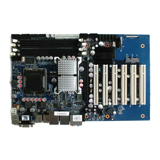
Page 28: Kt965/Atxe
KT965 Family KTD-00699-S Public User Manual Date: 2010-04-15 Page 28 of 90 4.1.3 KT965/ATXE DDR2 SLOT 4 ATX/ BTXPWR SATA0 SATA1 SATA2 SATA3 SATA4 SATA5 DDR2 SLOT 3 Clr-CMOS FRONTPNL DDR2 SLOT 2 FAN_SYS DDR2 SLOT 1 PCI Slot 1 FEATURE PRINTER PCI Slot 2... -
Page 29: Power Connector (Atxpwr)
KT965 Family KTD-00699-S Public User Manual Date: 2010-04-15 Page 29 of 90 Power Connector (ATXPWR) The KT965 boards are designed to be supplied from a standard ATX or BTX power supply. ATX/ BTX Power Connector: Pull Pull Note Ioh/Iol Type Signal Signal Type... -
Page 30: Keyboard And Ps/2 Mouse Connectors
KT965 Family KTD-00699-S Public User Manual Date: 2010-04-15 Page 30 of 90 Keyboard and PS/2 mouse connectors Attachment of a keyboard or PS/2 mouse adapter can be done through the stacked PS/2 mouse and keyboard connector (MSE & KBD). Both interfaces utilize open-drain signaling with on-board pull-up. The PS/2 mouse and keyboard is supplied from SB5V when in standby mode in order to enable keyboard or mouse activity to bring the system out from power saving states. -
Page 31: Display Connectors
KT965 Family KTD-00699-S Public User Manual Date: 2010-04-15 Page 31 of 90 Display Connectors The KT965 board family provides onboard Analog CRT interface. Addtionally the KT965 boards provides support for ADD2 cards through the onboard PCI Express x16 connector, with extension capability for support of DVI, LVDS, VGA, HDMI/UDI, TV-Out, etc. -
Page 32: Pci-Express Connectors
Depending on the board variant the KT965 boards further supports one 4-lane (x4) PCI Express port. The KT965/Flex supports one 16-lane (x16) PCI Express port and one 4-lane PCI Express (x16) port. The KT965/ATXP supports one 16-lane (x16) PCI Express port. -
Page 33: Pci-Express X4 In A X16 Connector
PEG_RXP[2] PEG_RXN[2] PEG_TXP[1] PEG_TXN[1] PEG_RXP[1] PEG_RXN[1] PEG_TXP[0] PEG_TXN[0] PEG_RXP[0] PEG_RXN[0] 4.5.2 PCI-Express x4 in a x16 connector The KT965/Flex and KT965/ATXE boards supports one 4-lane PCI Express (x16) port. Note Type Signal Signal Type Note +12V +12V +12V +12V +12V... - Page 34 KT965 Family KTD-00699-S Public User Manual Date: 2010-04-15 Page 34 of 90 (continues) PCIE_RXN[4]...
-
Page 35: Minipci-Express Connector
KT965 Family KTD-00699-S Public User Manual Date: 2010-04-15 Page 35 of 90 4.5.3 miniPCI-Express connector The KT965/ATXP board supports one miniPCI Express port compliant to the Mini PCI Specification, Revision 1.0. This allows for implementation for small form factor PCI cards also referred to as Mini PCI Cards. Note Type Signal... -
Page 36: Serial Ata Harddisk Interface
KT965 Family KTD-00699-S Public User Manual Date: 2010-04-15 Page 36 of 90 Serial ATA harddisk interface The KT965 boards have an integrated SATA Host controller that supports independent DMA operation on six ports and data transfer rates of up to 3.0Gb/s (300MB/s). The SATA controller supports AHCI mode and has integrated RAID functionality with support for RAID modes 0, 1, 5 and 10 (Linux O/S only support for RAID 0 and 1). -
Page 37: Printer Port Connector (Printer)
KT965 Family KTD-00699-S Public User Manual Date: 2010-04-15 Page 37 of 90 Printer Port Connector (PRINTER). The signal definition in standard printer port mode is as follows: Pull Pull Note Ioh/Iol Type Signal Signal Type Ioh/Iol Note (24)/24 OC(O) STB# AFD# OC(O) (24)/24... -
Page 38: Serial Ports
KT965 Family KTD-00699-S Public User Manual Date: 2010-04-15 Page 38 of 90 Serial Ports Two RS232 serial ports are available on the KT965 boards The typical interpretation of the signals in the COM ports is as follows: Signal Description Transmitte Data, sends serial data to the communication link. The signal is set to a marking state on hardware reset when the transmitter is empty or when loop mode operation is initiated. -
Page 39: Ethernet Connectors
KT965 Family KTD-00699-S Public User Manual Date: 2010-04-15 Page 39 of 90 Ethernet connectors. The KT965 boards supports 2 channels of 10/100/1000Mb Ethernet RTL8111B LAN controllers. In order to achieve the specified performance of the Ethernet port, Category 5 twisted pair cables must be used with 10/100MB and Category 5E, 6 or 6E with 1Gb LAN networks. -
Page 40: Ethernet Connector 2 (Ether2)
KT965 Family KTD-00699-S Public User Manual Date: 2010-04-15 Page 40 of 90 4.9.2 Ethernet connector 2 (ETHER2) Ethernet connector 2 is mounted together with USB Ports 4 and 5. The pinout of the RJ45’s connector are as follows: Signal Type Ioh/Iol Note MDI0+... -
Page 41: Usb Connector (Usb)
KT965 Family KTD-00699-S Public User Manual Date: 2010-04-15 Page 41 of 90 4.10 USB Connector (USB) The KT965 boards contains two Enhanced Host Controller Interface (EHCI) host controllers that supports USB 2.0 allowing data transfers up to 480Mb/s. The KT965 boards also contains five Universal Host Controller Interface (UHCI Revision 1.1) controllers that support USB full-speed and low-speed signaling. -
Page 42: Usb Connector 4/5 (Usb4/5)
KT965 Family KTD-00699-S Public User Manual Date: 2010-04-15 Page 42 of 90 4.10.2 USB Connector 4/5 (USB4/5) USB Ports 4 and 5 are mounted together with ETHER2. Pull Pull Note Ioh/Iol Type Signal Signal Type Ioh/Iol Note 5V/SB5V /15K 0.25/2 USB5- USB5+ 0.25/2... -
Page 43: Usb Connector 8/9 (Usb8/9)
KT965 Family KTD-00699-S Public User Manual Date: 2010-04-15 Page 43 of 90 4.10.4 USB Connector 8/9 (USB8/9) USB Ports 8 and 9 are available on the I/O frontpanel. Pull Pull Note Ioh/Iol Type Signal Signal Type Ioh/Iol Note 5V/SB5V /15K 0.25/2 USB8- USB8+... -
Page 44: Audio Connector
KT965 Family KTD-00699-S Public User Manual Date: 2010-04-15 Page 44 of 90 4.11 Audio Connector The onboard Audio circuit implements 7.1+2 Channel High Definition Audio with UAA (Universal Audio Architecture), featuring five 24-bit stereo DACs and three 20-bit stereo ADCs. 4.11.1 Audio Line-in, Line-out and Microphone Audio Line-in, Line-out and Microphone are available in the stacked audio jack connector. -
Page 45: Cd-Rom Audio Input (Cdrom)
KT965 Family KTD-00699-S Public User Manual Date: 2010-04-15 Page 45 of 90 4.11.2 CD-ROM Audio input (CDROM) CD-ROM audio input may be connected to this connector. It may also be used as a secondary line-in signal. Signal Type Ioh/Iol Pull Note CD_Left CD_GND... -
Page 46: Audio Header (Audio_Head)
KT965 Family KTD-00699-S Public User Manual Date: 2010-04-15 Page 46 of 90 4.11.3 AUDIO Header (AUDIO_HEAD) Pull Ioh/ Ioh/ Pull Note Type Signal Signal Type Note LFE-OUT CEN-OUT AAGND AAGND FRONT-OUT-L FRONT-OUT-R AAGND AAGND REAR-OUT-L REAR-OUT-R SIDE-OUT-L 11 12 SIDE-OUT-R AAGND 13 14 AAGND... -
Page 47: Fan Connectors , Fan_Cpu And Fan_Sys
KT965 Family KTD-00699-S Public User Manual Date: 2010-04-15 Page 47 of 90 4.12 Fan connectors , FAN_CPU and FAN_SYS. The FAN_CPU is used for connection of the active cooler for the CPU. The FAN_SYS can be used to power, control and monitor a fan for chassis ventilation etc. The 4pin header supports connection of 3-pin FANs, but it is recommended to use the 4-pin type for optimized FAN speed control. -
Page 48: The Clear Cmos Jumper, Clr-Cmos
KT965 Family KTD-00699-S Public User Manual Date: 2010-04-15 Page 48 of 90 4.13 The Clear CMOS Jumper, Clr-CMOS. The Clr-CMOS Jumper is used to clear the CMOS content. ↑ CPU location ↑ No Jumper installed (Pin numbers) Jumper normal position •... -
Page 49: Tpm Connector (Unsupported)
KT965 Family KTD-00699-S Public User Manual Date: 2010-04-15 Page 49 of 90 4.14 TPM connector (unsupported). Pull Pull Note Ioh/Iol Type Signal Signal Type Ioh/Iol Note LPC CLK LPC FRAME# LPC RST# LPC AD3 LPC AD2 +3V3 LPC AD1 LPC AD0 11 12 SMB_CLK 13 14... -
Page 50: Front Panel Connector (Frontpnl)
KT965 Family KTD-00699-S Public User Manual Date: 2010-04-15 Page 50 of 90 4.16 Front Panel connector (FRONTPNL). Pull Pull Note Ioh/Iol Type Signal Signal Type Ioh/Iol Note USB13_5V USB13_5V USB1- USB3- USB1+ USB3+ LINE2-IN-L 11 12 HD_LED 13 14 SUS_LED 15 16 PWRBTN_IN# RSTIN#... -
Page 51: Feature Connector (Feature)
General Purpose Inputs / Output. These Signals may be controlled or monitored through GPIO0..7 the use of the KONTRON API (Application Programming Interface) available for WinXP and Win2000. FAN 3 speed control OUTput. This analogue voltage output signal can be set to output FAN3OUT voltages from 0 –... -
Page 52: Pci Slot Connector
KT965 Family KTD-00699-S Public User Manual Date: 2010-04-15 Page 52 of 90 4.18 PCI Slot Connector Terminal Note Type Signal Signal Type Note -12V TRST# +12V INTA# INTB# INTC# INTD# REQ2# CLKC REQ3# +5V (I/O) GNT2# CLKD CLKA GNT3# RST# CLKB +5V (I/O) GNT0#... -
Page 53: Signal Description -Pci Slot Connector
KT965 Family KTD-00699-S Public User Manual Date: 2010-04-15 Page 53 of 90 4.18.1 Signal Description –PCI Slot Connector SYSTEM PINS Clock provides timing for all transactions on PCI and is an input to every PCI device. All other PCI signals, except RST#, INTA#, INTB#, INTC#, and INTD#, are sampled on the rising edge of CLK and all other timing parameters are defined with respect to this edge. - Page 54 KT965 Family KTD-00699-S Public User Manual Date: 2010-04-15 Page 54 of 90 ARBITRATION PINS (BUS MASTERS ONLY) Request indicates to the arbiter that this agent desires use of the bus. This is a point to point signal. Every REQ# master has its own REQ# which must be tri-stated while RST# is asserted. Grant indicates to the agent that access to the bus has been granted.
-
Page 55: Kt965 Pci Irq & Int Routing
Page 55 of 90 4.18.2 KT965 PCI IRQ & INT routing Board type Slot IDSEL INTA INTB INTC INTD AD16 INT_PIRQ#A INT_PIRQ#B INT_PIRQ#C INT_PIRQ#D KT965/FLEX AD17 INT_PIRQ#E INT_PIRQ#F INT_PIRQ#G INT_PIRQ#H AD16 INT_PIRQ#A INT_PIRQ#B INT_PIRQ#C INT_PIRQ#D KT965/ATXP AD17 INT_PIRQ#E INT_PIRQ#F INT_PIRQ#G... -
Page 56: Onboard Connectors
Molex 22-23-2061 Molex 22-01-2065 CDROM Foxconn HF1104E Molex 50-57-9404 Molex 70543-0038 SATA0-5 Molex 67491-0020 Molex 67489-8005 Kontron KT 821035 (cable kit) ATXPWR Molex 44-206-0002 Molex 39-01-2245 (24-pole) Molex 39-01-2205 (20-pole) COM2 Foxconn HL20051 Molex 90635-1103 Kontron KT 821016 (cable kit) -
Page 57: System Ressources
KT965 Family KTD-00699-S Public User Manual Date: 2010-04-15 Page 57 of 90 6. System Ressources Memory map Address range (hex) Size Description 00000000 0009FFFF 640K System board 000A0000 000BFFFF 128K Intel 965 Express Chipset Family 000A0000 000BFFFF 128K PCI bus 000C0000 000CFFFF 128K... -
Page 58: Pci Devices
KT965 Family KTD-00699-S Public User Manual Date: 2010-04-15 Page 58 of 90 PCI devices Device Function Vendor Device IDSEL Chip Device Function 8086h 2990h Host bridge 8086h 2992h VGA controller 8086h 2834h ICH8 8086h 2835h ICH8 8086h 283Ah ICH8 8086h 284Bh ICH8 HD-Audio... -
Page 59: Interrupt Usage
KT965 Family KTD-00699-S Public User Manual Date: 2010-04-15 Page 59 of 90 Interrupt Usage Notes • IRQ0 • IRQ1 • IRQ2 • 1, 2 IRQ3 • 1, 2 IRQ4 • 1, 2 IRQ5 • • • 1, 2 IRQ6 1, 2 IRQ7 •... -
Page 60: I/O Map
KT965 Family KTD-00699-S Public User Manual Date: 2010-04-15 Page 60 of 90 I/O Map Address (hex) Size Description 0020- 0021 Programmable interrupt controller 0040- 0043 System Timer 0060- 0060 Standard keyboard 0061- 0061 System speaker 0064- 0064 Standard keyboard 0070- 0071 System CMOS/Real time clock 0170-... -
Page 61: Dma Channel Usage
KT965 Family KTD-00699-S Public User Manual Date: 2010-04-15 Page 61 of 90 DMA Channel Usage DMA Channel Number Data Width System Ressources 8 or 16 bits Available 8 or 16 bits Available 8 or 16 bits Available 8 or 16 bits Available 8 or 16 bits DMA Controller... -
Page 62: Overview Of Bios Features
7. Overview of BIOS features This Manual section details specific BIOS features for the KT965 boards. The KT965 boards are based on the AMI BIOS core version 8.10 with Kontron BIOS extensions. System Management BIOS (SMBIOS / DMI) SMBIOS is a Desktop Management Interface (DMI) compliant method for managing computers in a managed network. -
Page 63: Bios Configuration / Setup
KT965 Family KTD-00699-S Public User Manual Date: 2010-04-15 Page 63 of 90 8. BIOS Configuration / Setup Introduction The BIOS Setup is used to view and configure BIOS settings for the KT965 board. The BIOS Setup is accessed by pressing the DEL key after the Power-On Self-Test (POST) memory test begins and before the operating system boot begins. -
Page 64: Advanced Menu
KT965 Family KTD-00699-S Public User Manual Date: 2010-04-15 Page 64 of 90 Advanced Menu BIOS SETUP UTILITY Main PCIPnP Boot Security Chipset Exit Advanced Configure CPU. Advanced Settings Warning: Setting wrong values in below sections may cause system to malfunction. ►... -
Page 65: Advanced Settings - Cpu Configuration
KT965 Family KTD-00699-S Public User Manual Date: 2010-04-15 Page 65 of 90 8.3.1 Advanced settings – CPU Configuration BIOS SETUP UTILITY Advanced Maximum: CPU Speed is Configure advanced CPU settings set to maximum. Module Version: 3F.07 Minimum: CPU Speed is set to minimum. -
Page 66: Advanced Settings - Ide Configuration
KT965 Family KTD-00699-S Public User Manual Date: 2010-04-15 Page 66 of 90 8.3.2 Advanced settings – IDE Configuration BIOS SETUP UTILITY Advanced Options IDE Configuration Sata#1 Configuration [Compatible] Disabled Configure SATA#1 as [IDE] Compatible Sata#2 Configuration [Enhanced] Enhanced Primary IDE Master : [Hard Disk] Secondary IDE Master : [Not Detected]... - Page 67 KT965 Family KTD-00699-S Public User Manual Date: 2010-04-15 Page 67 of 90 BIOS SETUP UTILITY Advanced Select the type of Primary IDE Master devices connected to Device :Hard Disk the system Vendor :ST340014A Size :40.0GB LBA Mode :Supported Block Mode :16Sectors PIO Mode Async DMA...
-
Page 68: Advanced Settings - Lan Configuration
KT965 Family KTD-00699-S Public User Manual Date: 2010-04-15 Page 68 of 90 8.3.3 Advanced settings – LAN Configuration BIOS SETUP UTILITY Advanced Control of Ethernet LAN Configuration Devices and PXE boot ETH1 Configuration (Right) [Enabled] MAC Address : 00E0F4000001 100MB* ETH2 Configuration (Left) [Enabled] MAC Address... -
Page 69: Advanced Settings - Super Io Configuration
KT965 Family KTD-00699-S Public User Manual Date: 2010-04-15 Page 69 of 90 8.3.4 Advanced settings – Super IO Configuration BIOS SETUP UTILITY Advanced Allows BIOS to Select Configure Win627DHG Super IO Chipset Serial Port1 Base Serial Port1 Address [3F8/IRQ4] Addresses. Serial Port2 Address [2F8/IRQ3] Serial Port2 Mode... -
Page 70: Advanced Settings - Hardware Health Configuration
KT965 Family KTD-00699-S Public User Manual Date: 2010-04-15 Page 70 of 90 8.3.5 Advanced settings – Hardware Health Configuration BIOS SETUP UTILITY Advanced Disable = Full Speed Hardware Health Configuration System Temperature :37ºC/98ºF Thermal: Does regulate CPU Temperature :43ºC/109ºF fan speed according to specified temperature SYSFAN Speed :Fail... -
Page 71: Advanced Settings - Voltage Monitor
KT965 Family KTD-00699-S Public User Manual Date: 2010-04-15 Page 71 of 90 8.3.6 Advanced settings – Voltage Monitor BIOS SETUP UTILITY Advanced Enable Hardware Health Voltage Monitor Monitoring Device. Requested Core :1.2750 V Vcore :1.248 V AVCC :3.232 V 3VCC :3.232 V +12Vin :12.083 V... -
Page 72: Advanced Settings - Acpi Configuration
KT965 Family KTD-00699-S Public User Manual Date: 2010-04-15 Page 72 of 90 8.3.7 Advanced settings – ACPI Configuration BIOS SETUP UTILITY Advanced Enable RSDP pointers ACPI Settings To 64-bit Fixed System Description Tabled. ACPI Version Features [V1.0] Different ACPI version Repost Video on S3 Resume [No] has some addition. -
Page 73: Advanced Settings - Apm Configuration
KT965 Family KTD-00699-S Public User Manual Date: 2010-04-15 Page 73 of 90 8.3.8 Advanced settings – APM Configuration BIOS SETUP UTILITY Advanced Enable or disable APM. APM Configuration Power Management/APM [Enabled] Advanced Resume Event Controls Resume On Ring [Disabled] Resume On PME# [Disabled] Resume On RTC Alarm [Disabled]... -
Page 74: Pci Express Configuration
KT965 Family KTD-00699-S Public User Manual Date: 2010-04-15 Page 74 of 90 8.3.9 PCI Express Configuration BIOS SETUP UTILITY Advanced Enable/Disable PCI Express Configuration PCI Express L0s and L1 link power states. Active State Power-Management [Disabled] <- Select Screen Select Item change option General Help Save and Exit... -
Page 75: Advanced Settings - Remote Access Configuration
KT965 Family KTD-00699-S Public User Manual Date: 2010-04-15 Page 75 of 90 8.3.10 Advanced settings – Remote Access Configuration BIOS SETUP UTILITY Advanced Select Remote Access Configure Remote Access type and parameters type. Remote Access [Enabled] Serial port number [COM1] Base Address, IRQ [3F8h, 4] Serial Port Mode... -
Page 76: Advanced Settings - Tcg/Tpm Support
KT965 Family KTD-00699-S Public User Manual Date: 2010-04-15 Page 76 of 90 8.3.11 Advanced settings – TCG/TPM support BIOS SETUP UTILITY Advanced Enable/Disable TPM TCG Trusted Computing (TPM 1.1/1.2) support in BIOS TCG/TPM SUPPORT [Yes] Execute TPM Command [Don’t change] Clearing the TPM [Press Enter] TPM Enable/Disable Status... -
Page 77: Advanced Settings - Usb Configuration
KT965 Family KTD-00699-S Public User Manual Date: 2010-04-15 Page 77 of 90 8.3.12 Advanced settings – USB Configuration BIOS SETUP UTILITY Advanced Enables support for USB Configuration legacy USB. AUTO Module Version – 2.24.0-12.4 option disables if no USB Devices are connected. -
Page 78: Advanced Settings - Usb Mass Storage Device Configuration
KT965 Family KTD-00699-S Public User Manual Date: 2010-04-15 Page 78 of 90 8.3.13 Advanced settings – USB Mass Storage Device Configuration BIOS SETUP UTILITY Advanced Number of seconds POST USB Mass Storage Device Configuration waits for the USB mass USB Mass Storage Reset Delay [20 Sec] storage device after Emulation Type Default... -
Page 79: Pcipnp Menu
KT965 Family KTD-00699-S Public User Manual Date: 2010-04-15 Page 79 of 90 PCIPnP Menu BIOS SETUP UTILITY PCIPnP NO: lets the BIOS Advanced PCI/PnP Settings configure all the devices in the system. Warning: Setting wrong values in below sections YES: lets the May cause system to malfunction. -
Page 80: Boot Menu
KT965 Family KTD-00699-S Public User Manual Date: 2010-04-15 Page 80 of 90 Boot Menu BIOS SETUP UTILITY Main Advanced PCIPnP Security Chipset Exit Boot Configure Settings Boot Settings during System Boot. ► Boot Settings Configuration ► Boot Device Priority <- Select Screen Select Item Enter Go to Sub Screen... -
Page 81: Boot - Boot Settings Configuration
KT965 Family KTD-00699-S Public User Manual Date: 2010-04-15 Page 81 of 90 8.5.1 Boot – Boot Settings Configuration BIOS SETUP UTILITY Boot Configure Settings Boot Settings Configuration during System Boot. Quick Boot [Enabled] Quiet Boot [Disabled] AddOn ROM Display Mode [Force BIOS] Bootup Num-Lock [On]... -
Page 82: Boot - Boot Device Priority
KT965 Family KTD-00699-S Public User Manual Date: 2010-04-15 Page 82 of 90 Note: List of errors: <INS> Pressed Primary Master Hard Disk Error PCI I/O conflict Timer Error S.M.A.R.T HDD Error PCI ROM conflict Interrupt Controller-1 error Cache Memory Error PCI IRQ conflict Keyboard/Interface Error DMA Controller Error... -
Page 83: Security Menu
KT965 Family KTD-00699-S Public User Manual Date: 2010-04-15 Page 83 of 90 Security Menu BIOS SETUP UTILITY Main Advanced PCIPnP Boot Chipset Exit Security Install or Change the Security Settings password. Supervisor Password :Installed User Password :Installed Change Supervisor Password Change User Password Boot Sector Virus Protection [Disabled]... -
Page 84: Chipset Menu
KT965 Family KTD-00699-S Public User Manual Date: 2010-04-15 Page 84 of 90 Chipset Menu BIOS SETUP UTILITY Main Advanced PCIPnP Boot Security Exit Chipset Configures North Advanced Chipset Settings Bridge features. Warning: Setting wrong values in below sections may cause system to malfunction. ►... -
Page 85: Advanced Chipset Settings - North Bridge Chipset Configuration
KT965 Family KTD-00699-S Public User Manual Date: 2010-04-15 Page 85 of 90 8.7.1 Advanced Chipset Settings – North Bridge Chipset Configuration BIOS SETUP UTILITY Chipset ENABLE: Allow remapping of North Bridge Chipset Configuration overlapped PCI memory Memory Remap Feature [Enabled] above the total physical PCI MMIO Allocation : 4GB To 2816MB memory... -
Page 86: Advanced Chipset Settings - Video Function Configuration
KT965 Family KTD-00699-S Public User Manual Date: 2010-04-15 Page 86 of 90 8.7.2 Advanced Chipset Settings – Video Function Configuration BIOS SETUP UTILITY Chipset Video Function Configuration Fixed Mode DVMT Mode Select [DVMT Mode] DVMT Mode DVMT/ Fixed Memory [256MB] Boot Type: [AUTO] EDID Support... -
Page 87: Advanced Chipset Settings - Southbridge Configuration
KT965 Family KTD-00699-S Public User Manual Date: 2010-04-15 Page 87 of 90 8.7.3 Advanced Chipset Settings – SouthBridge Configuration BIOS SETUP UTILITY Chipset Disabled South Bridge Chipset Configuration 2 USB Ports 4 USB Ports USB Functions [10 USB Ports] 6 USB Ports USB 2.0 Controller [Enabled] 8 USB Ports... -
Page 88: Exit Menu
KT965 Family KTD-00699-S Public User Manual Date: 2010-04-15 Page 88 of 90 Exit Menu BIOS SETUP UTILITY Main Advanced PCIPnP Boot Security Chipset Exit Exit system setup Exit Options after saving the changes. Save Changes and Exit Discard Changes and Exit F10 Key can be used Discard Changes for this operation. -
Page 89: Ami Bios Beep Codes
KT965 Family KTD-00699-S Public User Manual Date: 2010-04-15 Page 89 of 90 AMI BIOS Beep Codes Boot Block Beep Codes: Number of Description Beeps Insert diskette in floppy drive A: ‘AMIBOOT.ROM’ file not found in root directory of diskette in A: Base Memory error Flash Programming successful Floppy read error... -
Page 90: Ktd-00699-S
Before installing Windows XP SP3 be sure to use BIOS version 011 (KT965011) or above. 10. Warranty KONTRON Technology warrants its products to be free from defects in material and workmanship during the warranty period. If a product proves to be defective in material or workmanship during the warranty period, KONTRON Technology will, at its sole option, repair or replace the product with a similar product.
Need help?
Do you have a question about the KT965/ATXE and is the answer not in the manual?
Questions and answers