Wacker Neuson BS 60-4s Operator's Manual
Rammer
Hide thumbs
Also See for BS 60-4s:
- Operator's manual (48 pages) ,
- Operator's manual (42 pages) ,
- Operator's manual (40 pages)
Table of Contents
Advertisement
Advertisement
Table of Contents

Related Manuals for Wacker Neuson BS 60-4s


Summary of Contents for Wacker Neuson BS 60-4s
- Page 1 Operator’s Manual Rammer BS 60-4s 0170873en 0410...
- Page 2 This publication may be photocopied by the original purchaser of the machine. Any other type of reproduction is prohibited without express written permission from Wacker Neuson Corporation. Any type of reproduction or distribution not authorized by Wacker Neuson Corporation represents an infringement of valid copyrights. Violators will be prosecuted. Trademarks All trademarks referenced in this manual are the property of their respective owners.
-
Page 3: Foreword
Refer to the separate Repair Manual for detailed instructions on servicing and repairing the machine. If you are missing any of these documents, please contact Wacker Neuson Corporation to order a replacement or visit www.wackerneuson.com. When ordering parts or requesting service information, be prepared to provide the machine model number, item number, revision number, and serial number. - Page 4 Serious injury hazards to the operator and persons in the work area Permanent damage to the machine which will not be covered under warranty Contact your Wacker Neuson dealer immediately if you have questions about approved or unapproved parts, attachments, or modifications.
-
Page 5: Table Of Contents
BS 60-4s Table of Contents Foreword Emission Control System Information Safety Information Signal Words Found in this Manual ............ 14 Machine Description and Intended Use ..........15 Operating Safety ................16 Operator Safety while using Internal Combustion Engines ....18 Service Safety .................. - Page 6 Table of Contents BS 60-4, BS 60-4s Maintenance Periodic Maintenance Schedule ............33 Servicing Air Cleaner ................34 Engine Oil ....................35 Checking and Changing the Ramming System Oil ......36 Shoe Hardware ...................38 Long-Term Storage ................39 Basic Troubleshooting Tech Data Rammer ....................43 Sound Measurements .................44 Vibration Measurements ..............44...
-
Page 7: Emission Control System Information
Carbon monoxide does not react in the same way, but it is toxic. Wacker Neuson utilizes lean carburetor settings and other systems to reduce the emissions of carbon monoxide, oxides of nitrogen, and hydrocarbons. - Page 8 Emission Control System Information Replacement Parts The emission control systems on your Wacker Neuson engine were designed, built, and certified to conform with EPA and California emissions regulations. We recommend the use of genuine Wacker Neuson parts whenever you have maintenance done. These original- design replacement parts are manufactured to the same standards as the original parts, so you can be confident of their performance.
- Page 9 Emission Control System Information METHANOL - (methyl or wood alcohol) 5% by volume. You may use gasoline containing up to 5% methanol by volume, as long as it contains cosolvents and corrosion inhibitors to protect the fuel system. Gasoline containing more than 5% methanol by volume may cause starting and/or performance problems.
- Page 10 For the components listed under PARTS COVERED, the service dealer authorized by Wacker Neuson will, at no cost to you, make the necessary diagnosis, repair, or replacement necessary to ensure that the engine complies with applicable U.S. EPA regulations.
- Page 11 Emission Control System Information PARTS COVERED Listed below are the parts covered by the Emission Components Defect Warranty. Some of the parts listed below may require scheduled maintenance and are warranted up to the first scheduled replacement point for that part. (1) Fuel Metering System (i) Carburetor and internal parts (and/or pressure regulator or fuel injection system).
- Page 12 Wacker Neuson recommends that you retain all receipts covering maintenance on your engine, but Wacker Neuson cannot deny warranty solely for the lack of receipts or for your failure to ensure the performance of all scheduled maintenance.
- Page 13 MAY HAVE A BEARING ON THE OUTCOME OF A WARRANTY CLAIM. If other than the parts authorized by Wacker Neuson are used for maintenance replacements or for the repair of components affecting emission control, you should assure yourself that such parts are warranted by their manufacturer to be equivalent to the parts authorized by Wacker Neuson in their performance and durability.
-
Page 14: Safety Information
Safety Information BS 60-4 Safety Information Signal Words Found in this Manual This manual contains DANGER, WARNING, CAUTION, NOTICE, and NOTE signal words which must be followed to reduce the possibility of personal injury, damage to the equipment, or improper service. This is the safety alert symbol. -
Page 15: Machine Description And Intended Use
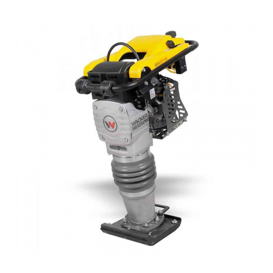
Safety Information Machine Description and Intended Use This machine is a vibratory rammer. The Wacker Neuson Rammer consists of a gasoline or diesel engine, a clutch, a fuel tank, a spring- loaded ramming system, a ramming shoe, and a handle. The engine transmits power through the ramming system and ramming shoe, generating percussive impact force to compact soil. -
Page 16: Operating Safety
• Familiarize yourself with the location and proper use of all controls and safety devices. • Contact Wacker Neuson Corporation for additional training if necessary. When operating this machine: • Do not allow improperly trained people to operate the machine. - Page 17 BS 60-4 Safety Information 2.3.5 Never leave the machine running unattended. 2.3.6 Never tamper with or disable the function of operating controls. 2.3.7 Never use the choke to stop the engine. 2.3.8 Never operate the machine in areas where explosions may occur. 2.3.9 Read, understand, and follow procedures in the Operator’s Manual before attempting to operate the machine.
-
Page 18: Operator Safety While Using Internal Combustion Engines
Safety Information BS 60-4 Operator Safety while using Internal Combustion Engines WARNING Internal combustion engines present special hazards during operation and fueling. Failure to follow the warnings and safety standards could result in severe injury or death. Read and follow the warning instructions in the engine owner’s manual and the safety guidelines below. -
Page 19: Service Safety
• Only trained personnel shall troubleshoot or repair problems occurring with the machine. • Contact Wacker Neuson Corporation for additional training if necessary. When servicing or maintaining this machine: • Do not allow improperly trained people to service or maintain the machine. - Page 20 2.5.11 ALWAYS clean debris from engine cooling fins. 2.5.12 When replacement parts are required for this machine, use only Wacker Neuson replacement parts or those parts equivalent to the original in all types of specifications, such as physical dimensions, type, strength, and material.
- Page 21 BS 60-4 Safety Information Notes wc_si000440gb.fm...
-
Page 22: Labels
Labels BS 60-4s Labels Label Locations wc_gr007427 wc_si000494gb.fm... -
Page 23: Label Meanings
BS 60-4s Labels Label Meanings Label Meaning To start the machine: 1. Move the throttle to the IDLE position. 2. Push the purge bulb 10 times. 3. Close the choke. 4. Pull the starter rope until engine starts. 5. Move the throttle to the FAST position. - Page 24 Labels BS 60-4s Label Meaning WARNING! Hot surface! Warning! Springs are compressed. Release cover slowly to avoid spring ejection. See the Repair Manual for proper disassembly instructions. For optimal control, performance, and minimal hand/arm vibration, grasp handle as shown. Read the Operator’s Manual.
- Page 25 BS 60-4s Labels Label Meaning Guaranteed sound power level in dB(A). CAUTION! Use only clean, filtered gasoline fuel. This label is molded into the cover. If it becomes illegible, the cover must be replaced. Refer to the Parts Book for ordering information.
- Page 26 Labels BS 60-4s Label Meaning This rammer is equipped with a low oil shutoff switch, it will not allow the engine to operate unless a sufficient amount of oil is present. See section Low Oil Shutoff Switch. This machine may be covered by one or more pat- ents.
-
Page 27: Lifting And Transporting
WARNING immediately to avoid injury or death. 4.1.4 Wacker Neuson recommends transporting rammers upright whenever possible; however, a rammer should not be allowed to fall over. If the rammer cannot be secured in the upright position, tie down the rammer to the transport vehicle to prevent it from tipping, falling, or rolling. -
Page 28: Operation
5.1.2 Check the machine and its components for damage. If there is visible damage, do not operate the machine! Contact your Wacker Neuson dealer immediately for assistance. 5.1.3 Take inventory of all items included with the machine and verify that all loose components and fasteners are accounted for. -
Page 29: Position Of The Operator
BS 60-4s Operation Position of the Operator For optimal control, performance, and minimal hand/arm vibration follow the guidelines below when using the machine. • Grasp the handle with both hands as shown. Hand/Arm Vibration (HAV) has been opti- mized for the hand position shown. -
Page 30: Before Starting
Operation BS 60-4s Before Starting 5.4.1 Read safety instructions at the beginning of this manual. 5.4.2 Make sure that the gas tank is full. 5.4.3 Check engine oil level. 5.4.4 Place rammer on loose soil or gravel. DO NOT start rammer on hard surfaces such as asphalt or concrete. -
Page 31: To Stop
BS 60-4s Operation To Stop See Graphic: wc_gr007426 5.6.1 Place throttle in the idle position (c2). 5.6.2 Shut off the engine by moving the throttle through the detent to the off position (c1). The engine will stop and the fuel valve will close. -
Page 32: Low Oil Shutoff Switch
Operation BS 60-4s Low Oil Shutoff Switch The low oil shutoff switch is designed to prevent engine damage caused by an insufficient amount of oil. When starting the machine: • if the warning light flashes quickly once, this indicates the engine oil level is acceptable. -
Page 33: Maintenance
BS 60-4s Maintenance Maintenance Periodic Maintenance Schedule The table below lists basic machine maintenance. Tasks designated with check marks may be performed by the operator. Tasks designated with square bullet points require special training and equipment. Every Every Every Daily... -
Page 34: Servicing Air Cleaner
Maintenance BS 60-4s Servicing Air Cleaner See Graphic: wc_gr001306 NEVER use gasoline or other types of low flash point solvents for cleaning the air filter. A fire or explosion could result. WARNING NOTICE: NEVER run the engine without the main paper air filter (b). -
Page 35: Engine Oil
BS 60-4s Maintenance Engine Oil See Graphic: wc_gr002431 6.3.1 Drain the oil while the engine is still warm. Note: In the interests of environmental protection, place a plastic sheet and a container under the machine to collect any liquid which drains off. -
Page 36: Checking And Changing The Ramming System Oil
Maintenance BS 60-4s Checking and Changing the Ramming System Oil Background Lubricating oil is distributed throughout the ramming system by the action of the rammer. Holes drilled in the piston carry oil from the bottom of the rammer to the crankcase as the rammer operates. Oil in the ramming system must be maintained at the correct level to ensure the ramming system operates efficiently. - Page 37 BS 60-4s Maintenance 6.4.4 Remove the sightglass. Clean the threads of the sightglass, then wrap the threads with teflon tape. 6.4.5 Add oil to the machine through the sightglass opening in the housing. 6.4.6 Stand the machine upright to check the oil level. Add enough oil so that when the machine is upright, oil will fill 1/2 to 3/4 of the sightglass.
-
Page 38: Shoe Hardware
Maintenance BS 60-4s Shoe Hardware See Graphic: wc_gr000048 On new machines, or after replacing shoe, check and tighten shoe hardware (a) after the first 5 hours of operation. Inspect hardware every week thereafter. Torque hardware as specified. 8 6 N m ( 6 3 f t . -
Page 39: Long-Term Storage
BS 60-4s Maintenance Long-Term Storage Introduction Extended storage of equipment requires preventative maintenance. Performing these steps helps to preserve machine components and ensures the machine will be ready for future use. While not all of these steps necessarily apply to this machine, the basic procedures remain the same. - Page 40 Maintenance BS 60-4s Storing the machine Perform these remaining steps to store your machine. • Wash the machine and allow it to dry. • Move the machine to a clean, dry, secure storage location. Block or chock wheels to prevent machine movement.
-
Page 41: Basic Troubleshooting
BS 60-4s Basic Troubleshooting Basic Troubleshooting Problem / Symptom Reason / Remedy Engine does not start, or • No fuel in tank. stalls. • Check engine oil level. • Spark plug fouled. • Fuel valve closed. Engine does not accelerate, is •... - Page 42 Basic Troubleshooting BS 60-4s Problem / Symptom Reason / Remedy On machines equipped with • Check the switch for proper wire connections. the low oil shutoff switch, the • Switch is not functioning properly. Replace the engine starts and continues to switch.
-
Page 43: Tech Data
BS 60-4s Tech Data Tech Data Rammer Engine power rating Gross power rating per SAE J1995. Actual power output may vary due to conditions of specific use. BS 60-4s 0620323 0620073 0620388 0620813 0620816 0620387 0620819 0620820 Engine Model type... -
Page 44: Sound Measurements
Tech Data BS 60-4s Sound Measurements Products are tested for sound pressure level in accordance with EN ISO 11204. Sound power level is tested in accordance with European Directive 2000/14/EC - Noise Emission in the Environment by Equipment for use outdoors. -
Page 45: Dimensions
BS 60-4s Tech Data Dimensions mm (in.) (26.5) (38) (11.0) (13.0) wc_td000406gb.fm... - Page 47 EC DECLARATION OF CONFORMITY WACKER NEUSON CORPORATION, N92W15000 ANTHONY AVENUE, MENOMONEE FALLS, WISCONSIN USA AUTHORIZED REPRESENTATIVE IN THE EUROPEAN UNION Axel Häret WACKER NEUSON SE Preußenstraße 41 80809 München hereby certifies that the construction equipment specified hereunder: Category: Vibratory Rammer Machine function: This machine is intended to be used for compacting cohesive, mixed, and granular soils in confined areas.
Need help?
Do you have a question about the BS 60-4s and is the answer not in the manual?
Questions and answers