Table of Contents
Advertisement
Quick Links
Advertisement
Table of Contents

Related Manuals for Wacker Neuson BS 65-V


Summary of Contents for Wacker Neuson BS 65-V
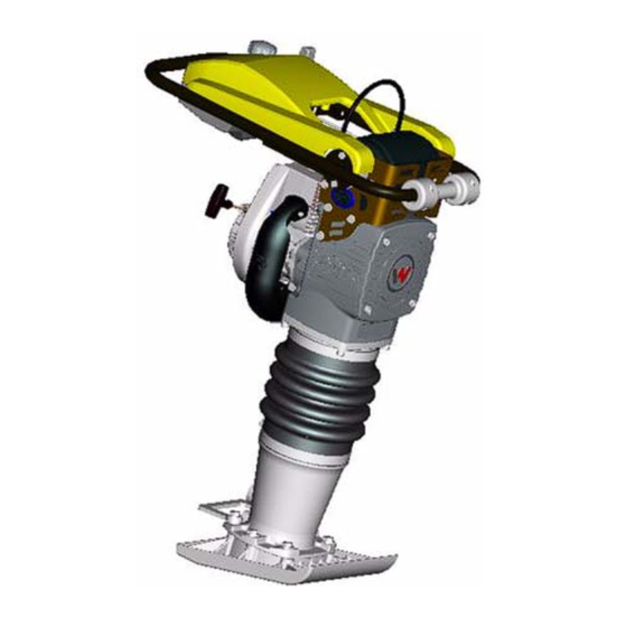
- Page 1 0176651en 0808 Rammer BS 65-V OPERATOR’S MANUAL...
-
Page 3: Table Of Contents
BS 65V Table of Contents Foreword Emission Control System Information Safety Information Laws Pertaining to Spark Arresters ............ 13 Operating Safety ................14 Operator Safety while using Internal Combustion Engines ....16 Service Safety ..................17 Label Locations .................. 18 Safety and Operating Labels .............. - Page 4 Table of Contents BS 65V Technical Data Rammer ....................41 Sound Measurements .................42 Vibration Measurements ..............42 Dimensions ..................42 wc_bo0176651en_001TOC.fm...
- Page 5 0009423 Rev 200 and higher This manual provides information and procedures to safely operate and maintain this Wacker Neuson model. For your own safety and protection from injury, carefully read, understand and observe the safety instructions described in this manual.
- Page 6 Foreword CALIFORNIA Proposition 65 Warning: Engine exhaust, some of its constituents, and certain vehicle components, contain or emit chemicals known to the State of WARNING California to cause cancer and birth defects or other reproductive harm. wc_tx000913gb.fm...
- Page 7 Carbon monoxide does not react in the same way, but it is toxic. Wacker Neuson utilizes lean carburetor settings and other systems to reduce the emissions of carbon monoxide, oxides of nitrogen, and hydrocarbons.
- Page 8 Emission Control System Information Replacement Parts The emission control systems on your Wacker Neuson engine were designed, built, and certified to conform with EPA and California emissions regulations. We recommend the use of genuine Wacker Neuson parts whenever you have maintenance done. These original- design replacement parts are manufactured to the same standards as the original parts, so you can be confident of their performance.
- Page 9 YOUR WARRANTY RIGHTS AND OBLIGATIONS All States Wacker Neuson must warrant the emission control system on your engine for the period of time listed below provided there has been no abuse, neglect or improper maintenance of your engine. Where a warrantable condition exists, Wacker Neuson will repair your engine at no cost to you including diagnosis, parts and labor.
- Page 10 Warranty repairs will be made without charge for diagnosis, parts or labor. All defective parts replaced under this warranty become property of Wacker Neuson. A list of warranted parts is located on the next page. Normal maintenance items, such as spark plugs and filters, that are on the warranted parts list are warranted up to the required replacement interval only.
- Page 11 Emission Control System Information TO OBTAIN WARRANTY SERVICE: You must take your Wacker Neuson product along with proof of original purchase date, at your expense, to any Wacker Neuson authorized dealer during their normal business hours. Claims for repair or adjustment found to be caused solely by defects in material or workmanship will not be denied because the engine was not properly maintained and used.
- Page 12 Emission Control System Information SYSTEMS COVERED PARTS BY THIS WARRANTY DESCRIPTIONS FUEL METERING CARBURETOR ASSEMBLY EXHAUST SYSTEM MUFFLER AIR INDUCTION AIR FILTER HOUSING AIR FILTER ELEMENT* IGNITION FLYWHEEL MAGNETO IGNITION MODULE SPARK PLUG CAP SPARK PLUG* MISCELLANEOUS TUBING, FITTINGS, SEALS, GASKETS PARTS AND CLAMPS ASSOCIATED WITH THESE LISTED ITEMS...
-
Page 13: Safety Information
BS 65-V Safety Information Safety Information This manual contains DANGER, WARNING, CAUTION, NOTICE and NOTE callouts which must be followed to reduce the possibility of personal injury, damage to the equipment, or improper service. This is the safety alert symbol. It is used to alert you to potential personal injury hazards. -
Page 14: Operating Safety
These areas get hot and may cause burns. 3.2.4 NEVER use accessories or attachments that are not recommended by Wacker Neuson. Damage to equipment and injury to the user may result. 3.2.5 NEVER leave the machine running unattended. - Page 15 BS 65-V Safety Information 3.2.17 ALWAYS be sure the rammer will not tip over, roll, slide, or fall when not being operated. 3.2.18 ALWAYS turn the engine OFF when the rammer is not being operated. 3.2.19 ALWAYS guide the rammer in such a way that the operator is not squeezed between the rammer and solid objects.
-
Page 16: Operator Safety While Using Internal Combustion Engines
Safety Information BS 65-V Operator Safety while using Internal Combustion Engines Internal combustion engines present special hazards during operation and fueling. Read and follow the warning instructions in the engine owner’s manual and the safety guidelines below. Failure to follow the DANGER warnings and safety standards could result in severe injury or death. -
Page 17: Service Safety
3.4.11 ALWAYS clean debris from engine cooling fins. 3.4.12 ALWAYS replace worn or damaged components with spare parts designed and recommended by Wacker Neuson Corporation. 3.4.13 ALWAYS disconnect the spark plug on machines equipped with gasoline engines, before servicing, to avoid accidental start-up. -
Page 18: Label Locations
Safety Information BS 65-V Label Locations wc_gr005418 wc_si000275gb.fm... -
Page 19: Safety And Operating Labels
BS 65-V Safety Information Safety and Operating Labels Wacker Neuson machines use international pictorial labels where needed. These labels are described below: Ref. Label Meaning This molded-in label contains important safety and operating information. If it becomes illegible, the cover must be replaced. Refer to the Parts Book for ordering information. - Page 20 Safety Information BS 65-V Ref. Label Meaning Pull the rewind starter. Open the choke. Place the throttle control lever in the “stop” position. Throttle control lever: 0 = Stop Turtle = Start or Idle Rabbit = Full or Fast DANGER! Engines emit carbon monoxide;...
- Page 21 BS 65-V Safety Information Ref. Label Meaning DANGER! No sparks, flames or burning objects near machine. Shut off the engine before refueling. CAUTION! Use only clean, filtered gasoline fuel. WARNING! To prevent hearing loss, wear hearing protection when operating the machine.
- Page 22 Safety Information BS 65-V Ref. Label Meaning For optimal control, performance, and minimal hand/arm vibration, grasp handle as shown. Refer to Section Proper Operation for further details. Guaranteed sound power level in dB(A). The air intake system is equipped with a filter indicator, which indicates when a filter change is required.
- Page 23 50:1-100:1 ratio. This rammer engine requires a two-cycle gasoline/oil mixture (50:1) With standard two-cycle oil use 50:1 ratio. With Wacker Neuson two-cycle or other oil meeting the NMMA TC-W3 specification, a ratio from 50:1 to 100:1 can be used. Refer to Selecting Ramming Stroke and Adjusting Ramming Stroke for explanation of these labels.
-
Page 24: Operation
This rammer engine requires a two-cycle gasoline/oil mixture. With standard two-cycle oil use 50:1 ratio. With Wacker Neuson two-cycle or other oil meeting the NMMA TC-W3 specification, a ratio from 50:1 to 100:1 can be used. Mix regular unleaded gasoline and two-cycle/outboard motor oil in separate container before filling tank. -
Page 25: To Start
BS 65-V Operation To Start See Graphic: wc_gr005324 4.4.1 Open throttle to full position (c4). This will automatically turn on the flow of fuel. 4.4.2 If machine is equipped, pump the purge bulb (e) 6 to 10 times or until you see fuel in bulb. -
Page 26: To Stop
Operation BS 65-V To Stop See Graphic: wc_gr005324 4.5.1 Place throttle in the idle position (c2). 4.5.2 Shut off the engine by moving the throttle through the detent to the off position (c1). The engine will stop and the fuel valve will close. -
Page 27: Proper Compaction
BS 65-V Operation Proper Compaction See Graphic: wc_gr000045 4.7.1 Open the throttle completely (a4) then adjust for maximum performance. Do not overthrottle. Best compaction is acheived when the rammer is running smoothly. Normally, a low stroke setting requires a lower engine speed. -
Page 28: Selecting Ramming Stroke
Operation BS 65-V Selecting Ramming Stroke The length of the ramming stroke directly affects the impact force delivered by the rammer. Selecting the best level depends on job requirements and soil conditions. The label located inside the front cover indicates the general compaction application, together with approximate throttle settings and impact levels for each stroke level. - Page 29 BS 65-V Operation Notes: wc_tx000918gb.fm...
-
Page 30: Adjusting Ramming Stroke
Operation BS 65-V Adjusting Ramming Stroke See Graphic: wc_gr000060 When adjusting the ramming stroke, observe the following precautions to avoid injury to yourself and others. Adjust stroke with machine standing upright and resting on a firm, level surface. Do not adjust stroke if the machine is in an unstable position where it can easily tip or slide. - Page 31 BS 65-V Operation NEVER operate the rammer with the stroke adjusting cover open. The locking lever rotates rapidly and could catch on skin or clothing, causing injury. CAUTION wc_tx000918gb.fm...
-
Page 32: Maintenance
Maintenance BS 65-V Maintenance Periodic Maintenance Schedule After Every Every Every Daily first week month 3 months Every before or 25 or 100 or 300 Year starting hours hours hours hours Check fuel level. Check air filter indicator. Replace as needed. -
Page 33: Air Cleaner
BS 65-V Maintenance Air Cleaner See Graphic: wc_gr001168 NEVER use gasoline or other types of low flash point solvents for cleaning the air filter. A fire or explosion could result. WARNING NOTICE: NEVER run engine without main paper filter element (b). -
Page 34: Lubrication
Maintenance BS 65-V Lubrication See Graphic: wc_gr005326 Ramming system Check oil level: 5.3.1 Tilt the machine backwards approximately 15° until the engine is level by placing a wedge under the shoe. 5.3.2 Check the oil level through oil sightglass (d). Proper ramming system lubrication is indicated when approximately 1/2–3/4 of the sightglass is... - Page 35 BS 65-V Maintenance wc_gr005326 wc_tx000923gb.fm...
-
Page 36: Fuel Lines
Maintenance BS 65-V Fuel Lines See Graphic: wc_gr005327 ALWAYS follow the instructions when disconnecting the fuel lines. Failure to do so may result in fuel leaking from the fuel system. CAUTION To disconnect the fuel lines: 5.4.1 Shut off the engine by moving the throttle through the detent to the off position (a). -
Page 37: Shoe Hardware
BS 65-V Maintenance Shoe Hardware See Graphic: wc_gr005389 On new machines, or after replacing shoe, check and tighten shoe hardware after the first 5 hours of operation. Inspect hardware every week thereafter. Torque hardware as specified. wc_gr005389 Torque Ft.lbs. wc_tx000923gb.fm... -
Page 38: Carburetor Adjustments
Maintenance BS 65-V Carburetor Adjustments See Graphic: wc_gr004670 Refer to Technical Data for correct idle and operating rpm. For best accuracy, use a tachometer when making carburetor adjustments. 5.6.1 Start engine and allow it to warm up to operating temperature. -
Page 39: Transportation
BS 65-V Maintenance Transportation See Graphic: wc_gr005328 5.8.1 Always shut off the engine and close the fuel valve when transporting the machine. 5.8.2 Make sure the lifting device has enough capacity to hold the machine (see identification plate on the machine for weight). -
Page 40: Troubleshooting
Maintenance BS 65-V Troubleshooting Problem / Symptom Reason / Remedy Engine does not start, or • No fuel in tank. stalls. • Spark plug fouled. • Fuel valve closed. Engine does not accelerate, is • Improper fuel mix. Too much oil. - Page 41 Three stage with cyclonic precleaner type Engine lubrication With standard two-cycle oil use 50:1 ratio. oil grade With Wacker Neuson two-cycle or other oil meeting the NMMA TC-W3 specification, a ratio from 50:1 to 100:1 can be used. Fuel tank capacity 3.0 (3.2) l (qts.)
- Page 42 Technical Data BS 65-V Sound Measurements Products are tested for sound pressure level in accordance with EN ISO 11204. Sound power level is tested in accordance with European Directive 2000/14/EC - Noise Emission in the Environment by Equipment for use outdoors.
- Page 43 EC DECLARATION OF CONFORMITY CE-KONFORMITÄTSERKLÄRUNG DECLARACIÓN DE CONFORMIDAD DE LA CE DÉCLARATION DE CONFORMITÉ C.E. WACKER NEUSON CORPORATION, N92 W15000 ANTHONY AVENUE, MENOMONEE FALLS, WISCONSIN USA WACKER CONSTRUCTION EQUIPMENT AG AUTHORIZED REPRESENTATIVE IN THE EUROPEAN UNION BEVOLLMÄCHTIGTER VERTRETER FÜR DIE EUROPÄISCHE GEMEINSCHAFT Preußenstraße 41...
- Page 44 Fax: +49 - (0)89-3 54 02-3 90 Wacker Neuson Corporation · P.O. Box 9007 · Menomonee Falls, WI 53052-9007 · Tel. : (262) 255-0500 · Fax: (262) 255-0550 · Tel. : (800) 770-0957 Wacker Asia Pacific Operations · Skyline Tower, Suite 2303, 23/F · 39 Wang Kwong Road, Kowloon Bay, Hong Kong · Tel. +852 2406 60 32 · Fax: +852 2406 60 21...
Need help?
Do you have a question about the BS 65-V and is the answer not in the manual?
Questions and answers