Wacker Neuson BS 60-2 Operator's Manual
Rammer
Hide thumbs
Also See for BS 60-2:
- Repair manual (194 pages) ,
- Operator's manual (54 pages) ,
- Repair manual (156 pages)

Related Manuals for Wacker Neuson BS 60-2


Summary of Contents for Wacker Neuson BS 60-2
- Page 1 Operator’s Manual Rammer BS 60-2 BS 70-2 5000184135 0411...
- Page 2 Wacker Neuson Production Americas LLC. Any type of reproduction or distribution not authorized by Wacker Neuson Production Americas LLC represents an infringement of valid copyrights. Violators will be prosecuted.
- Page 3 Refer to the separate Repair Manual for detailed instructions on servicing and repairing the machine. If you are missing any of these documents, please contact Wacker Neuson to order a replacement or visit www.wackerneuson.com. When ordering parts or requesting service information, be prepared to provide the machine model number, item number, revision number, and serial number.
- Page 4 Serious injury hazards to the operator and persons in the work area Permanent damage to the machine which will not be covered under warranty Contact your Wacker Neuson dealer immediately if you have questions about approved or unapproved parts, attachments, or modifications.
-
Page 5: Ec Declaration Of Conformity
This machine is intended to be used for compacting cohesive, mixed, and granular soils in confined areas. Type / Model Rammer BS 60-2, BS 60-2i, BS 70-2, BS 70-2i Item number of equipment: 0009417, 0009421, 0009419, 0009420, 0009424, 0009425, 0009427, 0009426, 0009428... -
Page 7: Table Of Contents
BS 60-2 / BS 70-2 Table of Contents Foreword EC DECLARATION OF CONFORMITY Safety Information Signal Words Used in this Manual ............9 Machine Description and Intended Use ..........10 Safety Guidelines for Operating the Machine ........11 Operator Safety while Using Internal Combustion Engines ....13 Service Safety .................. - Page 8 Long-Term Storage ................36 Basic Troubleshooting Technical Data Rammer ....................39 Sound Measurements .................40 Vibration Measurements ..............40 Dimensions ..................41 Emission Control Systems Information and Warranty Emission Control System Background Information ......43 Limited Defect Warranty for Wacker Neuson Emission Control Systems ....................44 wc_bo5000184135_06TOC.fm...
-
Page 9: Safety Information
BS 60-2 / BS 70-2 Safety Information Safety Information Signal Words Used in this Manual This manual contains DANGER, WARNING, CAUTION, NOTICE, and NOTE signal words which must be followed to reduce the possibility of personal injury, damage to the equipment, or improper service. -
Page 10: Machine Description And Intended Use
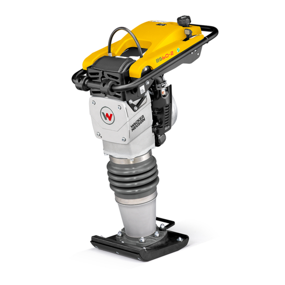
BS 60-2 / BS 70-2 Machine Description and Intended Use This machine is a vibratory rammer. The Wacker Neuson Rammer consists of a gasoline or diesel engine, a clutch, a fuel tank, a spring- loaded ramming system, a ramming shoe, and a handle. The engine transmits power through the ramming system and ramming shoe, generating percussive impact force to compact soil. -
Page 11: Safety Guidelines For Operating The Machine
BS 60-2 / BS 70-2 Safety Information Safety Guidelines for Operating the Machine Familiarity and proper training are required for the safe operation of the machine. Machines operated improperly or by untrained personnel can be hazardous. Read the operating instructions contained in this... - Page 12 Safety Information BS 60-2 / BS 70-2 1.3.10 Make sure that all other persons are at a safe distance from the machine. Stop the machine if people step into the working area of the machine. 1.3.11 Be sure operator is familiar with proper safety precautions and operation techniques before using machine.
-
Page 13: Operator Safety While Using Internal Combustion Engines
BS 60-2 / BS 70-2 Safety Information Operator Safety while Using Internal Combustion Engines WARNING Internal combustion engines present special hazards during operation and fueling. Failure to follow the warnings and safety standards could result in severe injury or death. -
Page 14: Service Safety
• Only trained personnel shall troubleshoot or repair problems occurring with the machine. • Contact Wacker Neuson for additional training if necessary. When servicing or maintaining this machine: • Do not allow improperly trained people to service or maintain the machine. - Page 15 1.5.11 ALWAYS clean debris from engine cooling fins. 1.5.12 When replacement parts are required for this machine, use only Wacker Neuson replacement parts or those parts equivalent to the original in all types of specifications, such as physical dimensions, type, strength, and material.
-
Page 16: Labels
Labels BS 60-2 / BS 70-2 Labels Label Locations wc_si000475gb.fm... -
Page 17: Label Meanings
BS 60-2 / BS 70-2 Labels Label Meanings Ref. Label Meaning To start the machine: 1. Move the throttle to the IDLE position. 2. Push the purge bulb 10 times. 3. Close the choke. 4. Pull the starter rope until engine starts. - Page 18 Labels BS 60-2 / BS 70-2 Ref. Label Meaning Warning! Springs are compressed. Release cover slowly to avoid spring ejection. See the Repair Manual for proper disassembly instructions. Move lever forward to stop machine. Move lever backward to run machine.
- Page 19 BS 60-2 / BS 70-2 Labels Ref. Label Meaning Guaranteed sound power level in dB(A). The air intake system is equipped with a filter indicator, which indicates when a filter change is required. Replace main paper filter element when yellow plunger of the indicator appears in or near the red line.
- Page 20 This rammer engine requires a two-cycle gasoline/oil mixture (50:1) With standard two-cycle oil use 50:1 ratio. With Wacker Neuson Neuson two-cycle or other oil meeting the NMMA TC-W3 specification, a ratio from 50:1 to 100:1 can be used. This label is molded into the cover. If the label becomes illegible, the cover must be replaced.
-
Page 21: Lifting And Transporting
BS 60-2 / BS 70-2 Lifting and Transporting Lifting and Transporting Lifting and Transporting See Graphic: wc_gr007405 3.1.1 Always shut off the engine and close the fuel valve when transporting the machine. 3.1.2 Make sure the lifting device has enough capacity to hold the machine (see identification plate on the machine for weight). - Page 22 Lifting and Transporting BS 60-2 / BS 70-2 Notes wc_tx001479gb.fm...
-
Page 23: Operation
4.1.2 Check the machine and its components for damage. If there is visible damage, do not operate the machine! Contact your Wacker Neuson dealer immediately for assistance. 4.1.3 Take inventory of all items included with the machine and verify that all loose components and fasteners are accounted for. -
Page 24: Recommended Fuel
This rammer engine requires a two-cycle gasoline/oil mixture. With standard two-cycle oil use 50:1 ratio. With Wacker Neuson two-cycle or other oil meeting the NMMA TC-W3 specification, a ratio from 50:1 to 100:1 can be used. Mix regular unleaded gasoline and two-cycle/outboard motor oil in separate container before filling tank. -
Page 25: Position Of The Operator
BS 60-2 / BS 70-2 Operation Position of the Operator For optimal control, performance, and minimal hand/arm vibration follow the guidelines below when using the machine. • Grasp the handle with both hands as shown. Hand/Arm Vibration (HAV) has been opti- mized for the hand position shown. -
Page 26: Before Starting
Operation BS 60-2 / BS 70-2 Before Starting 4.4.1 Read safety instructions at the beginning of this manual. 4.4.2 Fill tank with proper fuel mixture. 4.4.3 Place rammer on loose soil or gravel. DO NOT start rammer on hard surfaces such as asphalt or concrete. -
Page 27: Stopping
BS 60-2 / BS 70-2 Operation Stopping See Graphic: wc_gr007362 4.6.1 Place throttle in the idle position (c2). 4.6.2 Shut off the engine by moving the throttle through the detent to the off position (c1). The engine will stop and the fuel valve will close. -
Page 28: Maintenance
WACKER NEUSON. The use of service parts that are not equivalent in performance and durability to authorized parts may impair the effectiveness of the emission control system and may have a bearing on the outcome of a warranty claim. -
Page 29: Periodic Maintenance Schedule
BS 60-2 / BS 70-2 Maintenance Periodic Maintenance Schedule The table below lists basic machine maintenance. Tasks designated with check marks may be performed by the operator. Tasks designated with square bullet points require special training and equipment. After Every... -
Page 30: Servicing The Air Cleaner
Maintenance BS 60-2 / BS 70-2 Servicing the Air Cleaner See Graphic: wc_gr001168 NEVER use gasoline or other types of low flash point solvents for cleaning the air filter. A fire or explosion could result. WARNING NOTICE: NEVER run engine without main paper filter element (b). - Page 31 BS 60-2 / BS 70-2 Maintenance wc_gr001168 wc_tx000926gb.fm...
-
Page 32: Checking And Changing The Ramming System Oil
Maintenance BS 60-2 / BS 70-2 Checking and Changing the Ramming System Oil Background Lubricating oil is distributed throughout the ramming system by the action of the rammer. Holes drilled in the piston carry oil from the bottom of the rammer to the crankcase as the rammer operates. Oil in the ramming system must be maintained at the correct level to ensure the ramming system operates efficiently. - Page 33 BS 60-2 / BS 70-2 Maintenance 5.4.4 Remove the sightglass. Clean the threads of the sightglass, then wrap the threads with Teflon tape. 5.4.5 Add oil to the machine through the sightglass opening in the housing. 5.4.6 Stand the machine upright to check the oil level. Add enough oil so that when the machine is upright, oil will fill 1/2 to 3/4 of the sightglass.
-
Page 34: Shoe Hardware
Maintenance BS 60-2 / BS 70-2 Shoe Hardware See Graphic: wc_gr005384 On new machines, or after replacing shoe, check and tighten shoe hardware after the first 5 hours of operation. Inspect hardware every week thereafter. Torque hardware as specified. Cast Iron Shoe... -
Page 35: Adjusting The Idle Speed
BS 60-2 / BS 70-2 Maintenance Adjusting the idle speed See Graphic: wc_gr007402 Refer to Technical Data for correct idle and operating rpm. For best accuracy, use a tachometer when making idle speed adjustments. 5.6.1 Remove the guard (c). 5.6.2 Start the engine and allow it to warm up to operating temperature. -
Page 36: Long-Term Storage
Maintenance BS 60-2 / BS 70-2 Long-Term Storage Introduction Extended storage of equipment requires preventative maintenance. Performing these steps helps to preserve machine components and ensures the machine will be ready for future use. While not all of these steps necessarily apply to this machine, the basic procedures remain the same. - Page 37 BS 60-2 / BS 70-2 Maintenance Storing the machine Perform these remaining steps to store your machine. • Wash the machine and allow it to dry. • Move the machine to a clean, dry, secure storage location. Block or chock wheels to prevent machine movement.
-
Page 38: Basic Troubleshooting
Basic Troubleshooting BS 60-2 / BS 70-2 Basic Troubleshooting Problem / Symptom Reason / Remedy Engine does not start, or • No fuel in tank. stalls. • Spark plug fouled. Engine does not accelerate, is • Improper fuel mix. Too much oil. -
Page 39: Technical Data
BS 60-2 / BS 70-2 Technical Data Technical Data Rammer Engine Power Rating Net power rating per 80/1269/EEC and ISO 3046-1. Actual power output may vary due to conditions of specific use. Item Number: BS 60-2 BS 70-2 0009417 0009424... -
Page 40: Sound Measurements
Directive 2000/14/EC - Noise Emission in the Environment by Equipment for use outdoors. • the sound pressure level at operator's location (L BS 60-2, BS 60-2i = 98 dB(A) BS 70-2, BS 70-2i = 92 dB(A) • the guaranteed sound power level (L ) = 108 dB(A). -
Page 41: Dimensions
BS 60-2 / BS 70-2 Technical Data Dimensions 機械 管理番号 mm (in.) mm (in.) 0620905 280 (11.02) 336 (13.25) BS 60-2 0620907 330 (12.99) 342 (13.45) BS 70-2 wc_td000286gb.fm... - Page 42 Technical Data BS 60-2 / BS 70-2 wc_td000286gb.fm...
-
Page 43: Emission Control Systems Information And Warranty
Carbon monoxide does not react in the same way, but it is toxic. Wacker Neuson utilizes lean carburetor settings and other systems to reduce the emissions of carbon monoxide, oxides of nitrogen, and hydrocarbons. Evaporative Emissions... -
Page 44: Limited Defect Warranty For Wacker Neuson Emission Control Systems
Tampering and Altering Tampering with or altering the emission control system may increase emissions beyond the legal limit. If evidence of tampering is found, Wacker Neuson may deny a warranty claim. Among those acts that constitute tampering are: Removing or altering of any part of the air intake, fuel, or exhaust systems. - Page 45 Emission Control Systems Information and Warranty applicable EPA regulations. All defective parts replaced under this warranty become property of Wacker Neuson. Exhaust Emissions Systems Covered Components Fuel metering system Carburetor and internal parts Air/fuel ratio feedback system (if applicable) Cold start enrichment system...
- Page 46 The engine/equipment must be presented to an authorized Wacker Neuson dealer/ service center as soon as a problem exists. Contact Wacker Neuson Product Support Department (1-800-770-0957) or visit wackerneuson.com to find a dealer/ service center in your area, or to answer questions regarding warranty rights and responsibilities.
- Page 47 For owners located more than 100 miles from an authorized dealer/service center (excluding the states with high-altitude areas as identified in 40 CFR Part 1068, Appendix III), Wacker Neuson will pay for pre-approved shipping costs to and from an authorized Wacker Neuson dealer/service center.
- Page 50 Tel. : (262) 255-0500 Fax: (262) 255-0550 Tel.: (800) 770-0957 Wacker Neuson Limited - Room 1701–03 & 1717–20, 17/F. Tower 1, Grand Century Place, 193 Prince Edward Road West, Mongkok, Kowloon, Hongkong. Tel: (852) 3605 5360, Fax: (852) 2758 0032...
Need help?
Do you have a question about the BS 60-2 and is the answer not in the manual?
Questions and answers