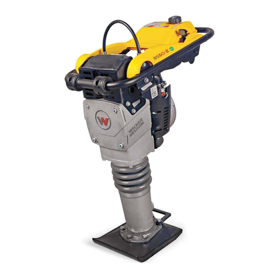
Wacker Neuson BS 50-2 Operator's Manual
Rammer
Hide thumbs
Also See for BS 50-2:
- Operator's manual (56 pages) ,
- Repair manual (194 pages) ,
- Operator's manual (42 pages)

Related Manuals for Wacker Neuson BS 50-2


Summary of Contents for Wacker Neuson BS 50-2
- Page 1 0158433en 1106 Rammer BS 50-2 OPERATOR’S MANUAL...
-
Page 3: Table Of Contents
BS 50-2 Table of Contents Foreword Emission Control System Information Safety Information Operating Safety ................11 Operator Safety while using Internal Combustion Engines ....12 Service Safety ..................13 Label Locations .................. 14 Safety Labels ..................15 Operating Labels ................18 Technical Data Rammer .................... - Page 4 Table of Contents BS 50-2 Maintenance Periodic Maintenance Schedule ............26 Servicing Air Cleaner ................27 Lubrication ...................28 Fuel Lines ....................29 Shoe Hardware ...................30 Carburetor Adjustments ..............30 Long-Term Storage ................31 Transportation ..................31 Troubleshooting ...................32 wc_bo0158433en_003TOC.fm...
-
Page 5: Foreword
CALIFORNIA Proposition 65 Warning: Engine exhaust, some of its constituents, and certain vehicle components, contain or emit chemicals known to the State of WARNING California to cause cancer and birth defects or other reproductive harm. Foreword This manual provides information and procedures to safely operate and maintain this Wacker model. -
Page 6: Emission Control System Information
Emission Control System Information Emission Control System Information Source of Emissions The combustion process produces carbon monoxide, oxides of nitrogen, and hydrocarbons. Control of hydrocarbons and oxides of nitrogen is very important because, under certain conditions, they react to form photochemical smog when subjected to sunlight. Carbon monoxide does not react in the same way, but it is toxic. - Page 7 Emission Control System Information Replacement Parts The emission control systems on your Wacker engine were designed, built, and certified to conform with EPA and California emissions regulations. We recommend the use of genuine Wacker parts whenever you have maintenance done. These original-design replacement parts are manufactured to the same standards as the original parts, so you can be confident of their performance.
- Page 8 Emission Control System Information METHANOL - (methyl or wood alcohol) 5% by volume. You may use gasoline containing up to 5% methanol by volume, as long as it contains cosolvents and corrosion inhibitors to protect the fuel system. Gasoline containing more than 5% methanol by volume may cause starting and/or performance problems.
- Page 9 Emission Control System Information OWNER’S WARRANTY RESPONSIBILITY: As the engine owner, you are responsible for the performance of the required maintenance listed in your owner’s manual. Wacker recommends that you retain all receipts covering maintenance on your engine, but Wacker cannot deny warranty coverage solely for the lack of receipts or for your failure to ensure the performance of all scheduled maintenance.
- Page 10 Emission Control System Information TO OBTAIN WARRANTY SERVICE: You must take your Wacker product along with proof of original purchase date, at your expense, to any Wacker authorized dealer during their normal business hours. Claims for repair or adjustment found to be caused solely by defects in material or workmanship will not be denied because the engine was not properly maintained and used.
- Page 11 Emission Control System Information SYSTEMS COVERED PARTS BY THIS WARRANTY DESCRIPTIONS FUEL METERING CARBURETOR ASSEMBLY EXHAUST SYSTEM MUFFLER AIR INDUCTION AIR FILTER HOUSING AIR FILTER ELEMENT* IGNITION FLYWHEEL MAGNETO IGNITION MODULE SPARK PLUG CAP SPARK PLUG* MISCELLANEOUS TUBING, FITTINGS, SEALS, GASKETS PARTS AND CLAMPS ASSOCIATED WITH THESE LISTED ITEMS...
-
Page 12: Safety Information
Safety Information BS 50-2 Safety Information This manual contains DANGER, WARNING, CAUTION, and NOTE callouts which must be followed to reduce the possibility of personal injury, damage to the equipment, or improper service. This is the safety alert symbol. It is used to alert you to potential personal injury hazards. -
Page 13: Operating Safety
BS 50-2 Safety Information Operating Safety Familiarity and proper training are required for the safe operation of equipment. Equipment operated improperly or by untrained personnel can be dangerous. Read the operating instructions contained in both WARNING this manual and the engine manual and familiarize yourself with the location and proper use of all controls. -
Page 14: Operator Safety While Using Internal Combustion Engines
Safety Information BS 50-2 3.1.18 ALWAYS guide the rammer in such a way that the operator is not squeezed between the rammer and solid objects. Special care is required when working on uneven ground or when compacting coarse material. Make sure to stand firmly when operating the machine under such conditions. -
Page 15: Service Safety
BS 50-2 Safety Information Service Safety Poorly maintained equipment can become a safety hazard! In order for the equipment to operate safely and properly over a long period of time, periodic maintenance and occasional repairs are necessary. WARNING 3.3.1 DO NOT attempt to clean or service the machine while it is running. -
Page 16: Label Locations
Safety Information BS 50-2 Label Locations wc_si000119gb.fm... -
Page 17: Safety Labels
BS 50-2 Safety Information Safety Labels Wacker machines use international pictorial labels where needed. These labels are described below: Label Meaning This molded-in label contains important safety and operating information. If it becomes illegible, the cover must be replaced. Refer to the Parts Book for ordering information. - Page 18 Safety Information BS 50-2 Label Meaning CAUTION! Use only clean, filtered gasoline fuel. WARNING! To prevent hearing loss, wear hearing protection when operating this machine. WARNING! Hot surface! Replace guard! WARNING! Serious injury if struck by compressed spring or cover. If the spring system cover is removed improperly, the springs can eject.
- Page 19 BS 50-2 Safety Information Label Meaning Guaranteed sound power level in dB(A) The air intake system is equipped with a filter indicator, which indicates when a filter change is required. Replace main paper filter element when yellow plunger of the indicator appears in or near the red line.
-
Page 20: Operating Labels
Safety Information BS 50-2 Operating Labels Wacker machines use international pictorial labels where needed. These labels are described below: Label Meaning Close the choke. Place the throttle control lever in the “start” position. Pull the rewind starter. Open the choke. - Page 21 BS 50-2 Safety Information Label Meaning Throttle control lever: 0 = Stop Turtle = Start or Idle Rabbit = Full or Fast Engine stop button: Press to stop engine. Choke: 0 = Open l = Closed This rammer engine requires a two-cycle gasoline/oil mixture.
-
Page 22: Technical Data
Technical Data BS 50-2 Technical Data Rammer Item Number: BS 50-2 0009380, 0009382, 0009384, 0009410 0009411, 0009413, 0620025, 0620048 Rammer Engine Model type WM80 Engine Speed - full 4400 ± 100 Engine Speed - idle 1800 ± 100 Clutch Engagement 2500 ±... -
Page 23: Sound Measurements
BS 50-2 Technical Data Sound Measurements Products are tested for sound pressure level in accordance with EN ISO 11204. Sound power level is tested in accordance with European Directive 2000/14/EC - Noise Emission in the Environment by Equipment for use outdoors. -
Page 24: Operation
Operation BS 50-2 Operation Application Rammers are designed to compact loose soils and gravel to prevent settling and to provide a firm, solid base for the placement of footings, concrete slabs, foundations, and other structures. Recommended Fuel This rammer engine requires a two-cycle gasoline/oil mixture. -
Page 25: To Start
BS 50-2 Operation To Start See Graphic: wc_gr001461 5.4.1 Open throttle to full position (c4). This will automatically turn on the flow of fuel. 5.4.2 Close choke (b1). 5.4.3 Pull starter rope (a). Repeat until engine starts. Multiple pulls (typically less than 5 pulls) may be required to start an engine: •... -
Page 26: To Stop
Operation BS 50-2 To Stop See Graphic: wc_gr001461 5.5.1 Place throttle in the idle position (c2). 5.5.2 Shut off the engine by moving the throttle through the detent to the off position (c1). The engine will stop and the fuel valve will close. -
Page 27: Proper Compaction
BS 50-2 Operation Proper Compaction See Graphic: wc_gr000045 5.7.1 Run rammer at the full throttle position (a4) for maximum performance. 5.7.2 Guide rammer with its handle. Allow machine to pull itself forward. DO NOT try to over-power the machine. 5.7.3 For best compaction, the shoe must hit the ground flat (b), not on its toe or heel. -
Page 28: Periodic Maintenance Schedule
Maintenance BS 50-2 Maintenance Periodic Maintenance Schedule After Every Every Every Daily first week month 3 months Every before or 25 or 100 or 300 Year starting hours hours hours hours Check fuel level. Check air filter indicator. Replace as needed. -
Page 29: Servicing Air Cleaner
BS 50-2 Maintenance Servicing Air Cleaner See Graphic: wc_gr001168 NEVER use gasoline or other types of low flash point solvents for cleaning the air filter. A fire or explosion could result. WARNING CAUTION: NEVER run engine without main paper filter element (b). -
Page 30: Lubrication
Maintenance BS 50-2 Lubrication See Graphic: wc_gr01463 Ramming system Check oil level: 6.3.1 Place the rammer so it is resting on its shoe on a level surface. 6.3.2 Check the oil level through oil sightglass (d). Proper ramming system lubrication is indicated when approximately 1/2–3/4 of the sightglass is full. -
Page 31: Fuel Lines
BS 50-2 Maintenance Fuel Lines See Graphic: wc_gr0001493 ALWAYS follow instructions when disconnecting fuel lines. Failure to do so may result in fuel squirting from fuel system. CAUTION To disconnect fuel lines: 6.4.1 Shut off the engine by moving the throttle through the detent to the off position (a). -
Page 32: Shoe Hardware
Maintenance BS 50-2 Shoe Hardware See Graphic: wc_gr000048 On new machines, or after replacing shoe, check and tighten shoe hardware (a) after the first 5 hours of operation. Inspect hardware every week thereafter. Torque hardware as specified. 8 6 N m ( 6 3 f t . -
Page 33: Long-Term Storage
BS 50-2 Maintenance Long-Term Storage 6.7.1 Drain fuel from tank. 6.7.2 Start engine and run until remaining fuel is used. 6.7.3 Remove spark plug. Pour approximately 30 ml (1 oz.) of clean SAE 10W30 engine oil into cylinder through spark plug opening. -
Page 34: Troubleshooting
Maintenance BS 50-2 Troubleshooting Problem / Symptom Reason / Remedy Engine does not start, or • No fuel in tank. stalls. • Spark plug fouled. • Fuel valve closed. Engine does not accelerate, is • Improper fuel mix. Too much oil. - Page 35 Net installed power / absolute installierte Leistung / Potencia instalada neta / Puissance installée nette : BS 50-2, BS 50-2i 1,8 kW Has been sound tested per Directive 2000/14/EC / In Übereinstimmung mit Richtlinie 2000/14/EG bewertet worden ist / Ha sido ensayado en conformidad con la norma 2000/14/CE / A été...
- Page 36 Wacker Construction Equipment AG · Preußenstraße 41 · D-80809 München · Tel.: +49-(0)89-3 54 02 - 0 · Fax: +49 - (0)89-3 54 02-3 90 Wacker Corporation · P.O. Box 9007 · Menomonee Falls, WI 53052-9007 · Tel. : (262) 255-0500 · Fax: (262) 255-0550 · Tel. : (800) 770-0957 Wacker Asia Pacific Operations ·...
Need help?
Do you have a question about the BS 50-2 and is the answer not in the manual?
Questions and answers