
Related Manuals for Advantech LGA 1700


Summary of Contents for Advantech LGA 1700
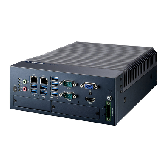
- Page 1 User Manual MIC-770 V3 Compact Fanless System with ® 12th Gen Intel Core™ i CPU Socket (LGA 1700)
- Page 2 No part of this manual may be reproduced, copied, translated, or transmitted in any form or by any means without the prior written permission of Advantech Co., Ltd. The information provided in this manual is intended to be accurate and reliable.
- Page 3 Product Warranty (2 years) Advantech warrants the original purchaser that each of its products will be free from defects in materials and workmanship for two years from the date of purchase. This warranty does not apply to any products that have been repaired or altered by persons other than repair personnel authorized by Advantech, or products that have been subject to misuse, abuse, accident, or improper installation.
- Page 4 Discard used batteries according to the manufacturer's instructions. Technical Support and Assistance Visit the Advantech website at http://support.advantech.com to obtain the latest product information. Contact your distributor, sales representative, or Advantech's customer service center for technical support if you need additional assistance. Please have the following information ready before calling: –...
- Page 5 Warnings, Cautions, and Notes Warning! Warnings indicate conditions that if not observed can cause personal injury! Caution! Cautions are included to help prevent hardware damage and data losses. For example: “Batteries are at risk of exploding if incorrectly installed. Do not attempt to recharge, force open, or heat the battery.
- Page 6 RESTRICTED ACCESS AREA: The equipment should only be installed in a Restricted Access Area. DISCLAIMER: These instructions are provided according to IEC 704-1 standards. Advantech disclaims all responsibility for the accuracy of any statements contained herein. MIC-770 V3 User Manual...
- Page 7 Safety Precautions Warning! Always completely disconnect the power cord from your chassis when- ever you work with the hardware. Do not make connections while the power is on. Sensitive electronic components can be damaged by sud- den power surges. Only experienced electronics personnel should open the PC chassis.
- Page 8 Ordering Information 2.5'' Part NVMe USB3.2 USB 3.2 PCIe/PCI VGA HDMI mSATA USB 2.0 GbE COM Power Number (Gen2) (Gen1) Exp. /SSD MIC- 9~36 2, up to 6 i-module 770V3W (Optional) (Optional) -00A1 MIC- 9~36 2, up to 6 i-module 770V3H- (Optional) (Optional)
- Page 9 98R17500210 MIC DIN-Rail Mounting kit (180) 98R17500501 MIC Wall Mount kit Supports i-Door module (MOS series), except PoE Please refer to the Advantech website below or search for "iDoor i-Door Module Module Mini PCIe Expansion Kit”. (MOS series module) http://www.advantech.com.tw/products/idoor-module-mini-pcie-...
- Page 10 i-module Optional Accessories Part Number Description 98R1751300E 1 x 8 cm FAN module (for MIC-75M13/75M40/75S20) 98R1752000E 2 x 4 cm FAN module (for MIC-75M20/MIC-75M11) MIC-770 V3 User Manual...
-
Page 11: Table Of Contents
Contents Chapter General Introduction ......1 Introduction ....................2 Product Features..................2 1.2.1 General ..................2 1.2.2 Display ..................2 1.2.3 Ethernet ..................3 1.2.4 SUSI API..................3 1.2.5 WISE-iBMC Out-of-Band Power Management ......3 Chipset ...................... 4 1.3.1 Functional Specifications .............. 4 Mechanical Specifications................. - Page 12 2.4.2 Memory Installation..............20 2.4.3 m-SATA/Mini-PCIe Installation ........... 21 2.4.4 Internal USB 2.0 Installation (R SKU only) ......... 22 2.4.5 COM 3/4/5/6 Port Installation............22 2.4.6 Expansion Module Installation (Optional) ........22 2.4.7 MIC-770 V3 MB I/O Connectors ..........23 Chapter BIOS Operation .........
- Page 13 Figure 3.46USB Configuration............ 67 Figure 3.47Security Configuration ..........68 Figure 3.48HD Audio Configuration..........69 3.2.4 Security ..................70 Figure 3.49Security..............70 3.2.5 Boot..................... 71 Figure 3.50Boot ................71 3.2.6 Save & Exit ................. 72 Figure 3.51Save & Exit ............... 72 Chapter Software Installation ......73...
- Page 14 Supported GPIO Register ............... 94 B.1.1 GPIO Registers................94 B.1.2 GPIO Example Program ............. 95 MIC-770 V3 User Manual...
-
Page 15: Chapter 1 General Introduction
Chapter General Introduction This chapter details background information on the MIC-770 V3. -
Page 16: Introduction
Introduction The Advantech MIC-770 V3 is a compact, fanless system that utilizes the latest gen- eration Intel® 14nm platform with the new PCH R680E/H610E on a proprietary form factor motherboard. The design concept of the Advantech MIC-770 V3 system focuses on an "expansion slot module", allowing for different applications to integrate the MIC-770 V3 system when developing a complete industrial computer. -
Page 17: Ethernet
LAN2 if abnormal conditions are selected. Note! The WISE-iBMC power control function is operated on Advantech WISE-DeviceOn software. Before installation and setup of the WISE- Agent program, changing the device IP address to the same as your network IP via a utility tool is necessary. -
Page 18: Chipset
Chipset 1.3.1 Functional Specifications 1.3.1.1 Processor ® Processor Intel 12th Gen Core i CPU socket (LGA1700) 1.3.1.2 Chipset ® Intel R680E/H610E chipset Supports DDR5 4800MHz MHz ECC RAM (R680E SKU only) (without ECC) Memory SODIMM Socket: – 260-pin SODIMM socket*2 (up to 32GB per socket) ®... - Page 19 1.3.1.3 Others Nuvoton NCT 6126D supported Up to 6 serial ports by Nuvoton NCT6126D supported. High-speed NS16C550A compatible UARTs with data rates up to 1.5 Mbps. Supports IRQ sharing among serial port . Serial ports COM1/2: Supports RS-232/422/485 and setting mode by BIOS and ...
-
Page 20: Mechanical Specifications
Mechanical Specifications 1.4.1 Dimensions UNIT : mm Figure 1.1 MIC-770 V3 Mechanical Dimensions 1.4.2 Weight 2.8 kg (6.17 lb) Power Requirements 1.5.1 System Power Minimum power input: DC12V (-25%) -30V (+20%), Absolute Maximum Ratings Voltage is 9V - 36V. 1.5.2 RTC Battery BR2032 3 V/190 mAh... -
Page 21: Environment Specification
Environment Specification 1.6.1 Operating Temperature -20 ~ 50 °C (4 ~ 122 °F) (65W CPU) & -20 ~ 60 °C (4 ~ 140 °F) (35W CPU) with 0.7m/sec airflow; with 1 x Industrial wide-temp SSD 1.6.2 System Safety Certification Test Temperature 0 ~ 40 °C with (32 ~ 104 °F) 2.5"... - Page 22 MIC-770 V3 User Manual...
-
Page 23: Chapter 2 H/W Installation
Chapter H/W Installation This chapter introduces external I/ O and the installation of MIC-770 V3 hardware. -
Page 24: Introduction
Introduction The following sections show the internal jumper settings and the external connectors and pin assignments. Jumpers & Slide Switches 2.2.1 Jumper Description You may configure the MIC-770 V3 to match the needs of your application by setting jumpers. A jumper is a metal bridge used to close an electric circuit. It consists of two metal pins and a small metal clip (often protected by a plastic cover) that slides over the pins to connect them. -
Page 25: Jumper List
2.2.2 Jumper List Table 2.1: Jumper List Label Function JCMOS1 Clear CMOS PSON1 System AT/ATX mode option JME1 ME jumper mode option JWDT1_JOBS1 Watchdog mode option 2.2.2.1 Clear CMOS The MIC-770 V3 single-board computer contains a jumper that can erase CMOS data and reset the system BIOS information. -
Page 26: Connectors
(4-5) ERR_BEEP 2.2.2.5 USB Standby Power & VGA Always-On Setting (DIP Switch) DIP Switch (SW1) Switch State Setting 1 (default) USB3C1 does not provide standby charging SW1-1 USB3C1 provides standby charging 2 (default) USB3C2 does not provide standby charging SW1-2 USB3C2 provides standby charging 3 (default) USB3C3 does not provide standby charging... - Page 27 2.3.1.1 COM Connector MIC-770 V3 provides two 9-pin D-sub connectors and offers RS-232/422/485 serial communication interface ports. The default setting is ES-232, but this can be modified in the BIOS settings. You can find detailed instructions in Chapter 3. Note! Expandable for four more optional RS-232 cables.
- Page 28 2.3.1.2 Ethernet Connector (LAN) MIC-770 V3 is equipped with two Ethernet controllers that are fully compliant with IEEE 802.3u 10/100/1000 Mbps CSMA/CD standards. LAN1 is equipped with Intel i219 and LAN2 is equipped with Intel i210. The Ethernet port provides a standard RJ- 45 jack connector with LED indicators on the front side to show its Active/Link status and Speed status.
- Page 29 2.3.1.4 USB 3.0 Connector MIC-770 V3 provides USB 3.2/3.1 interface connectors, which provide complete Plug & Play and hot swapping capabilities for up to 127 external devices. The USB inter- face complies with USB XHCI, Rev. 3.0. Please refer to the table below for pin assignments.
- Page 30 2.3.1.6 HDMI Connector An integrated 19-pin receptacle connector HDMI Type-A Interface is provided. The HDMI link supports resolutions of up to 4096 x 2160 @ 30Hz. Figure 2.6 HDMI Receptacle Connector Table 2.7: HDMI Connector Pin Assignments Signal Name Signal Name TMDS Data 2+ TMDS Data 2 shield TMDS Data 2-...
- Page 31 2.3.1.8 Power ON/OFF Button MIC-770 V3 comes with a Power On/Off button with LED indicators on the front side to show its On status (Green LED) and Off/Suspend status (RED LED). It supports dual functions of Soft Power-On/Off (instant off or delay 4 seconds), and suspend. Power button LED status: System On: LED On System Suspend: Fast flashes...
-
Page 32: Installation
Installation 2.4.1 HDD Installation Undo the 4 screws and remove the bottom cover. Undo the 4 screws to remove the HDD tray. MIC-770 V3 User Manual... - Page 33 Secure the HDD with 4 x HDD screws (P/N:1930002235). Assemble the SATA cable/power cable and replace the HDD tray; secure with 4 screws. Replace the bottom cover. Note! Please refer to the i-Module Manual for i-module assembly. MIC-770 V3 User Manual...
- Page 34 2.4.2 Memory Installation Undo the 4 screws to remove the bottom cover. Undo the 7 screws to remove the memory thermal cover and install the memory and affix the thermal pad (P/N: 1990019498N000). MIC-770 V3 User Manual...
- Page 35 Undo the 3 screws to remove the memory thermal cover. Affix the thermal pad (P/N: 1990019498N000) to the memory and reassemble the memory. Note! The thermal pad and memory thermal cover must be completely cov- ered and secured. 2.4.3 m-SATA/Mini-PCIe Installation R680E: 1 x Mini PCIe (via Nano-SIM), 1 x Mini PCIe / mSATA ...
- Page 36 2.4.4 Internal USB 2.0 Installation (R SKU only) Undo the 4 x screws and remove the bottom cover. Loosen the screws and adjust the bracket size in accordance with the USB don- gle size. Replace the bottom cover and secure with screws. 2.4.5 COM 3/4/5/6 Port Installation MIC-770 V3 supports 2 x standard RS-232/422/485 serial ports.
- Page 37 Remove the baffle cover. Assemble the module on the motherboard (Note: Optional expansion modules need to be connected with a cable. (Please refer to MB internal I/O connector specifications on the I/O connector page for GPIO connectors.) Assemble the module baffle with screws. Replace the bottom cover and secure with screws.
- Page 38 MIC-770 V3 User Manual...
- Page 39 Chapter BIOS Operation...
- Page 40 Introduction With the AMI BIOS Setup Utility, you can modify BIOS settings and control the spe- cific features of your computer. The Setup Utility uses a number of menus for making changes and turning the specific features on or off. This chapter describes the basic navigation of the MIC-770 V3 setup screens.
- Page 41 Entering BIOS Setup Press <Del> at bootup to enter the AMI BIOS Setup Utility. The Main Menu will appear on the screen. Use the arrow keys to select among the items and press <Enter> to accept or enter the sub-menu. The Main BIOS setup screen has two main frames.
- Page 42 3.2.2 Advanced BIOS Features Setup Select the Advanced tab from the MIC-770 V3 setup screen to enter the Advanced BIOS setup screen. You can select any of the items in the left frame of the screen, such as CPU configuration, to go to the sub-menu for that item. You can display an Advanced BIOS setup option by highlighting it using the <Arrow>...
- Page 43 3.2.2.1 iBMC Configuration Figure 3.4 iBMC Configuration iBMC "Enable" or "Disable" the iBMC controller’s hardware communication. The default setting is "Enabled". The iBMC controller/function can be disabled if the item is selected as "Disabled". MIC-770 V3 User Manual...
- Page 44 3.2.2.2 Platform Misc Configuration Figure 3.5 Platform Misc Configuration Native PCIE Enable "Enable" or "Disable" PCI Express native support. MIC-770 V3 User Manual...
- Page 45 3.2.2.3 CPU Configuration Figure 3.6 CPU Configuration Software Guard Extensions (SGX) ® "Enable" or "Disable" software control of Intel Software Guard Extensions. MIC-770 V3 User Manual...
- Page 46 Hardware Prefetcher Hardware Prefetcher is a technique that fetches instructions and/or data from memory into the CPU cache memory well before the CPU needs it to improve the load-to-use latency. You may choose to "Enable" or "Disable" it. Adjacent Cache Line Prefetch ...
- Page 47 3.2.2.4 Power & Performance Figure 3.7 Power & Performance Figure 3.8 CPU - Power Management Control Power Config Default is Max. TDP which enables the user to adjust CPU TDP to 35W or 15W according to the user's requirements. MIC-770 V3 User Manual...
- Page 48 Boot Performance Select the performance state that the BIOS will set before OS handoff. ® Intel Speedstep™ Allows more than two frequency ranges to be supported. Turbo Mode "Enable" or "Disable" processor turbo mode. C states ®...
- Page 49 AMT Configuration Figure 3.10 AMT Configuration CIRA Configuration Figure 3.11 CIRA Configuration – Activate Remote Assistance Process Trigger CIRA boot. MIC-770 V3 User Manual...
- Page 50 ASF Configuration Figure 3.12 ASF Configuration – PET Progress "Enable" or "Disable" PET events Progress to receive PET events. – WatchDog “Enable" or "Disable” Watchdog Timer. – ASF Sensors Table "Enable" or "Disable" to add ASF Sensor Table into the ASF ACPI Table. MIC-770 V3 User Manual...
- Page 51 Secure Erase Configuration Figure 3.13 Secure Erase Configuration – Secure Erase mode Change Secure Erase module behavior as "Simulated" or "Real". – Force Secure Erase "Enable" or "Disable" force Secure Erase on next boot. MIC-770 V3 User Manual...
- Page 52 OEM Flag Settings Figure 3.14 OEM Flag Settings – MEBx hotkey Pressed "Enable" or "Disable" automatic MEBx hotkey press. – MEBx Selection Screen "Enable" or "Disable" MEBx Selection Screen. – Hide Un-Configure ME Confirmation Prompt Hide Un-Configure ME without password confirmation prompt. –...
- Page 53 MEBx Resolution Settings Figure 3.15 MEBx Resolution Settings – Non-UI Mode Resolution Set resolution for non-UI text mode. – UI Mode Resolution Set resolution for UI text mode. – Graphics Mode Resolution Set resolution for graphics mode. MIC-770 V3 User Manual...
- Page 54 Firmware Update Configuration Figure 3.16 Firmware Update Configuration – ME FW Image Re-flash "Enable" or "Disable" ME firmware image re-flash function. MIC-770 V3 User Manual...
- Page 55 3.2.2.6 Trusted Computing Figure 3.17 TPM Settings TPM Support "Enable" or "Disable" TPM Support. You can purchase Advantech the LPC TPM module to enable the TPM function. P/N: PCA-TPM-00B1E. MIC-770 V3 User Manual...
- Page 56 3.2.2.7 ACPI Settings Figure 3.18 ACPI Settings Enable ACPI Auto Configuration "Enable" or "Disable" ACPI auto configuration. Enable Hibernation "Enable" or "Disable" Hibernation (OS/S4 Sleep State). This option may not be applied in some OS. ACPI Sleep State ...
- Page 57 3.2.2.8 SMART Settings Figure 3.19 SMART Settings SMART Self Test "Enable" or "Disable" SMART Self Test on all HDDs during POST. MIC-770 V3 User Manual...
- Page 58 3.2.2.9 Super IO Configuration MIC-770 V3 supports 2 x RS-232/422/485 on the front side. MIC-770 has 4 more RS-232 (Serial Port 3, 4, 5, 6) via 2x DB9 cables in the accessory box. Figure 3.20 Super IO Configuration Figure 3.21 Serial Port 1 Configuration MIC-770 V3 User Manual...
- Page 59 Figure 3.22 Serial Port 2 Configuration Figure 3.23 Serial Port 3 Configuration MIC-770 V3 User Manual...
- Page 60 Figure 3.24 Serial Port 4 Configuration Figure 3.25 Serial Port 5 Configuration MIC-770 V3 User Manual...
- Page 61 Figure 3.26 Serial Port 6 Configuration Serial Port 1 Configuration – Serial Port "Enable" or "Disable" Serial Port 1. – Change Settings Select an optimal setting for serial port 1. Serial Port 2 Configuration – Serial Port "Enable" or "Disable" Serial Port 2. –...
- Page 62 3.2.2.10 H/W Monitor Figure 3.27 PC Health Status Case Open Warning "Enable" or "Disable" the Chassis Intrusion monitoring function. When it is enabled and the case is opened, the speaker beeps. CPU (PECI) Warning Temperature Use this item to set the CPU warning temperature. When the system reaches the warning temperature, the speaker will beep.
- Page 63 ACPI (PECI) Shutdown Temperature Use this item to set the ACPI shutdown temperature. When the system reaches the shutdown temperature, it will be automatically shut down by ACPI OS to pro- tect the system from overheating damage. Fan Configuration ...
- Page 64 MIC-770 V3 User Manual...
- Page 65 3.2.2.11 S5 RTC Wake Settings Figure 3.28 S5 RTC Wake Settings Wake system with Fixed Time "Enable" or "Disable" System wake on alarm event. The system will wake on the hr:min:sec as specified. MIC-770 V3 User Manual...
- Page 66 3.2.2.12 Serial Port Console Redirection Figure 3.29 Serial Port Console Redirection Figure 3.30 Legacy Console Redirection Settings COM1 – Console Redirection Settings Console Redirection "Enable" or "Disable". MIC-770 V3 User Manual...
- Page 67 Legacy Console Redirection – Legacy Console Redirection Settings Select a COM port to display redirection of Legacy OS and Legacy OPROM Messages. Serial Port for Out-of-Band Management/ Windows Emergency Manage- ment services (EMS) – Console Redirection Settings Console Redirection "Enable" or "Disable". ®...
- Page 68 3.2.2.14 USB Configuration Figure 3.32 USB Configuration Legacy USB Support This is for supporting USB devices under legacy OS such as DOS. When choosing "AUTO", the system will automatically detect if any USB device is plugged into the computer and enable USB legacy mode when a USB device is plugged in and disable USB legacy mode when no USB device is plugged in.
- Page 69 3.2.2.15 Network Stack Configuration Figure 3.33 Network Stack Configuration Network Stack "Enable" or "Disable" UEFI Network Stack. MIC-770 V3 User Manual...
- Page 70 3.2.2.16 CSM Configuration Figure 3.34 CSM Configuration Compatibility Support Module Configuration – CSM Support "Enable" or "Disable" CSM Support. The default setting is "Disabled". If your graphics card does not support UEFI mode, make sure to select "Enabled" to allow non-UEFI boot mode before installing the graphics card to turn on the computer.
- Page 71 3.2.2.17 NVMe Configuration Figure 3.35 NVMe Configuration NVMe Configuration NVMe M.2 storage device is supported. MIC-770 V3 User Manual...
- Page 72 3.2.3 Chipset Figure 3.36 Chipset This page provides information for the chipset on MIC-770 V3. MIC-770 V3 User Manual...
- Page 73 3.2.3.1 System Agent (SA) Configuration Figure 3.37 System Agent (SA) Configuration VT-d "Enable" or "Disable" the VT-d function. Above 4GB MMIO BIOS assignment "Enable" or "Disable" above 4GB Memory Mapped IO BIOS assignment. IPU Device (B0:D5:F0) "Enable" or "Disable" SA IPU device. MIC-770 V3 User Manual...
- Page 74 3.2.3.2 Memory Configuration Figure 3.38 Memory Configuration Maximum Memory Frequency Maximum memory frequency selections in MHz. MIC-770 V3 User Manual...
- Page 75 3.2.3.3 Graphics Configuration Figure 3.39 Graphics Configuration Primary Display Set Primary Display to "Auto", "IGFX", "PEG", "PCI", or "SG". Internal Graphics Set Internal Graphics to "Auto", "Disable", or "Enable". "Auto" will disable inter- nal graphics when a GPU card is installed. If GPU and internal graphics outputs are required at the same time, set this item to "Enable".
- Page 76 3.2.3.4 PEG Port Configuration Figure 3.40 PEG Port Configuration Figure 3.41 PEG Port Feature Configuration Enable Root Port "Enable" or "Disable" the root port. Max Link speed Configure PEG 0:1:0 max speed. MIC-770 V3 User Manual...
- Page 77 PEG Port Feature Configuration – Detect Non-Compliance Device Detect non-compliance PCI Express devices in PEG. If enabled, it will take more time during POST. 3.2.3.5 PCH-IO Configuration Figure 3.42 PCH-IO Configuration LAN1 Controller "Enable" or "Disable" the LAN1 controller. LAN1 Option-ROM ...
- Page 78 3.2.3.6 PCI Express Configuration Figure 3.43 PCI Express Configuration MIC-770 V3 User Manual...
- Page 79 Figure 3.44 PCI Express Root Port PCI Express Root Port 1 "Enable" or "Disable" PCI Express Root Port. PCIe Speed Select "Auto", "Gen1", "Gen2", or "Gen 3" for PCIe Speed. MIC-770 V3 User Manual...
- Page 80 3.2.3.7 SATA and RST Configuration Figure 3.45 SATA and RST Configuration SATA Controller(s) "Enable" or "Disable" the SATA controller. SATA Mode Selection This can be configured as "RAID" or "AHCI". Port 1~4 "Enable" or "Disable" SATA ports 1~4. Hot Plug ...
- Page 81 3.2.3.8 USB Configuration Figure 3.46 USB Configuration XHCI Compliance Mode Option to "Enable" or "Disable" XHCI compliance mode. The default is to disable compliance mode. MIC-770 V3 User Manual...
- Page 82 3.2.3.9 Security Configuration Figure 3.47 Security Configuration RTC Memory Lock "Enable" will lock bytes 38h-3Fh in the lower/upper 128-byte bank of RTC RAM. BIOS Lock "Enable" or "Disable" the PCH BIOS Lock Enable feature. It is required to be enabled to ensure SMM protection of flash.
- Page 83 3.2.3.10 HD Audio Configuration Figure 3.48 HD Audio Configuration HD Audio Control detection of the HD-Audio device. Disable = HDA will be unconditionally disabled. Enable=HDA will be unconditionally enabled. MIC-770 V3 User Manual...
-
Page 84: Security
3.2.4 Security Figure 3.49 Security Select Security Setup from the MIC-770 V3 Setup main BIOS setup menu. All Secu- rity Setup options, such as password protection are described in this section. To access the sub-menu for the following items, select the item and press <Enter>. Note! If only the User's password is set, the User will have Administrator rights. -
Page 85: Boot
3.2.5 Boot Figure 3.50 Boot Setup Prompt Timeout Directly key in the number, or use the <+> and <-> keys to adjust the number of seconds to wait for the setup activation key. Bootup NumLock State Default state for the NumLock key during power on. Quiet Boot ... -
Page 86: Save & Exit
3.2.6 Save & Exit Figure 3.51 Save & Exit Save Changes and Exit When you complete system configuration, select this option to save your changes, exit BIOS setup and reboot the computer so the new system configuration parame- ters can take effect. Select Exit Saving Changes from the Exit menu and press <Enter>. -
Page 87: Chapter 4 Software Installation
Chapter Software Installation This chapter covers driver installation. -
Page 88: Before You Begin
Windows 10 (64-bit) Windows Driver Setup Enter the Advantech support website, then search for MIC-770 V3. You can find the graphics drivers for MIC-770 V3 inside. MIC-770 V3 User Manual... -
Page 89: Chapter 5 Integrated Graphics Device Setup
Chapter Integrated Graphics Device Setup... -
Page 90: Introduction
Before installing this driver, make sure the INF driver has been installed in your system. See Chapter 4 for information on installing the INF driver. Enter the Advantech support website, then search for MIC-770 V3. You can find the "Graphics" driver inside. MIC-770 V3 User Manual... -
Page 91: Intel® Me
Chapter ® Intel... -
Page 92: Introduction
The installer detects the system's capabili- ties and installs the relevant drivers and applications. Installation Enter the Advantech support website, then search for MIC-770 V3. You can find the "ME" drivers there. MIC-770 V3 User Manual... -
Page 93: Chapter 7 Lan Configuration
Chapter LAN Configuration... -
Page 94: Introduction
In the following sections, refer to the one that provides the driver setup procedure for the operating system you are using. Windows Driver Setup Enter the Advantech support website, then search for MIC-770 V3. You can find the "LAN" driver inside. MIC-770 V3 User Manual... -
Page 95: Chapter 8 Sata Raid Setup
Chapter SATA RAID Setup... -
Page 96: Introduction
Each of the drives in the RAID 0 array is then mirrored by a RAID 1 component. SATA RAID Driver and Utility Setup Enter the Advantech support website, then search for MIC-770 V3. You can see the "Others" folder containing the RST driver. -
Page 97: Chapter 9 Hd Audio
Chapter HD Audio... -
Page 98: Introduction
MIC-770 V3 is equipped with a Realtek ALC888S audio chip. It provides "Line-out" & "Microphone" ports for diverse applications. Installation Enter the Advantech support website, then search for MIC-770 V3. This is where users can find the "Audio" drivers. MIC-770 V3 User Manual... -
Page 99: Appendix A Programming The Watchdog Timer
Appendix Programming the Watchdog Timer... -
Page 100: Programming The Watchdog Timer
Programming the Watchdog Timer The MIC-770 V3's watchdog timer can be used to monitor system software operation and take corrective action if the software fails to function within the programmed period. This section describes the operation of the watchdog timer and how to pro- gram it. - Page 101 Unlock NCT6126D Select register of watchdog timer Enable the function of the watchdog timer Use the function of the watchdog timer Lock NCT6126D MIC-770 V3 User Manual...
- Page 102 Table A.1: Watchdog Timer Registers Address of Register (2E) Attribute Read/Write Value (2F) & description 87 (hex) ----- Write this address to I/O address port 2E (hex) twice to unlock the NCT6126D. 07 (hex) write Write 08 (hex) to select register of watchdog timer. 30 (hex) write Write 01 (hex) to enable the function of the watch-...
-
Page 103: Example Program
A.1.3 Example Program Enable watchdog timer and set 10 sec. as timeout interval. ;----------------------------------------------------------- Mov dx,2eh ; Unlock NCT6126D Mov al,87h Out dx,al Out dx,al ;----------------------------------------------------------- Mov al,07h ; Select register of the watchdog timer. Out dx,al Inc dx Mov al,08h Out dx,al ;----------------------------------------------------------- Dec dx ;... - Page 104 ;----------------------------------------------------------- Mov al,07h ; Select register of the watchdog timer. Out dx,al Inc dx Mov al,08h Out dx,al ;----------------------------------------------------------- Dec dx ; Enable the function of watchdog timer. Mov al,30h Out dx,al Inc dx Mov al,01h Out dx,al ;----------------------------------------------------------- Dec dx ; Set minutes as the counting unit. Mov al,0f0h Out dx,al Inc dx...
- Page 105 Dec dx ; Enable the function of the watchdog timer. Mov al,30h Out dx,al Inc dx Mov al,01h Out dx,al ;----------------------------------------------------------- Dec dx ; Enable the watchdog timer to be reset by mouse. Mov al,0f2h Out dx,al Inc dx In al,dx Or al,80h Out dx,al ;-----------------------------------------------------------...
- Page 106 ;----------------------------------------------------------- Dec dx ; Lock NCT6126D Mov al,0aah Out dx,al Generate a time-out signal without timer counting. ;----------------------------------------------------------- Mov dx,2eh ; Unlock NCT6126D Mov al,87h Out dx,al Out dx,al ;----------------------------------------------------------- Mov al,07h ; Select register of the watchdog timer. Out dx,al Inc dx Mov al,08h Out dx,al...
-
Page 107: Appendix B Programming The Gpio
Appendix Programming the GPIO... - Page 108 Supported GPIO Register The following is a description of the GPIO addresses and programming sample. B.1.1 GPIO Registers GPIO 1 CRF0 (GP10-GP17 I/O selection register. Default 0xFF) When set to '1', the respective GPIO port is programmed as an input port. When set to '0', the respective GPIO port is programmed as an output port.
- Page 109 B.1.2 GPIO Example Program ------------------------------------------------------------ Enter the extended function mode, interruptible double-write ------------------------------------------------------------ MOV DX, 2EH MOV AL, 87H OUT DX, AL OUT DX, AL ------------------------------------------------------------ Configure logical device 7(GP10~GP17), configuration register CRE4,CRE5,CRE6 ------------------------------------------------------------ MOV DX, 2EH MOV AL, 07H ; Point to Logical Device Number Reg. OUT DX, AL MOV DX, 2FH MOV AL, 07H ;...
- Page 110 No part of this publication may be reproduced in any form or by any means, such as electronically, by photocopying, recording, or otherwise, without prior written permission from the publisher. All brand and product names are trademarks or registered trademarks of their respective companies. © Advantech Co., Ltd. 2023...
Need help?
Do you have a question about the LGA 1700 and is the answer not in the manual?
Questions and answers