Table of Contents
Advertisement
Quick Links
Advertisement
Table of Contents

Related Manuals for Vista PVM27CAM


Summary of Contents for Vista PVM27CAM
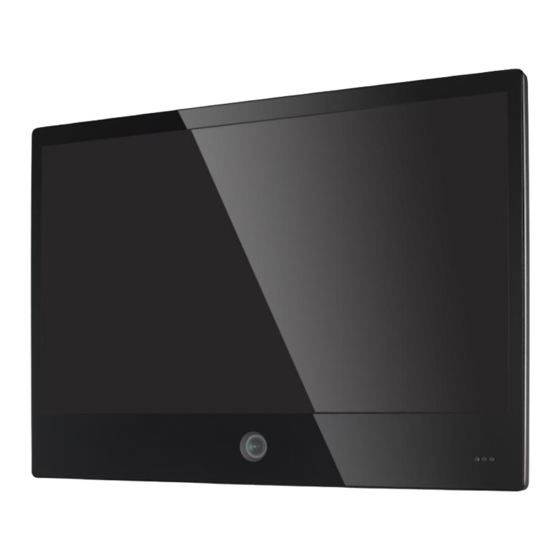
- Page 1 Installation and User Manual PVM27CAM...
-
Page 3: Table Of Contents
Contents CE INFORMATION ......................d SAFETY PRECAUTIONS ....................d BEFORE YOU BEGIN ....................e Scope ..........................1 Functional Specifications .................... 2 Power Supply ............................2 Video Characteristics ..........................2 VGA Input .............................. 2 Controls: Back Push Buttons ......................... 2 HDMI Input ............................2 Audio Input ............................ - Page 4 EN50130-4 ........................24 Reliability ........................25 Mean Time Between Failures (MTBF): ....................25 Mechanical ......................... 26 VESA mounting ........................... 27...
-
Page 5: Ce Information
CE INFORMATION The product must be installed according to the currently valid installation regulations for EMC to guarantee the designed use and to prevent EMC problems. The device supplied with this manual is according to the EC, EMC Directive, 2004/108/EC & LVD 2006/95/EC SAFETY PRECAUTIONS 1. -
Page 6: Before You Begin
If you still have questions, please contact Norbain Technical Support and Sales: Vista, 210 Wharfedale Road, IQ Winnersh, Wokingham, Berkshire RG41 5TP, England. UK +44 (0) 118 912 5000 Note: You... - Page 7 This apparatus is manufactured to comply with the radio interference. A Declaration of Conformity in accordance with the following EU standards has been made. The manufacturer declares that the product supplied with this document is compliant the provisions of the EMC Directive 2004/108/EC, the CE Marking Directive 93/68 EEC and all associated amendments All lead-free products offered by the company comply with the...
-
Page 8: Scope
Scope This document is used to define the performance of the LCD Public View Monitor (PVM) series. The system supports video and PC inputs, as well as from the built-in camera. In video mode, the display automatically detects NTSC and PAL signals. The On Screen Display (OSD) menu makes the system easy to operate. -
Page 9: Functional Specifications
Functional Specifications Power Supply 27” PVM Monitor Power Requirements: Voltage: 12Vdc or 24Vdc Current: 4 A max (12Vdc) or 2A max (24Vdc) Use only a PSU rated at 12dc, with a minimum current rating of 4A; or 24Vdc, with a minimum current rating of 2A Video Characteristics Composite Video (CVBS): 1.0Vp-p (0.5 –... -
Page 10: Environmental
Environmental Temperature: Operating: 0 C to +40 Storage: -20 C to +60 Humidity: Operating: 10% to 85% (non-condensing) Storage: 10% to 95% (non-condensing) EDID This series of displays support EDID. Controls and Indicators Connectors DC-In USB HDMI VGA Video-out ideo-in CAM-out Audio-in SD-card Power Video... -
Page 11: Camera Lens Adjust
Camera Lens Adjust W: Adjust Camera zoom to Wide. T: Adjust Camera zoom to Tele. N: Adjust Camera Focus to Near. F: Adjust Camera Focus to Far. -
Page 12: Remote Control
Remote Control Monitor and MMP Control: Power – Power On or Off the PVM monitor MUTE – Mute the audio CAM – Select Camera source VIDEO – Select Video source PC – Select VGA source HDMI – Select HDMI source MMP –... -
Page 13: Accessories
Accessories 1. 60 Watts 12V power adapter x1 2. UK Power Cord x1 3. EU Power Cord x1 4. Remote Control x1 5. DC Terminator x1 6. Cable Tie & Terminator x1 7. AAA battery x 2 8. User manual x 1... -
Page 14: Osd Menu
OSD Menu Hot key VOLUME:Press - / + buttons to adjust the volume. KEY LOCK:Press CHANNEL + MENU + POWER key for 6 sec to enable this function. KEY UN-LOCK:Press CHANNEL + MENU + POWER key for 6 sec to disable this function. -
Page 15: Main Menu
Main Menu Press Monitor MENU button to enter the sub-menu Main Adjust Color Adjust Scan Setting Image Adjust Information Language Setup Menu PVM Function Recall Audio Control Exit Press - /+ buttons to select an icon, then press MENU button to confirm the selection. -
Page 16: Main Adjust
MAIN ADJUST Press MENU button to enter the sub-menu 1. Press - / + buttons to select an icon 2. Press MENU button to confirm the selection. 3. Press - / + buttons to adjust the value 4. Press MENU button to return VIVID MODE Select Vivid mode BRIGHTNESS Adjust the brightness value CONTRAST Adjust the contrast value... -
Page 17: Color Adjust
COLOR ADJUST Press MENU button to enter the sub-menu 1. Press - / + buttons to select an icon 2. Press MENU button to confirm the selection. 3. Press - / + buttons to adjust the value 4. Press MENU button to return. COLOR TEMP Select Monitor color temperature USER/ 6500K / 7500K / 9300K RED: Adjust the RED value GREEN Adjust the GREEN value... -
Page 18: Scan Setting
SCAN SETTING Press MENU button to enter the sub-menu 1. Press - / + buttons to select an icon 2. Press MENU button to confirm the selection. 3. Press - / + buttons to adjust the value 4. Press MENU button to return. ASPECT RATIO Select aspect ratio 4:3 / 16:9 / AUTO IMAGE ADJUST (VGA ONLY) 1. -
Page 19: Information
3. Press - / + buttons to adjust the value 4. Press MENU button to return AUTO ADJUST Press MENU buttons to auto adjust Image Settings H. POSITION Adjust the horizontal position value V. POSITION Adjust the vertical position value PHASE Adjust the phase value CLOCK Adjust the clock value EXIT Press MENU button to return to the main menu... -
Page 20: Language
LANGUAGE Press MENU button to enter the sub-menu 1. Press - / + buttons to select an icon 2. Press MENU button to confirm the selection. 3. Press - / + buttons to adjust the value 4. Press MENU button to return. SETUP MENU Press MENU button to enter the sub-menu 1. -
Page 21: Pvm Function (Video Only)
3. Press - / + buttons to adjust the value 4. Press MENU button to return OSD TIMEOUT Adjust the OSD timeout OSD BLENDING Adjust the OSD blending BACKLIGHT SENSOR Adjust the backlight sensor LED FLASH LED FLASH 1sec(on)/1sec(off) - - OFF/ON LED SWAP Adjust LED color GREEN or RED FW. -
Page 22: Recall
DISPLAY MESSAGE Setting the warning message display (OFF / ON ). WARNING MESSAGE Setting the message text select (0~5, USER). The default message text 0-5 is: 0- RECORDING IN PROGRESS 1- RECORDING 2- WELCOME 3- CAMERA OPERATING 4- CAMERA ON DUTY 5- VIDEO SURVEILLANCE USER EDIT Left and Right to change the position, Up and Down to select the character, Menu to exit. - Page 23 1. Press UP / Down buttons to select an item. 2. Press Menu button to select adjust item. 3. Press Left / Right buttons to adjust the value. 4. Press Menu button to return. VOLUME Adjust the PVM Monitor volume. MUTE Select Audio MUTE.
-
Page 24: Multi Media Player Osd Menu
Multi Media Player OSD Menu The Multi Media Player (MMP) allows viewing of digital photo, music, movie and text from USB or SD card. It is operated by Remote Control The MMP software has five main components: • Digital Photo Playback—display digital photos. •... -
Page 25: Camera Osd Menu
CAMERA OSD Menu The Camera OSD is controlled by Remote Controller. The definition of Remote Controller is defined as below. REMOTE CONTROL Camera Control: 5. Press Menu button to enter to Camera OSD 6. Press Enter button to confirm the selection 7. - Page 26 OSD Menu Press the MENU button to display MENU. You can set the LENS, EXP -OSURE, BACKLIGHT, DAY&NIGHT, WHITE BALTMAGE, DNR, SPECIAL and SYSTEM to ensure the image quality. LENS According to the lens type, you can enter the submenuand setup the MODE to what you need.
- Page 27 1.BLACKLIGHT-HLC Press the MENU button into the HLC submenu, can adjust HLC’s level and MODE. 2.BLACKLIGHT-BLC Press the MENU button into the BLC submenu, can adjust BLC area’s position and size. 3.BLACKLIGHT-WDR Press the MENU button into the WDR submenu, can adjust WDR MODE to: HIGH, MIDDLE and LOW.
- Page 28 IMAGE: Press the MENU button into the IMAGE submenu, can adjust SHARPN -ESS, BAMMA, COLOR GAIN, MIRROR, FLIP as needed SPECIAL Press the MENU button into the SPECIAL submenu. You can adjust D-ZOOM, ACE (D-WDR), DEFOG, SHADING, PRIVACY, and INTELLIGENT to ensure the image quality. DEFOG Setup the DEFOG MODE to AUTO or MANUAL, also can adjust the LEVEL to MIDDLE, HIGH or low as needed.
- Page 30 SYSTEM: Press the MENU button into the SYSTEM submenu, set the CAMERA ID, SYSTEM, LANGUAGE, RESET as needed.
-
Page 31: Regulatory Agency
Regulatory Agency Safety Approvals This series design shall meet the standards of the following domestic and foreign agencies: CE LVD : EN60950-1 EMI/EMS Emission Approvals This series design shall meet following EMI/EMS specifications: CE COMPLIANCE: EN55022 Class B. EN55024. EN50130-4... -
Page 32: Reliability
Reliability Mean Time Between Failures (MTBF): MTBF shall be 30,000 hours minimum at 90% confidence level and 100% duty cycle continuous operation at 25 C. The calculation does not include LCD panel. -
Page 33: Mechanical
Mechanical Cabinet Material: Metal. Finish: Black Dimensions Net Weight: 7.95Kg /17.49 lb, Shipping Weight: 10.5Kg / 23.1lb Packing material: Carton and EPE. -
Page 34: Vesa Mounting
VESA mounting Model VESA Length of screw PVM27CAM 100x100 mm M4 x 10mm 200x100 mm Use only M4 x 10mm screws to mount VESA bracket, failure to do so may cause serious injury. Ensure that the VESA bracket has an adequate size mounting plate, screws and/or fixings to support the weight of the monitor and bracket to the surface to which it is being attached. - Page 35 Norbain SD Ltd 210 Wharfedale Road IQ Winnersh Wokingham Berkshire RG41 5TP PVM27CAM Manual V1.0...
Need help?
Do you have a question about the PVM27CAM and is the answer not in the manual?
Questions and answers