Table of Contents
Advertisement
Quick Links
Advertisement
Table of Contents

Subscribe to Our Youtube Channel
Related Manuals for Vista PVM32CAMLV


Summary of Contents for Vista PVM32CAMLV
- Page 1 PVM32CAMLV Quick Guide Ver 1.0 IOT 2024-03-XX...
-
Page 2: Table Of Contents
Contents Before You Begin ......................2 Packing List ......................3 Safety & Maintenance Instructions ................3 Indicators and Interfaces..................4 Connecting PVM Monitor ..................5 Initial Setup ......................6 IOT Product Activation ..................... 6 IP Network Activation ....................9 Other Settings......................10 Set Time, Date and Network Settings .............. -
Page 3: Before You Begin
CCTV, IT and electrical wiring and products. Technical Support If you still have questions after referring to the guide, or require more information, please contact Vista Technical Support or use the QR code. Vista Technical Support +44 (0) 118 912 5125... -
Page 4: Packing List
Packing List Please contact Norbain if any items are missing or damaged. ➢ PVM Monitor ➢ Remote Control ➢ PSU adapter 100-240VAC to 24VDC 2.71A Safety & Maintenance Instructions • Use only the PSU supplied with the device or one of an identical rating. •... -
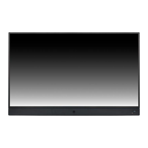
Page 5: Indicators And Interfaces
Indicators and Interfaces Refer below for description of indicators and interfaces. FRONT VIEW Name Function Camera Camera Lens White LED Configurable as an alert/deterrent Blue LED Indicates Power On (configurable on | off) Remote IR Remote Control Receiver TOP REAR VIEW Name Function DC IN... -
Page 6: Connecting Pvm Monitor
M4x8L (4PCS) VESA 100x100 and VESA 200x100 Rear view Connecting PVM Monitor Refer to the previous section and images for VESA dimensions as well as external interface connections and carryout the below. Determine your VESA mounting requirements – whether wall-mounted or pole. Fix the bracket or pole according to the relevant manufacturer’s instructions ensuring adequate fixings are used for the surface being fixed to and the load. -
Page 7: Initial Setup
Initial Setup If your PVM displays the IOT Security I O T S e c u r i t y screen (right) when first powering up, it requires activation by first setting its admin P l e a s e f i r s t a c t i v a t e V i s t a P V M b y account with your own strong password s e t t i n g a s t r o n g a d m i n p a s s w o r d . - Page 8 Note the requirements of a strong password on the screen below as you proceed! If activating via IP network and laptop, go to the IP Network Activation section instead. • Press [OK] button, the “Change Password” screen will be shown (below-right). C h a n g e P a s s w o r d I O T S e c u r i t y P l e a s e f i r s t a c t i v a t e V i s t a P V M b y...
- Page 9 • Once strong password is entered - pressing [MENU] moves cursor to the “Confirm Password” line. Re-enter the password and press [MENU] to complete. • If “Unsuccessful Password Entry!” screen is displayed – you mistyped the confirmation. Press [OK] to re-enter it, or [EXIT] to erase all passwords and start again.
-
Page 10: Ip Network Activation
First, install the Discovery Tool software to your laptop (below). • Visit url www.vista-cctv.com. • Click navigation bar and links Support > Downloads > Vista IP • Click folders [PVM10CAMxx Range] > [PVM10CAMS] > [Software] > [Discovery Tool] Click and download the latest version of the .zip file, unzip and install. -
Page 11: Other Settings
Other Settings Enter the PVMs menus to configure any required features or settings below. Use the remote control (right) and use the [menu] button, the arrow and [OK] buttons to navigate and select. CONFIGURABLE FEATURES • Date & Time • Network DHCP | static •... -
Page 12: Uploading Company Logo
• File size less than 1.5MB Click and follow the below link for detailed PVM Logo Upload instructions; Vista PVM10CAMx Logo Upload Password Recover Should you lose your password, simply use the remote control, press [MENU] and select [Restore Defaults]. Then Reactivate the PVM. - Page 13 No liability will be accepted by Vista for any errors or omissions in this information and reserves the right to make changes to the product and its specification from time to time...
- Page 14 Page intentionally left blank...
- Page 15 Page intentionally left blank...
- Page 16 Page intentionally left blank...
Need help?
Do you have a question about the PVM32CAMLV and is the answer not in the manual?
Questions and answers