Table of Contents
Advertisement
Quick Links
Advertisement
Table of Contents

Subscribe to Our Youtube Channel
Related Manuals for Vista PVM19CAM


Summary of Contents for Vista PVM19CAM
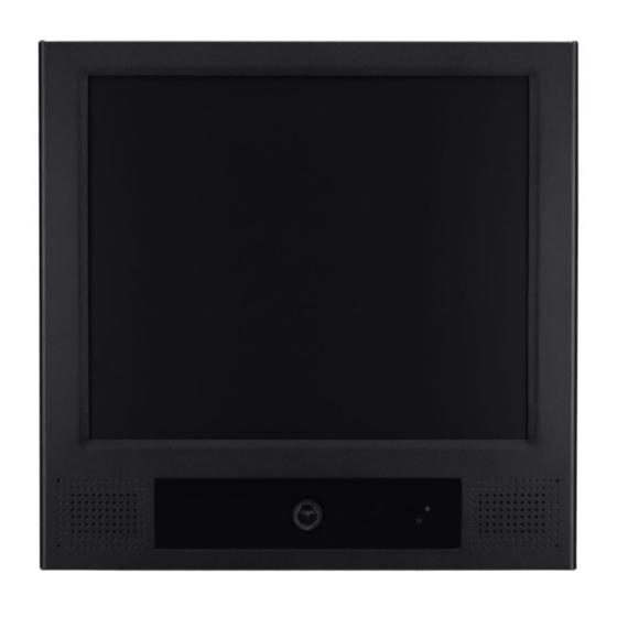
- Page 1 PVM19CAM Installation and User manual...
-
Page 3: Safety Precautions
CE INFORMATION The product must be installed according to the currently valid installation regulations for EMC to guarantee the designed use and to prevent EMC problems. The device supplied with this manual is according to the EC, EMC Directive 2004/108/EC, LVD 2006/95/EC and RoHS 201165/EU. SAFETY PRECAUTIONS 1. - Page 4 In order to meet immunity standards, the following cable lengths should not be exceeded without additional protection or electrical considerations: DC 24V in: 22m DC12 out: 3m HDMI: VGA: S-Video: 30m Audio In: 30m Note that cable length may depend on other factors such as other equipment or cable construction. This restriction is purely in respect of interference rejection, and that attaching long cables to these ports may act as antennae for high levels of interference which may affect performance of the product.
-
Page 5: Table Of Contents
Table of Contents Functional specification .................... 1 Power supply ......................1 Video Characteristics ....................1 VGA Input ........................1 Controls:Back Push Buttons ..................1 HDMI Input ........................1 Audio Input ......................... 1 Environmental ......................1 EDID ..........................1 Controls and indicators .................... 2 RemoteControl……………... - Page 6 Scope This specification is used to define the performance of PVM19CAM (LED Backlit monitors. This system supports both video input and PC inputs as well as built-in Camera video. In video input mode, the system can automatically detect PAL or NTSC signals. In PC mode, this system can support up to 1280 x 1204 VESA standard.
-
Page 7: Functional Specification
Functional Specifications Power Supply Monitor Power Requirements: Voltage: 12Vdc or 24Vdc Current: 4 A max (if 12Vdc) or 2A max (if 24Vdc) Use only a PSU rated at 12dc, with a minimum current rating of 4A; or 24Vdc, with a minimum current rating of 2A Video Characteristics Composite Video (CVBS): 1.0Vp-p (0.5 –... -
Page 8: Controls And Indicators
Controls and Indicators Connectors Power Video – DC 12V or 24V IN connector – HDMI - S-VIDEO (Y/C) IN: Mini-DIN 4 pins x1 – VGA – CAMERA OUT: BNC x1 – DC12V OUT, DC Jack – CVBS: BNC OUT x1, BNC IN x1 5.5 Ø... -
Page 9: Remotecontrol
Remote Control Monitor Functions Multi Media Player Functions DVR Functions (Option) Notes: The remote control requires 2xAAA batteries. Ensure batteries are inserted in the correct polarity according to the + and – symbols in the battery compartment. To avoid damage from possible battery leakage, remove the batteries if you do not plan to use the remote control handset for an extended period of time. -
Page 10: Osd Menu
OSD Menu Hot key VOLUME:Press - / + buttons to adjust the volume. KEY LOCK:Press CHANNEL + MENU + POWER key for 6 sec to enable this function. KEY UN-LOCK:Press CHANNEL + MENU + POWER key for 6 sec to disable this function. RUNNING HOURS:Press MENU + POWER key for 6 sec to display this information. -
Page 11: Pc Mode
PC mode Main Adjust Color Adjust Image Adjust Information PIP/PAP Setting Language Setup Menu Recall Audio Control Exit Press - /+ buttons to select an icon, then press MENU button to confirm the selection. -
Page 12: Color Adjust
MAIN ADJUST 1. Press - / + buttons to select an icon 2. Press MENU button to confirm the selection. 3. Press - / + buttons to adjust the value 4. Press MENU button to return BRIGHTNESS Adjust the brightness value CONTRAST Adjust the contrast value VOLUME Adjust the volume EXIT Press MENU button to return to the main menu... - Page 13 1. Press - / + buttons to select an icon 2. Press MENU button to confirm the selection. 3. Press - / + buttons to adjust the value 4. Press MENU button to return. RED Adjust the RED value. GREEN Adjust the GREEN value BLUE Adjust the BLUE value for EXIT Press MENU button to return to the main menu IMAGE ADJUST (VGA ONLY)
- Page 14 INFORMATION Press MENU button to get the VGA timing information PIP/PAP SETTING Press MENU button to enter the sub-menu 1. Press - / + buttons to select an icon 2. Press MENU button to select adjust item 3. Press - / + buttons to adjust the value 4.
- Page 15 LANGUAGE Press MENU button to enter the sub-menu 1. Press - / + buttons to select language 2. Press MENU button to enter...
- Page 16 SETUP MENU 1. Press - / + buttons to select an icon 2. Press MENU button to confirm the selection. 3. Press - / + buttons to adjust the value 4. Press MENU button to return GREEN MODE Off or On (5 min~10 min) OFF –...
- Page 17 Auto Shift line OSD TIMEOUT Adjust the OSD timeout CVBS LPF (Video only) CVBS Low Pass Filter - - OFF/ON CAMERA LPF( Video only) CAMERA Low Pass Filter - - OFF/ON LED FLASH LED FLASH 1sec(on)/1sec(off) - - OFF/ON LIGHT SENSOR Adjust LIGHT SENSOR sensitivity - - OFF/HIGH/MID/LOW Screen shuts off automatically for 5sec once ambient light is dimmed.
-
Page 18: Audio Control
AUDIO CONTROL Press - / + buttons to select an icon Press MENU button to confirm the selection. Press - / + buttons to adjust the value(ON/ OFF) Press MENU button to return CVBS Turn on or off the audio input source in CVBS mode. CAMERA Turn on or off the audio input source in CAMERA mode. -
Page 19: Video Mode
Video mode Main Adjust Color Adjust Scan Setting Information PIP/PAP Setting Language Setup Menu PVM Function Recall Audio Control Exit... - Page 20 MAIN ADJUST 1. Press - / + buttons to select an icon 2. Press MENU button to confirm the selection. 3. Press - / + buttons to adjust the value 4. Press MENU button to return VIVID MODE Select the VIVID MODE (0~2 and USER) USER = 0: TEXT, 1: PHOTO, 2: MOVIE BRIGHTNESS Adjust the brightness.
-
Page 21: Scan Setting
SCAN SETTING Press MENU button to select the sub-menu. 1. Press - / + buttons to select an icon. 2. Press MENU button to confirm the selection. 3. Press - / + buttons to select item. 4. Press MENU button to return. OVERSCAN Adjust scan mode (Overscan or Underscan). - Page 22 PVM FUNCTION (Video only) Press UP / Down buttons to select an item. Press Menu button to select adjust item. Press Left / Right buttons to adjust the value. Press Menu button to return. DISPLAY MESSAGE Setting the message display (OFF / ON / MOTION). WARNING MESSAGE Setting the message text select (0~5, USER).
- Page 23 USER EDIT Message user edit. Press MENU key to enter USER EDIT submenu. Press UP/DOWN keys to move cursor to message edit area. Press ENTER to start editing. Press LEFT/RIGHT buttons to scroll to the area where the message text is to begin, then press ENTER to select required letter/symbol.
- Page 24 you to select the next letter/symbol; repeat the steps until all message text has been entered. The message must contain a maximum of 28 characters. Press UP button to return to message edit area, and then press UP/DOWN buttons to scroll to EXIT. MOTION SOURCE Setting the motion source (OFF / SWITCH / CAMERA / CVBS / MMP).
-
Page 25: Camera Osd Menu
CAMERA OSD MENU OSD MENU control Enter/Select Left Right Down Camera OSD Pressing the OSD Enter Button for 2 seconds will activate the OSD menu. Use the OSD Directional Buttons to move around the OSD menu. When an option has an additional menu the feature, it will display between <... - Page 26 LENS SELECT: Move cursor to LENS SELECT, set LENS SELECT by Right and Left button as: MANUAL, DC: DC Automatically. MANUAL FOR MANUAL IRIS LENS, DC for AUTO IRIS LENS. AGC/SHUTTER: Move cursor to AGC/SHUTTER by Up and Down button, set AGC/SHUTTER by Left and Right Button as: WHITE BALANCE: Move to White Balance by Up and Down button, set White balance...
-
Page 27: Multi Media Player Menu
Multi Media Player Menu The Multi Media Processor (MMP) allows viewing of digital photos and movies from a flash memory card. The MMP software has five main components: • System Setup —customizes the default features of the MMP system. • Digital Photo Playback—display digital photos. •... -
Page 28: Remote Control
Remote Control The multimedia player uses four navigation keys and the ENTER key of the remote control. Use to move through the menus and press ENTER to select. Enter Button Navigation Buttons Main Function Select Once a memory card is selected the Home Page screen appears (see below). Use to move through the selections then press ENTER to select. - Page 29 Setup Menu The Setup Main Page appears when SETUP is selected from the Home Page screen and is shown below. Use buttons to move through the options then press ENTER to select. Photo Setup Selecting Photo Setup from the Setup menu will enter the Photo Setup menu. Thumbnail Digest •...
- Page 30 • OFF will display the photo thumbnails by decoding the photo and scaling down to fit into the display area allocated for the thumbnail. This process may take a longer time if the photos are of high resolution. Photo Display Size •...
- Page 31 Interval Tim Select the interval time between images for an image slideshow (1, 3, 5 or 10 Seconds). Default setting is 3 Seconds. Transition Setup The arrow above and below the options list indicates that there are more selections than are shown on one screen.
-
Page 32: Video Setup
Video Setup Selecting Video Setup from the Setup menu will enter the Video Setup menu. Video Full Screen • WIDE will cause a 720p screen to be displayed with a 16:9 aspect ratio suitable for HDTV. (Factory default mode) • NORMAL will fix the video output to VGA mode with a 4:3 aspect ratio. Video Clip Process •... - Page 33 Preference Setup Page Selecting Preferences from the Setup menu will enter the Preferences menu. OSD Language Select the language in which to display the OSD. English is the default setting. Information Row Toggle the Information Row ON or OFF. OFF is the default setting. The Information Row is shown below.
- Page 34 The Help Row is shown below. File Sorting • A TO Z will sort files in alphanumeric order, beginning with A. This is the default setting. • Z TO A will sort files in reverse alphanumeric order, beginning with Z. •...
- Page 35 present in order for the Photo+Music function to occur. You can change the operation by pressing ENTER on the remote control, this will cause the action button row to appear at the bottom of the screen. • PHOTO+VIDEO will start playback of a photo and video slideshow. The files will play sequentially, in alphabetical order based on file name.
- Page 36 Use the buttons on the remote control to move through the thumbnails. Highlight either the first or the last thumbnail and use the button on the remote (as indicated by the text in the Help Row at the bottom of the screen) to access the action buttons. Remote Action Button Bar Control...
- Page 37 Digital Video Playback The digital video playback opens when VIDEO is selected from the Main Function Select screen. In the digital video playback mode, the Video Thumbnails Screen will appear. All videos found on the memory card will be displayed in continuous pages of video thumbnails. To view photos by folder, see the “File Library Browsing”...
- Page 38 Press ENTER on the remote control to display the highlighted thumbnail in full-screen. After several seconds the Action Button Row disappears – pressing or ENTER restores the action buttons. Press for the Previous or Next video to display. Press to Pause the current video. Press to return to the Video Thumbnails Screen.
- Page 39 File Library Browsing File Library Browsing opens when FILE is selected from the Main Function Select screen. All contents of a memory card can be accessed using this function. The File Library Screen will appear showing the contents of the currently selected memory card. on the remote control to move through the different files.
- Page 40 File Selection The MMP File Library Browser provides access to (Photo, Video, Music) file types. Use on the remote control to move through the different files. The highlighted file starts automatically in the thumbnail and stops at the end of the file. Use on the remote to access the action buttons at the bottom of the screen.
-
Page 41: Regulatory Agency
Regulatory Agency Safety Approvals Safety Approval This series design shall meet the standards of the following LVD standard LVD COMPLIANCE : EN 60950-1:2006+A11:2009+A1:2010+A12:2011 EMI/EMS Emission Approvals This series design shall meet following EMI/EMS specifications: EMC COMPLIANCE: EN55022:2010+AC:2011 class A, EN55024:2010, EN50130-4:2011 RoHS Approvals This series design shall meet following RoHS specification RoHS Compliance: 2011/65/EU... -
Page 42: Mechanical
Mechanical Cabinet Material: Metal. Finish: Black / White. Dimensions Net Weight: 7.93Kg / 17.49lb Shipping Weight: 11.0Kg / 24.26lb Packing material: Carton and EPE. -
Page 43: Memory Card Installation & Camera Setup
Memory Card Installation & Camera Setup Remove screws by hand SD Card Slot for Media Player Right Left Enter/Select Down After adjustment, replace cover and screws. Then tighten screws by hand. Caution This cover is part of the fire enclosure of the unit. Do not leave cover open while the unit is unattended. -
Page 44: Vesa Mounting
VESA Mounting VESA Length of screw 100x100 mm M4 x 10mm Use only M4 x 10mm screws to mount VESA bracket, failure to do so may cause serious injury. Ensure that the VESA bracket has an adequate size mounting plate, screws and/or fixings to support the weight of the monitor and bracket to the surface to which it is being attached. - Page 45 Norbain SD Ltd 210 Wharfedale Road IQ Winnersh Wokingham Berkshire RG41 5TP PVM19CAM Manual V1.0...
Need help?
Do you have a question about the PVM19CAM and is the answer not in the manual?
Questions and answers