Table of Contents
Advertisement
Quick Links
Advertisement
Table of Contents

Subscribe to Our Youtube Channel
Related Manuals for Vista DIAMOND


Summary of Contents for Vista DIAMOND
- Page 1 DIAMOND – Mutli-function test monitor User Manual...
- Page 3 Before You Begin Read these instructions before installing or operating this product. Note: This installation should be made by a qualified service person and should conform to local codes. This manual provides installation and operation information. To use this document, you must have the following minimum qualifications: •...
- Page 4 WARNING: Improper use of this equipment can cause severe bodily injury or equipment damage. * CAUTION: Improper use of this equipment can cause equipment damage. Note: Notes contain important information about a product or procedure. This apparatus is manufactured to comply with the radio interference. A Declaration of Conformity in accordance with the following EU standards has been made.
- Page 5 NORBAIN SD reserves the right to make changes to the product and specification of the product from time to time without prior notice. WARNINGS AND CAUTIONS: To reduce the risk of fire or electric shock, do not insert any metallic objects through the ventilation grills or other openings on the equipment.
- Page 6 Refer all servicing to qualified service personnel. Servicing is required when the apparatus has been damaged in any way, such as power-supply cord or plug is damaged, liquid has been spilled or objects have fallen into the apparatus, the apparatus has been exposed to rain or moisture, does not operate normally, or has been dropped.
-
Page 7: Table Of Contents
Contents 1 .Safety information---------------------------------------------------------------------------------------------- 1 2. DIAMOND Tester Introduction ----------------------------------------------------------------------------- 3 2.1 General ---------------------------------------------------------------------------------------------------- 3 2.2 Features --------------------------------------------------------------------------------------------------- 3 2.3 Function --------------------------------------------------------------------------------------------- 5 2.3.1 Touch screen and OSD menu ------------------------------------------------------------- 5 2.3.2 IP discovery-------------------------------------------------------------------------------------- 5 2.3.3 Rapid ONVIF ------------------------------------------------------------------------------------ 5 2.3.5 IP camera test ---------------------------------------------------------------------------------- 5... - Page 8 2.3.29 CVI camera test ---------------------------------------------------------------------------- 10 2.3.30 TVI camera test ----------------------------------------------------------------------------- 10 2.3.31 AHD camera test --------------------------------------------------------------------------- 10 2.3.32 PoE power supply -------------------------------------------------------------------------- 10 2.3.34 Network bandwidth testing -------------------------------------------------------------- 10 2.3.35 Cable Tracer (cable search) ------------------------------------------------------------ 10 2.3.37 FTP Server ----------------------------------------------------------------------------------- 11 2.4 Packing list --------------------------------------------------------------------------------------------- 11 2.5 Function interface ------------------------------------------------------------------------------------ 12 3.
- Page 9 3.3.15 Digital Multi-meter -------------------------------------------------------------------------- 57 3.3.16 Media Player --------------------------------------------------------------------------------- 65 3.3.17 Audio player --------------------------------------------------------------------------------- 66 3.3.18 LED Flashlight ------------------------------------------------------------------------------ 66 3.3.19 PoE Voltage test---------------------------------------------------------------------------- 67 3.3.20 Calculator ------------------------------------------------------------------------------------- 68 3.3.21 Browser --------------------------------------------------------------------------------------- 68 3.3.22 IP camera viewer --------------------------------------------------------------------------- 69 3.3.23 PoE power / DC12V 2A and DC 5V 2A USB power output ------------------- 70 3.3.24 Application tools ---------------------------------------------------------------------------- 71 3.3.25 APPS Folder --------------------------------------------------------------------------------- 80 3.3.26 System Setting ------------------------------------------------------------------------------ 81...
-
Page 10: Safety Information
1 .Safety information ◆ The tester is intended to use in compliance with the local rules of the electrical usage and avoid to apply at the places which are inapplicable for the use of electrics such as hospital, gas station etc. ◆... - Page 11 range selector at the highest position. ◆ Always be careful when working with voltages above 60V DC or 40V AC, keep fingers behind probe barriers while measuring. ◆ Never connect the meter with any voltage source while the function switch is in the current, resistance, capacitance, diode, continuity, otherwise it will damage the meter.
-
Page 12: Diamond Tester Introduction
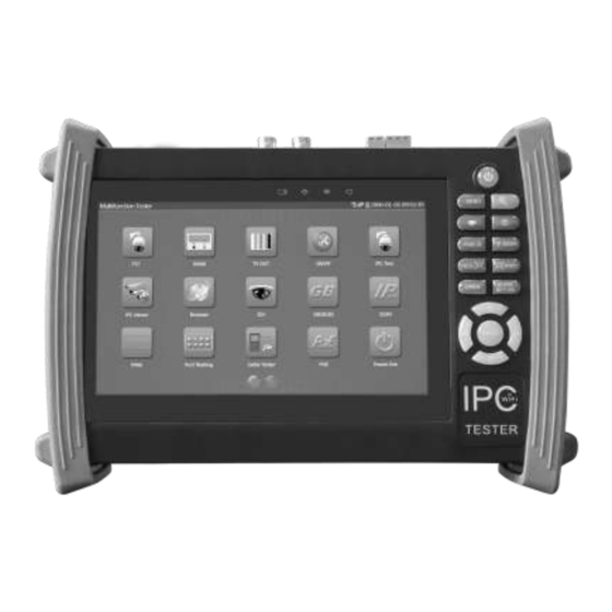
2. DIAMOND Tester Introduction 2.1 General The 7 inch touch screen DIAMOND tester is designed for maintenance and installation of IP cameras and analogue cameras as well as other security equipment. The 1280x800 resolution enables it to display network HD cameras and analogue cameras in high resolution. The unit supports many ONVIF PTZ and analogue PTZ control. - Page 13 and call camera OSD menu AHD camera image display, zoom, video record and playback, Coaxial PTZ control and call camera OSD menu HDMI signal output, supports up to 1080P. Analogueue camera image display, auto adapt and display the video format of NTSC/PAL ...
-
Page 14: Function
2.3 Function 2.3.1 Touch screen and OSD menu The DIAMOND tester combines touch screen control and physical buttons. This combination makes the tester very user friendly. The test meter allows you to move the function icons from the tester’s main menu to the APPS folder or move them back to customize the main menu 2.3.2 IP discovery... -
Page 15: Analogue Camera Test
With the ONVIF tool, you can display the image from an IP camera and use the PTZ functions. Currently the IP camera tester supports more than 70 brands’ IP cameras, such as Vista, ACTi, Dahua, Hikvision, Samsung, Honeywell and many more. -
Page 16: Ptz Controller
COLOUR BURST level: Testing the colour burst level will determine if the burst signal is sufficient to trigger the displays colour producing circuit. Burst will diminish in amplitude over longer cable runs and can get fall below the threshold for the video display to show a colour image. -
Page 17: Cable Tester
2.3.12 Cable tester Test LAN cable or telephone cable. Connect LAN cable or telephone cable with the CCTV tester and cable tester. And then the connecting status, cable type and the sequence of wires will be displayed, as well as display the serial number of the cable tester kit. -
Page 18: Ip Address Scan
2.3.19 IP address scan The IP address scan can quickly search for connected IP cameras or another network device IP address. 2.3.20 PING Test PING is the most conventional network debugging tool; it is used for testing if the connected IP camera or other network equipment is working normally and the IP address is correct. -
Page 19: Cvi Camera Test
2.3.29 CVI camera test HD CVI video surveillance testing, support720p 25,30,50,60fps / 1080p 25,30fps, when CVI signal input, HD CVI camera image display, zoom, view photos, video record and playback, Coaxial PTZ control and call up the camera OSD menu. 2.3.30 TVI camera test HD TVI video surveillance testing, support720p 25,30,50,60fps/ 1080p 25,30fps , when TVI signal input , HD TVI camera image display, zoom ,view photos ,video record and... -
Page 20: Ftp Server
2.3.37 FTP Server Start the tester’s Wi-Fi or connect the tester’s LAN port to the network. Once the tester is online, start its FTP Server and directly access files from the tester’s SD card. This also allows for the user to upgrade the tester firmware. 2.4 Packing list 1). -
Page 21: Function Interface
2.5 Function interface Page.12. - Page 22 Press more than 2 seconds, turn on or off the device ,short press to turn on or off the menu display Menu key 4xzoom the image displays. Video record Snapshot Far focus: Focus the image faraway Near focus: Focus the image nearby TELE: zoom in the image WIDE: zoom out the image Open/set ,Confirm the setting of parameters, open or enlarge the aperture...
- Page 23 Top interface Bottom interface Multimeter interface (Optional) The charge indicator: it lights red while the battery is being charged. As the charging is complete, the indicator turns off automatically The RS485/RS232 data transmission indicator: it lights red while the data is being transmitted The data received indicator: it lights red while the data is being received The power indicator: it lights green while the tester is powered on by the adapter...
-
Page 24: Operation
Video signal output(BNC interface)/ cable tracer interface Optical power meter interface (Optional) LED lamp RS485 Interface: RS485communication for the PTZ RS232 Interface: RS232 communication for the PTZ TDR cable test interface (Optional) HDMI output interface Micro SD card moveable,(comes with 4GB, supports up to 32GB) UTP cable port: UTP cable tester port/ Cable tracer port Audio output and earphone interface Audio input... -
Page 25: Instrument Connection
When the battery icon is full or the charge indicator turns off automatically, indicate the battery charging is completed Notice: When the Charge Indicator turns off, the battery is approximately 90% charged. The charging time can be extended for about 1 hour and the charging time within 12 hours will not damage the battery. - Page 26 Note:1) If the IP camera requires PoE power, then connect the IP camera to the IP tester’sLAN port . The tester will supply PoE Power for the IP camera. Click on the icon labeled POE to turn the PoE Power off or on. 2) Use the tester’s menu to turn off the tester’s PoE power supply, the PoE switch and the power sourcing equipment are allowed to connect to the tester’s PSE port, and the PoE power will be supplied to the IP camera by the tester’s LAN port.
-
Page 27: Analogue Camera Connection
3.2.2 Analogue camera connection (1) ) Connect the camera's video output to the IP tester’s VIDEO IN. The image will display on the tester after pushing the PTZ icon (2) CCTV IP Tester “VIDEO OUT” interface connect to the Video input of monitor and optical video transmitter and receiver, the image display on the tester and monitor (3) Connect the camera or the speed dome RS485 controller cable to the tester RS485 interface ,(Note positive and negative connection of the cable). - Page 28 (1) Connect the TVI camera's video output to the IP tester’s “SDI IN” interface, the image will display on the tester. The tester only come with TVI input interface. There is no TVI output interface. (2) Connect the TVI camera or the speed dome RS485 controller cable to the tester RS485 interface, (Note positive and negative connection of the cable).Support RS232 PTZ controller;...
- Page 29 Click SD card, install or remove SD card. Press function icon seconds, tip: whether moves this icon to APPS file, if some function not be often used, can move these function icons to APPS. To move an app icon to the “APPS” folder, press and hold until the “move to apps directory” appears on the screen then press OK to move it or Cancel Page.20.
-
Page 30: Ip Discovery ( Single Camera Connection)
In APPS file, Select icon and press it for seconds, tip: whether move the file to the desktop? 3.3.1 IP discovery ( Single camera connection) Press IP discovery ,the monitor will auto-scan the whole network segment, as well as auto-modify the tester‘s IP to the same network segment with the scanned camera's IP. - Page 31 Local IP: Tester’s IP address, Tester can auto-modify the tester‘s IP to the same network segment with the scanned camera's IP Discovery IP:Connected tester equipment’s IP address. If the camera is connected to the tester directly, tester will display the camera’s IP address, if tester connects to Local Area Network, it displays the current IP address.
-
Page 32: Video Monitor Test
3.3.2 Video monitor test Analogue camera test and PTZ control, click icon to enter Display the input video image, click the top menu bar icon to enter video level meter, (PEAK level, SYNC level, COLOUR BURST measurement) Select relative function on the right side Toolbar to operate , functions including “Photos”, “Snapshot”... - Page 33 A. Protocol Use the up and down arrow keys to move the yellow cursor to the “protocol ”, set corresponding Protocol and support more than thirty PTZ protocols. Such as Pelco-D,Samsung,Panasonic,Sony-EVI etc. B. Port Click and move, to “port” Select the communication port for the PTZ camera controlling (RS232/485) C.
- Page 34 PTZ Control: Press the key control the PTZ direction of rotation Press the key , to open and close the iris. Press the key , adjust the focus manually Press the key , manually adjust the zoom (2) Video and storage setting Click icon “set”,to enter and set analogue video image brightness , contrast, colour saturation, as well as the file storage way after snapshot and recording, support auto-storage and manual storage.
- Page 35 When image input, press to enter “zoom”, press it again to quit. Using the touch screen to control PTZ camera movement: Tap left, right, upward or downward on the video image to move the PTZ camera in a desired direction. Stretch two fingers outward or inward on the touch screen to zoom the image in or out.
- Page 36 (5) Video record When you click the “Record” icon, video starts recording. A red recording icon appears on the screen and begins to flash and a timer appears indicating the time elapsed for the video. Click on the “Record” icon again to stop recording and save the video file to the SD card. if select manual storage, before recording begins ,appears dialog box “Input Name”...
- Page 37 To rename or delete an image, click and hold on the file until this screen below appears Click to close and return to PTZ controller. (7) Recorded video playback Click the “Playback” icon to view your recorded videos. Tap on the video file image you want to watch.
- Page 38 To rename or delete a video, click and hold on the file until this screen appears: Video files also can play in the main menu “Video Player". (8) Video level meter Click the icon to enter, the IP camera tester has adopted hardware high-speed sampling and processing technology, can perform both NTSC and PAL video amplitude signal measurements for PEAK to PEAK, SYNC levels and COLOUR BURST chroma level.
- Page 39 While in PAL format, the unit will be mV, While in NTSC format, it will be IRE. Video signal level 140±15IRE NTSC Chroma level( COLOUR BURST) 40±5IRE SYNC signal level 40±5IRE Video signal level 1000±200mV Chroma level( COLOUR BURST) 300±35mV SYNC signal level 300±35mV Video signal PEAK to PEAK level:...
-
Page 40: Colour-Bar Generator (Tv Out)
image. For NTSC format, the Chroma standard level is 40 IRE For PAL format, the Chroma standard level is 280mV If the Chroma level is too low, the colour will not be as deep, and some details of the image will become lighter. -
Page 41: Onvif
Application A. When maintaining the dome camera, the tester sends out the colour bar by its BNC output to the monitor at the monitoring center. If the monitor receive the colour bar, it means the video transmit channel works normally. Meanwhile on the basis of the received colour bar, the monitoring center can judge if transmission has loss or interference. - Page 42 If you select ONVIF Rapid mode, the meter automatically scan different network segments for ONVIF cameras. It lists the camera name and IP address on the Device List. Tester can auto login camera and display camera image . If your IP camera does not appear after scanning the network, you can manually add an IP camera by clicking on the “Add”...
- Page 43 Click the button “Refresh”, tester will scan the ONVIF camera again. Click the newly displayed ONVIF camera on the “Device List“. The tester will show the IP camera’s relative information and settings. Live Video: Click “Live Video” to view the live video feed from the IP camera. To make the image full screen, double tap on the video.
- Page 44 ONVIF PTZ control: Tap the image in the direction you want the PTZ camera to move. Tap the left side of the image to move left, right to go right, up to go up and down to go down. Compatible IP PTZ cameras will rotate accordingly. PTZ rotation direction is displayed on top left corner of the image.
- Page 45 When the image is enlarged, if not operate on touch screen, it can operate by the keyboard ,press the key to zoon in , press the key to zoom out ,press upward and downward key to move image . If it is network video input to the tester, as the tester supports resolution up to 1080p, the input image will be very clear after it is enlarged.
- Page 46 Profiles: Click “profiles”, can view video streaming current configuration files, as well as switch between Major stream and minor stream . Preview pictures: Quickly preview and zoom in or out pictures, automatically and manual refresh Network setting: Click “Network Set “to change the IP address settings. Note: Some cameras are not fully ONVIF compliant and cannot support changing their IP address, so there is no change after saving.
- Page 47 Snapshot: Click “snapshot” to save the current image as a JPEG file on the SD card if select manual storage, appears dialog box “Input Name” , user-defined the files name(by Chinese character, English letter, or digit ) to save in SD card, if select “Auto- storage”, the tester auto stores the files after snapshot.
- Page 48 Set: Click on the “Set” icon to change Snapshot and Video recording file name settings. You can set Auto storage, which sets filenames by time or set manual storage. Click “Sure” to save file name settings. Playback: Click the “Playback” icon to view saved videos. Double click the video you want to play.
- Page 49 Video files can play in the Video player on the main menu. Page.40.
-
Page 50: Ip Camera Test
Note: Currently, the IPC Test App only supports some brands’ specific IP cameras; these include specific models made by Vista, AXIS, Dahua, Hikvision, Samsung, and many more. If the camera is not fully integrated, please use the ONVIF or RTSP apps. - Page 51 IP camera 1. When“IP camera type”is“Manual”, Pls select type by manually. Click IP camera type, Vista, AXIS, Dahua, Hikvision, Samsung IP camera etc. If the brand has offered official original protocols, pls select camera type, input IP camera address ,user name and password ,click”...
- Page 52 IP Camera's IP: Enter the IP camera’s IP address manually or click “Search” to auto-scan for the IP camera’s IP address. It is better to directly connect the IP camera to the tester so the search results will only display the camera’s IP address. If the tester is connected to a PoE switch, it will find and display several IP address IPC User Name: Enter IP camera’s user name IPC Password: Enter IP camera’s login password...
-
Page 53: Cvi Camera Test
3.3.6 CVI camera test HD CVI camera, CVI dome camera test and PTZ control, click icon to enter When HD CVI signal input, the tester will display the image resolution on the top bar. Double-taps on the screen to make the image displayed full screen. The tester supports resolution as follows 1280x720P 25FPS / 1280x720P 30FPS / 1280x720P 50FPS / 1280x720P 60FPS 1920x1080P 25FPS / 1920x1080P 30FPS... - Page 54 “Port”: select coaxial control Enter PTZ address to perform parameters setting Operation instructions, please refer to “3.3.1 PTZ (1) Video monitor test” The PTZ address in the tester must be consistent with the dome camera or decoder, then the IPC tester can test .After setting the parameter, the tester can control the PTZ and lens.
- Page 55 To control PTZ by screen touch: Tap left, right, upward and downward on the touch screen to control the PTZ rotation direction, PTZ cameras will rotate accordingly. By two fingers move outward and inward on the touch screen to zoom in and out the PTZ. To control PTZ by key buttons ...
- Page 56 Operation instructions, please refer to “3.3.1 PTZ (1) PTZ control parameters setting” (2)Coaxial camera menu setting Click “Coaxitron” and select “camera menu”, can open the dome menu Input calling dome camera menu address code, click “ok”, then press key button“ ”or click screen icon “...
- Page 57 Press arrow keys to set (3) Snapshot, record, photo viewer and video play back, please refer to “3.3.1 PTZ (1) Video monitor test” (4) Save setting Click icon “Set” on the right toolbar to enter storage setting. Support auto-storage and manual storage. When select manual storage, user can name and store the files.
-
Page 58: Tvi Camera Test
3.3.7 TVI camera test HD TVI camera, TVI dome camera test and PTZ control, Click icon to enter When HD TVI signal input, the tester will display the image resolution on the top bar. Double-taps on the screen to make the image displayed full screen. The tester supports resolution as follows: 1280x720P 25FPS / 1280x720P30FPS / 1280x720P 50FPS / 1280x720P 60FPS 1920x1080P 25FPS / 1920x1080P 30FPS / 1920x1080P 50FPS / 1920x1080P 60FPS... -
Page 59: Ahd Camera Test
More operation instructions (such as PTZ control, coaxial camera menu setting ,snapshot, recording and playback etc), please refer to“3.3.6 CVI camera test” 3.3.8 AHD camera test AHD camera, AHD dome camera test and PTZ control, Click icon to enter When AHD signal input, the tester will display the image resolution on the top bar. Double-taps on the screen to make the image displayed full screen. -
Page 60: Ip Address Scan
Click the icon“PTZ”on the right toolbar to do the corresponding setting. “Port”: select coaxial control Enter PTZ address to perform parameters setting If to coaxial PTZ control the AHD camera, no parameters setting is needed. More operation instructions please refer to “3.3.6 CVI camera test” 3.3.9 IP address scan Connect the cable to the LAN port, click icon to enter, Set your IP address search... -
Page 61: Ping Test
ports. 3.3.10 PING Test PING is the most conventional network debugging tool; it is used for testing if the connected IP camera or other network equipment’s Ethernet port is working normally and the IP address is correct Connect a network cable to the LAN port and click the icon to open the PING tool. -
Page 62: Cable Test
Application: PING testing is the most conventional network debugging tools. It is used for testing if the connected IP camera or other network equipment’s Ethernet port is working normally and the IP address is correct. It’s normal that the first data packet will be lost when test start. 3.3.11 Cable Test Click icon to enter... - Page 63 Use the blue Combination cable identifier and network cable tester’s copper pointer to touch all the cables in the bundle . You are searching at the other end. The cable that gives off the loudest tone is the cable connected to the tester. Press the + or – buttons on your blue cable identifier to adjust the volume Note:Install two AAA batteries in your blue Cable Identifier.
-
Page 64: Port Flashing
Note: The battery of the cable tracer must according to corresponding positive pole + and negative pole -, otherwise will damage the tester. Note: While the cable tracer tester is receiving the audio signal from the tester, it may be influenced by other signals and make some noise. 3.3.13 Port Flashing Connect a network cable to the meter’s “LAN”... -
Page 65: Data Monitor
Application: The tester will send special signals to make the connected LAN port flicker at special frequency, which will enable the installers to easily and quickly find the connected Ethernet cable. This function can prevent mistakenly insertion or disconnection non-corresponding cable to artificially interrupt network connection. -
Page 66: Digital Multi-Meter
3.3.15 Digital Multi-meter Click icon to enter 1) SYMBOLS: U:DC Voltage Measuring A:DC Current Measuring Ω:Resistance Measuring :Diode Testing :AC Voltage Measuring :AC Current Measuring :Continuity Testing :Capacitance Measuring AC/DC Voltage and current measurement state display The Multimeter auto adjust the range by input signal or tested Auto- range components Data hold... - Page 67 10A socket In 10A current measurement state ,indicate use 10A socket The current measurement value over the range, if in the Auto range Over range state, to switch Auto. 2) OPERATING INSTRUCTION DC Voltage Measuring WARNING! You can’t input the voltage which more than 660V DC, it’s possible to show higher voltage, but it’s may destroy the inner circuit.
- Page 68 a. Connect the black test lead to the “COM” jack and the red test lead to the “V/Ω” jack. b. select U ~ , enter the AC voltage measurement. C.the tester default Auto range status, by click “AC auto range” d.
- Page 69 has to be selected. When the value scale to be measured is unknown beforehand, set the range selector at the highest position. The maximum current of mA socket is 660mA, over-current will destroy the fuse, and will damage the meter. ...
- Page 70 When the value scale to be measured is unknown beforehand, set the range selector at the highest position. The maximum current of mA socket is 660mA; over-current will destroy the fuse, and will damage the meter. The maximum current of 10A socket is 10A, over-current will destroy the meter, and will damage the operator.
- Page 71 WARNING! When testing the circuit continuity, be sure that the power of the circuit has been shut down and all capacitors have been discharged fully. Ω a. Connect the black test lead to the “COM” jack and the red test lead to the “V/ ”...
- Page 72 Ω a. Connect the black test lead to the“ COM ” jack and the red test lead to the “V/ ” jack. b. Select “ ” to enter, enter the capacitance measurement. c. The tester default auto range status, and manual range by press upward and downward key, Auto rang by press the key “NEAR”...
- Page 73 Manual range and Auto range When testing, click “Range select " to change the value, click “Auto range “to enter Auto measurement Data hold Click “Hold data” to enter, the data be hold, the value is green. Press it again to quit. Relative value measurement Click “Relative “to enter, the tester Auto-save the data, the displayed new measurement and relative value is red colour.
-
Page 74: Media Player
if the current over the rated range ,fuse will melt to protect the meter .Pls use the same model when change the fuse, Pls opens the battery cover to change. Note: 10A socket without fuse protection, if over the current range Wrong using the 10A socket to measure the voltage, will damage the meter. -
Page 75: Audio Player
3.3.17 Audio player Click the icon to enter . The audio player only supports MP3 format Audio files. 3.3.18 LED Flashlight It is convenient for the installation or maintenance in the evening or in the dark. Click icon to enter While in the flashlight app, click the red button to turn on the LED lamp. -
Page 76: Poe Voltage Test
off. If you don’t press the red button to shut off the lamp and press the button to exit the app, the lamp will stay on. Click the Time Setting button to set a timer that will shut off the lamp. 3.3.19 PoE Voltage test Click icon to enter PoE voltage measurement... -
Page 77: Calculator
3.3.20 Calculator Click icon to enter 3.3.21 Browser Click icon to enter Type in the camera’s IP address and press “Go” to access the IP camera’s interface. NOTE: You will not be able to view live video in the web browser. For viewing video, use the IP tester‘s live camera view Apps The IP camera and IP tester be on the same network segment for the browser to interface with the camera. -
Page 78: Ip Camera Viewer
3.3.22 IP camera viewer In addition to the ONVIF app or the IPC Test app, you can use one of the mobile apps in the IPC Viewer folder to view IP camera video Click icon “IP camera viewer” to enter, run and set the mobile apps parameter to see the corresponding IP camera’s image. -
Page 79: Poe Power / Dc12V 2A And Dc 5V 2A Usb Power Output
3.3.23 PoE power / DC12V 2A and DC 5V 2A USB power output When the tester is turned on, the 12VDC and 5VDC power output functions are automatically turned on. If the IP tester is turned off, the 5VDC USB can still be used to power an external USB device. -
Page 80: Application Tools
5 Make sure you plug in your IP camera to the LAN port prior to turning on PoE power 6. Make sure the tester is full charged or more than 80% charged, otherwise the tester will shows “low power”, “not able to supply power”. 3.3.24 Application tools Click the icon to open the Application Tools folder. - Page 81 Network test (Ethernet bandwidth test) To use the Network tester, you will need two IP testers. One is used as a Server and the other as a Client. Both devices must be on the same network segment in order to communicate. Click the icon to open the Network Tester app.
- Page 82 right corner of the screen. This app is used to send packets for network speed testing. Click the “Start” button to send the packets and start testing. Network bandwidth testing can also be tested with a computer using compatible network bandwidth testing software.
- Page 83 same network segment, but with different IP address. Input Server’s IP address 192.168.0.89 in the tester and click “Start” to test network bandwidth. Or use tester as a Server, computer as test Client(select Client, input tester’s IP address to test) When you use a tester as Server, this shows the following: Page.74.
- Page 84 DHCP server: Click on the DHCP icon to open the DHCP server app. Select the “Start” check box at the top and make any desired changes to the network settings. Click “Save” to start assigning dynamic IP addresses for IP cameras and other networked devices. Click the “Refresh” button to check your Client list.
- Page 85 pls click to view the notepad , all saving contents display. Click each record bar to show the details. Press the record bar for several seconds, prompt whether delete it Link monitor: Click the icon to open the Link Monitor app. This app is used to see if an IP address is occupied by other network devices.
- Page 86 “Settings” icon on the main menu and go to IP Settings and make the desired changes. Once the desired IP addresses are added to the Link Monitor list, click “Start”. If the IP address status shows a check mark the IP address is occupied. If the IP address status shows an X the IP address is available.
- Page 87 Local IP: This is the IP testers IP address. RTSP Add: This is where you can manually enter the IP camera’s RTSP URL or click on Search to search the network for cameras that use an RTSP stream. IPC Username: Enter the IP camera’s user name. IPC Password: Enter the IP camera’s password.
- Page 88 Click “start” to trace the goal address Page.79.
-
Page 89: Apps Folder
3.3.25 APPS Folder Click icon to enter You can move desktop icons into the Tools Folder by pressing on the icon for a few seconds until the screen below appears: You can also move an icon back to the desktop by pressing on the icon for a few seconds until it asks you if you want to move the icon back to the desktop. -
Page 90: System Setting
3.3.26 System Setting Click icon to enter Language: Select your desired language: English, Chinese, Korean, Russian, Italian , Polish or Spanish. Date/Time: Set the Date/time of the IP tester IP setting: Manually set the IP address, Subnet Mask, Default Gateway and DNS address or select “Dynamic allocation”... - Page 91 it will scan for wireless networks in your area. Select the desired wireless network SSID and enter your password to connect. Brightness: Set the desired brightness of the IP tester and adjust the sleep time settings. Volume: Set volume level SD Card: Displays SD Card Capacity.
-
Page 92: Update
Version information: This displays the version information for each application Screen display rotation::Click on “Screen Rotation” to flip the IP tester’s display 180 degrees. This function is very convenient for the user to connect the LAN cable on the bottom of the unit without having to flip the unit itself. -
Page 93: Audio Test
3.4 Audio test You can test the audio input from audio pickup devices by connecting the audio pickup device to the IP tester with the supplied audio cable. 3.5 HDMI output The built in HDMI output port can output live video from an analogue or IP camera, recorded files, media files and images to HDTV monitors. -
Page 94: Dc12V 2A Power Output
Otherwise it will damage the IP camera. c. The instrument’s PoE maximum power output is 24W. If Ultra- high-power load happens, the tester will enter protection mode . 3.7 DC12V 2A power output When the IP tester is turned on, the 12VDC power output ON by default. The smaller end of the supplied converter cable connects to the tester’s DC12V/2A OUTPUT and the other end connects to the camera’s power input. - Page 95 Application Power output function is mainly used in the camera field demonstration and testing, meanwhile, for some camera installation sites, If there is no power outlet for the adapter to power the camera, the tester can offer temporary power for it. But we do not suggest tester supply power for a long time.
-
Page 96: Specifications
IP search camera quickly, auto log in and display image from the Rapid ONVIF camera IP camera type ONVIF,ONVIF PTZ, Vista, Axis, HIKVISION,Dahua, Samsung etc. CVI video signal 1 channel CVI input(BNC interface, resolution support 720p test 25,30,50,60fps/ 1080p 25,30fps 1 channel TVI input(BNC interfce),resolution support 720p... - Page 97 record and playback player will view photos and playback video HDMI output 1 channel HDMI output, supports up to 1080p 12V/2A power Output DC12V/2A power to camera output USB 5V power 5V 2A power output only ,NO data output PoE power output 48V PoE power output, Max power 24W 1 channel audio signal input and 1 channel audio signal output to Audio test...
-
Page 98: Multi-Meter Specifications
External power DC 12V 2A supply Battery Built-in 7.4V Lithium polymer battery ,6500mAh Rechargeable After charging 7~8 hours, normal working time 16 hours Parameter Capacitive touch screen, OSD menu, select your desired language: Operation setting English, Chinese, Korean, Russian, Italian or Polish, etc Auto off 1-30 (mins) General... - Page 99 AC voltage Range Accuracy Resolution 660.0mV (Manual range) ±(1.5%+6) 0.1mV 6.600V 66.00V ±(0.8%+6) 10mV 660.0V 100mV DC current Range Accuracy Resolution 6.600mA 66.00mA ±(0.5%+3) 10uA 660.0mA 100uA 10.00A ±(1%+5) 10mA AC current Range Accuracy Resolution 6.600mA 66.00mA ±(0.5%+3) 10uA 660.0mA 100uA 10.00A ±(1%+5)...
- Page 100 6.600MΩ 1KΩ 66MΩ 10KΩ ±(1.2%+5) Continuity Range Resolution Function The measurement value less 30Ω±3Ω,the tester will 660.0Ω 0.1Ω sound Diode Range Resolution Function Schottky diode:0.15~0.25V 2.0V rectifier diode:0.6~1.0V triode PN junction:0.5~0.8V Capacitance Range Accuracy Resolution 6.600nF ±(0.5%+20) 66.00nF 10pF 660.0nF 100pF ±(3.5%+8)...
Need help?
Do you have a question about the DIAMOND and is the answer not in the manual?
Questions and answers