Table of Contents
Advertisement
Quick Links
Advertisement
Table of Contents

Subscribe to Our Youtube Channel
Related Manuals for Santec SNC-240


Summary of Contents for Santec SNC-240
- Page 1 USER MANUAL IP-Camera Model SNC-240 / SNC-360 Version 1 / 2008...
- Page 2 Errors and technical alterations are omitted. SANTEC is a registered trade mark of SANYO VIDEO Vertrieb AG Germany. Other names of firms or products are trade marks or registered trade marks of particular owner. They are not in any coherence with SVV AG.
-
Page 3: Table Of Contents
Table Of Contents SAFETY PRECAUTIONS ................5 1. PRODUCT FEATURES ................. 6 1.1 P ..............6 RODUCT NSTRUCTIONS 1.2 P ................ 7 RODUCT EATURES 1.3 T .............. 8 ECHNICAL PECIFICATIONS 2. DESCRIPTION OF THE FRONT/REAR VIEWS ........10 2.1 F ............ - Page 4 4.3 TCP/IP C ..........26 OMMUNICATION OFTWARE 4.4 TCP/IP I ..............28 NSTALLATION 4.5 TCP/IP ............ 28 CONFIGURATION SETTING 4.6 C ..............30 ONNECTION ESTING 5. Operating Instructions for Image Software and Network....33 5.1 M ........... 34 ICROSOFT NTERNET XPLORER 5.1.1 Connecting the Network camera ..................34 5.1.2 Change Image Setting ......................36...
-
Page 5: Safety Precautions
SAFETY PRECAUTIONS All the following safety and operational instructions to prevent harm or injury to the operator(s) or other persons should be read carefully before the unit is activated. WARNING To prevent fire or shock hazard, avoid exposing this unit to rain or moisture. ... -
Page 6: Product Features
1. PRODUCT FEATURES 1.1 Product Instructions This user-friendly device combines cutting-edge sophistication with practical reliability and convenience. It features the self-downloading automatic video codec and other components, and is very easy to set up. The SNC-360 has especially high resolution as well as 480 TV lines, a built-in web server and a Network interface to connect you with the Internet securely and fast. -
Page 7: Product Features
1.2 Product Features SNC-240: The installation of a Codec or execution file is not necessary. The Network camera will automatically send the Codec or any component to a PC if the latter requires it. Supports two compression modes, the Motion - JPEG and the MPEG4. You can change from one to another as you wish. -
Page 8: Technical Specifications
1.3 Technical Specifications General: ‧Built-in Web Server and network interface. You don’t need a PC to operate. Installation: ‧Fast and simple installation – connect to your network and assign an IP address within a minute. The null modem cable enclosed helps you to set up without a network. Camera: ‧Digital, 24-bit color. - Page 9 ‧TCP/IP, DHCP, HTTP, UDP, FTP, SMTP, SNTP, ICMP, DDNS, DNS, UPnP Security: ‧Password protection available, unless exposure is preferred. Connections: ‧RJ 45 twisted pair cable, 10/100 Mbit Ethernet network connection. ‧Modem connection: RS-232 modem connector for dial-up use. Supports most V90 modems.
-
Page 10: Description Of The Front/Rear Views
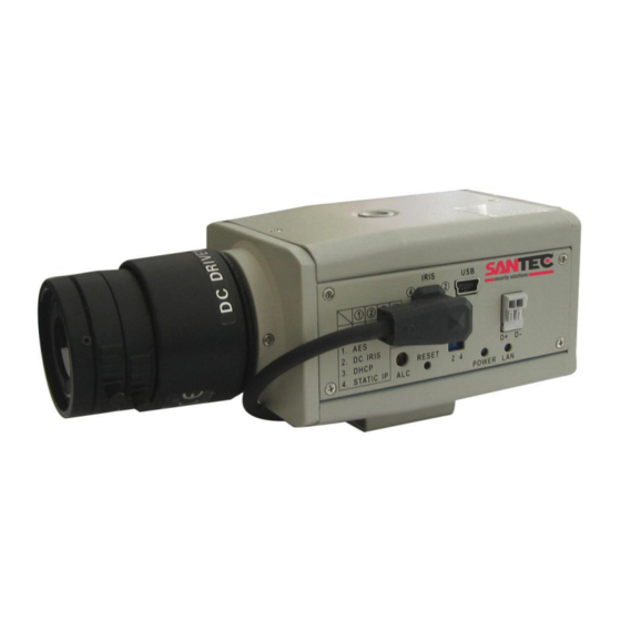
2. DESCRIPTION OF THE FRONT/REAR VIEWS 2.1 Front Panel and Rear Panel -- Front Panel -- -- Rear Panel -- ETHERNET VIDEO DC5V 1. MICROPHONE: The Network camera has an additional audio function. The device has a microphone built into its front panel which records sound. -
Page 11: Rs-232 Port & Alarm I/O
2.2 RS-232 Port & ALARM I/O 1 2 3 4 5 RS-485 D- RX: This pin is one of the RS-232 pins. It connects with the TX pin of another device. TX: This pin is one of the RS-232 pins. It connects with the RX pin of another device. Please refer to the note below on the standard RS-232 9 Pin Cable with Pin 2 and Pin 3 exchanged;... -
Page 13: Flank Panel
2.3 Flank Panel -- Right Flank Panel -- -- Left Flank Panel -- Lens Mount: This Network camera is used with either a C or a CS mount lens. ALC VR: Iris control VR. When an auto iris (DC Drive) lens is used, this VR is used to adjust the iris for different lighting environments. -
Page 14: The Usb Function
10. SD CARD Slot: This is used for system software updating and archiving / accessing critical images 2.4 The USB function By connecting the Network camera with a PC via the USB connector, the Network camera can provide two different functions. 1. - Page 15 WARNING: After changing the settings, please click the “Apply” button. All of the options will be effective after removing the USB connector.
-
Page 16: Installation
3. INSTALLATION Please follow the instructions and the diagram below to set up the system. NOTE: The Network camera is linked by its Video Out connection via a BNC connector to a monitor's Video In connection. If this connection is there, you can see some information on the monitor screen, such as the Network camera factory default Static IP address(192.168.1.168). -
Page 17: Connecting With A Dvr
3.2 CONNECTING WITH A DVR LAN CAMERA CONNECT TO VIDEO OUT BNC CONNECTOR CONNECT TO DVR VIDEO IN SD Card FROM MUX VIDEO MAIN MONITOR AUDIO RS-485 ETHERNET RS-232 10/100 ALARM MUX'S VCR IN DC12V MONITOR 3.3 CONNECTING WITH A MULTIPLEXER LAN CAMERA 1 LAN CAMERA 2 TO LAN CAMERA VIDEO OUT BNC CONNECTOR... - Page 18 2. Create a directory named LANCAM in the SD card if it does not exist. 3. Copy the file of UPDATE.BIN to the LANCAM-directory. 4. If the Network camera is running, please power it off first. 5. Insert the SD CARD into the Network camera. 6.
- Page 19 technical support. 5. In step 10, if the SD card is not removed and the Network camera does not get online as well, the updating process must be repeated again after rebooting the Network camera. 6. Make sure that the SD card is inserted in a correct position in step 5, or the Network camera will suffer permanent physical damage.
-
Page 20: Network Camera Sd Card Troubleshooting
3.5 Network camera SD card Troubleshooting 1. Check if the SD card position is correct or not. Please refer to the manual for the related information. 2. After powering the Network camera on, correctly insert the SD card, and a little icon of "SD" will show up in the upper-right corner of the monitor screen. - Page 21 4. Turn off the power before inserting the SD card. Otherwise the unit may shut down.
-
Page 22: Network Configuration
4. Network Configuration 4.1 Cable Connections Please follow the instructions below to connect your Network camera to a computer or a network and to choose a proper RJ-45 cable configuration for connections. Physical specifications of the RJ-45 cable for Ethernet Wire Type Cat. -
Page 23: Connect To A Lan Hub (Intranet)
4.1.2 Connect to a LAN Hub (INTRANET) The RJ-45 PIN configuration for connecting with a LAN Hub is shown below. TO PC NETWORK CARD LAN CAMERA RJ-45 uplink... -
Page 24: Configure Your Network Camera Network Settings
4.2 Configure Your Network camera Network Settings Upon connecting with the network hardware, you need to activate the network function and configure the proper network settings of the Network camera. 4.2.1 Enable DHCP Function This function can only work if the LAN, which the unit is connected to, has a DHCP server. If the DHCP server is working, please move the dip switch points up to 3 on the flank panel;... - Page 25 NOTE: When connecting to a network, each connected Network camera must be assigned a unique IP, which must be in the same class type as your network address. IP addresses are written as four sets of numbers separated by periods; for example, 192.168.1.1 Therefore, if the connected network is identified as Class C, for example, the first three sets of numbers of the Network camera IP address must be the same as in the network address.
-
Page 26: Tcp/Ip Communication Software
4.3 TCP/IP Communication Software Follow the procedure below to install the TCP/IP communication program in your computer. Click the Start menu from your computer, and point to the Settings/Control Panel. Double click the Network icon to enter the windows. - Page 27 Click the Configuration tag, and check if the TCP/IP is included among the network component list. If the TCP/IP is included, please process section 4.5. If it is not included, please follow section 4.4 to install the TCP/IP.
-
Page 28: Tcp/Ip Installation
4.4 TCP/IP Installation During the installation, you will be requested to insert the Windows CD-ROM. After installation, the PC may be restarted. 4.5 TCP/IP configuration setting Click Start Settings Control Panel Network. Select TCP/IP, and then click Properties. Before processing the Network camera installation in a WAN, please make sure the Internet connection works properly. - Page 29 If you are using a DHCP server, please select Obtain an IP address automatically. Any assigned IP address for the connected Network cameras must be in the same class type as the server. If there is no DHCP server, please select specify an IP address and type in the IP address of your PC.
-
Page 30: Connection Testing
4.6 Connection Testing With the previous settings, follow the instructions below to ensure whether you have established the connection successfully. Click Start → Programs → MS-DOS Prompt Type in ping 192.168.1.168, then enter. (See the sample screen below). ** This IP is the Network camera IP address that is assigned for the connected Network camera in step2. - Page 31 If you receive a response as in the sample screen below, the connection hasn’t been successfully established. Please re-check all the hardware and software installations by repeating steps 1 to 5. If you still can’t establish the connection after rechecking, please contact your dealer.
-
Page 33: Operating Instructions For Image Software And Network
5. Operating Instructions for Image Software and Network Two choices of software are available for linking with the Network camera: (1) the Microsoft Internet Explorer; and (2) the Network camera VIEWER, a network browser in a PC which provides the functions of monitoring remote zones or watching recorded data through the TCP/IP protocol. -
Page 34: Microsoft Internet Explorer
5.1 Microsoft Internet Explorer 5.1.1 Connecting the Network camera Start up the Microsoft Internet Explorer, and then follow the steps below to connect the Network camera. Click the URL block at the top of the window. Enter the URL address of the Network camera into the URL block and press the “Enter” button to enter the home page. - Page 35 Browsing images from the Network camera The images from the Network camera will be displayed on the home page while going online with the Network camera. Some buttons of the home page are provided for further setting. In the MJPEG mode or in the MPEG4 mode, there are different display formats of its home page. Homepage of MJPEG mode Homepage of MPEG4 mode ...
-
Page 36: Change Image Setting
5.1.2 Change Image Setting Please follow the steps below to change the image setting through the network if necessary. 1. Click the Image button on the home page to enter the image-setting page. SNC-240: SNC-360: Image setting page of MJPEG mode Image setting page of MPEG4 mode 2. - Page 37 Image setting page of SNC-240 Image setting page of SNC-360 5. Click the Privacy Mask button to enter the Privacy Mask page. (For SNC-360 only) 6. Click the Home button to return to the home page while the new image setting acts on the images to effect the desired changes instantly.
- Page 38 Description of function keys: SNC-240: Device Title: Type in the camera title in the given space. Resolution: Scroll to choose the image resolution from “VGA” or “QVGA”. Quality: Scroll to choose the image quality out of a spectrum of qualities ranging from “highest”, ”high”, “medium”, and “low”...
-
Page 39: Change The Network Setting
5.1.3 Change the Network Setting Please follow the steps below to change the network settings through the network if necessary. Set the network options and IP address. Click the Network button in the home page to enter the Network page. The accessible networks here are the “FTP”... - Page 40 Description of function keys: IP Address: Enter the 4-byte IP Address in the appropriate blank space (the value in each box may be anywhere between 0 and 255). Every Network camera has to own an IP address to be identified on the network. Netmask: Fill in the 4-byte Subnet Mask in the required blank spaces (usually any number between 0 and 255).
- Page 41 Change the Network Setting — FTP (MJPEG mode only). Please follow the steps below to change the FTP setting via the network if necessary to upload recording data live. 1. Click the FTP button at top left to enter the “FTP Server Setting” page. 2.
- Page 42 Change the Network Setting — SMTP (MJPEG mode only). Please follow the steps below to change the SMTP setting through the network if necessary. Click the SMTP button at upper left above to enter the “SMTP Server Setting” page. Click “My Server Requires Authentication”...
- Page 43 Change the Network Setting — SNTP. Please follow the steps below to change the SNTP setting through the network if necessary. 1. Click the SNTP button at upper left above to enter the “SNTP Server Setting” page. 2. Enter the IP Address of the SNTP server, and choose one of the time zones as and when necessary. 3.
- Page 44 Change the Network Setting — DDNS. The “Network” page has, on its upper left, the “DDNS” icon. Please follow the steps below to change the DDNS setting through the network if necessary. Click the DDNS button at upper left above to enter the “DDNS Setting” page. Click “Enable DDNS Function”...
- Page 45 Description of function keys: Enable DDNS Function: Checkmark to activate the function. DDNS Type: Click to open the list of three DDNS modes to choose from: “DynDNS”, “hn”, and “adsldns”. Click the “Apply” button and connect this website automatically and enter it. Type in your dynamic IP Address and Email Address.
- Page 46 Change the Network Setting — PPPoE. The “Network” page has, on its upper left, the “PPPoE” icon. Please follow the steps below to change the PPPoE setting through the network if necessary. Click the PPPoE button at upper left above to enter the “PPPoE Setting” page. Click the “PPPoE mode”...
- Page 47 Change the Network Setting —UPnP. The “Network” page has, on its upper left, the “UPnP” icon. Please follow the steps below to change the UPnP setting through the network if necessary. Click the UPnP button at upper left above to enter the “Universal Plug and Play” page. Click “Enable UPnP”...
- Page 48 Change the Network Setting —Network Traffic. The “Network” page has, on its upper left, the “Traffic” icon. Please follow the steps below to change the UPnP setting through the network if necessary. Click the Traffic button at upper left above to enter the “Network Traffic” page. Type in the “Maximum Upload Bandwidth”...
-
Page 49: Change The System Setting
5.1.4 Change the System Setting Please follow the steps below to change the date and time of the system setting through the network if necessary. Set the Date and Time of the system 1. Click the System button in the home page to enter the “Date And Time” page (default). 2. - Page 50 Change the System Setting — Timestamp. (For SNC-360 only) Please follow the steps below to change/add the timestamp through the network if necessary. 1. Click the Timestamp button on the left side of the “System - Date and Time” page to enter the “System - Timestamp”...
- Page 51 Change the System Setting — Users. Please follow the steps below to change/add the users’ authority through the network if necessary. Click the Users button on the left side of the “Date and Time” page to enter the “Users” page. Add, modify or delete any user’s data if necessary.
- Page 52 Change the System Setting — Digital I/O. Please follow the steps below to change the Digital I/O through the network if necessary. Click the Digital I/O button on the left side of the “Date and Time” page to enter the “Digital I/O Setting”...
- Page 53 Change the System Setting — Audio Mechanism. Please follow the steps below to change the Audio Mechanism through the network if necessary. Click the Audio Mechanism button on the left side of the “Date and Time” page to enter the “Audio Mechanism Setting”...
- Page 54 Change the System Setting — RS232 Setting. Click the RS232 Setting button on the left side of the “Date and Time” page to enter the “RS232 Setting” page. Description of function keys: Baud rate: Eight different speeds can be used: 2400 baud per second, 4800 baud, 9600 baud, 19200 baud, 28800 baud, 38400 baud, 57600 baud and 115200 baud.
- Page 55 Change the System Setting — RS485 Setting. Click the RS485 Setting button on the left side of the “Date and Time” page to enter the “RS485 Setting” page. Description of function keys: Baud rate: Eight different speeds can be used: 2400 baud per second, 4800 baud, 9600 baud, 19200 baud, 28800 baud, 38400 baud, 57600 baud and 115200 baud.
- Page 56 Change the System Setting — Update Firmware. Please follow the steps below to change the Audio Mechanism through the network if necessary. Click the Update Firmware button on the left side of the “Date and Time” page to enter the “Update Firmware”...
- Page 57 View the Event Logs. Please follow the steps below to view events through the network if necessary. Click the Events button on the upper left above to enter the “Event Log” page. Choose one of the three buttons shown on the page to view an event when necessary. The three buttons are titled “First Page”, “Previous 20”, and “Next 20”.
-
Page 58: Change The Application Setting
5.1.5 Change the Application Setting Please follow the steps below to change the application setting through the network if necessary. Change the Application Setting — FTP Application Setting (MJPEG mode only). Please follow the steps below to change the FTP setting via the network if necessary to upload recording data live. - Page 59 Change the Application Setting — SD Card Application Setting. Please follow the steps below to change the SD CARD setting via the network if necessary to upload recording data live. Click the SD card button on the top left to enter the “SD Card Application Setting” page. SD Card setting page of MJPEG mode SD Card setting page of MPEG4 mode You have an option as to which SD - card storage format to use, the MJPEG (MJPEG mode only)
- Page 60 Change the Application Setting —SMTP Application Setting (MJPEG mode only). Please follow the steps below to change the SMTP setting via the network if necessary. Click the SMTP button on the left side to enter the “SMTP Application Setting” page. Enter the attached file number as and when necessary.
- Page 61 Change the Application Setting —Language Setting. Please follow the steps below to change the Language setting via the network if necessary. Click the Language button on the left side to enter the “Language Setting” page. You have an option as to which language to use. The default is “English” Click your selected language and click "Submit"...
- Page 62 Change the Application Setting —Record Application Enable Setting. Please follow the steps below to change the setting via the network if necessary. Click the Enable Record button on the left side of the record to enter the “Record Application Enable Setting”...
- Page 63 Change the Application Setting —Record - Schedule. Click the Application button on the home page to enter the “Schedule” page. Check/uncheck any/all of the first seven boxes set vertically in the upper half of the “Schedule” page to enable/disable the programmed recording function, and vary the setting of the targeted item while it is enabled.
- Page 64 Change the Application Setting — Alarm Application Enable Setting. Please follow the steps below to change the setting via the network if necessary. Click the Enable Alarm button on the left side of the record to enter the “Alarm Application Enable Setting”...
- Page 65 Change the Application Setting —Motion Detection. Please follow the steps below to enable changes in the motion detection function of the alarm through the network if necessary. Set the motion detection: Click the Motion Detection button on the left side of the Alarm to enter the “Motion Detection”...
-
Page 66: Change The Sd Card Setting
5.1.6 Change the SD card Setting Please follow the steps below to change the SD card setting through the network if necessary. Change the SD card Setting — FILELIST of MEMORY CARD. Please follow the steps below to change the setting via the network if necessary. Click the “SD card”... -
Page 67: Change The Pan/Tilt Setting
5.1.7 Change the Pan/Tilt setting Click the Pan/Tilt button on the home page to open the Speed Dome Controller. Click “Configure” to enter to the RS232 and RS485 setting pages (please refer to Change the System Setting — RS232 Setting & Change the System Setting — RS485 Setting). Select a Speed Dome device ID from the drop-down list on the Speed Dome Controller. -
Page 68: Pppoe & Ddns
5.1.8 PPPoE & DDNS Using the PPPoE Install the XDSL software (obtained from your ISP dealer) in your PC. Search your Network camera's IP address: you can use your Network Viewer's Scan IP program, or just connect the Network camera and the Video monitor. The monitor screen will show the IP address on its right side. -
Page 69: Sanview Software
Test: Go to the Internet. Set your PC to enter the Internet. Desktop IE browser Type in the Network camera’s IP address (the same address as in the PPPoE settings and step 3 above) You can see the Network camera’s images. DDNS settings Check your Network camera’s IP address ( Scan IP software or monitor ) ... -
Page 70: Specifications
7. SPECIFICATIONS Model Number SNC-240 Image System Image Device SONY VGA CCD CCD sensor 1/4 inch progressive CCD CCD resolution 330K pixels Network throughout 2.0Mbytes /sec Video Output 1.0 Vpp, 75 ohm, composite, negative Audio 16bit, 8 kHz sample rate... - Page 71 Model Number SNC-360 Image System Image Device 1/3” Sony Super HAD CCD (with HQ1 DSP) Picture Elements 752(H) x 582(V) Horizontal Resolution 480 TV Lines Network Throughout 2.4 Mbytes/sec Video Output 1.0 Vpp, 75 ohm, composite, negative Audio 16bit, 8 kHz sample rate Microphone Built-in °...
-
Page 72: Appendix 1. -The Arp Function
APPENDIX 1. –The ARP function Setting the IP Address The Ethernet interface on the Network camera has a default IP address (192.168.1.168) that most likely needs to be changed to make it work on your local network. You need to acquire a unique IP address (ask your network administrator). - Page 73 ARP and ping from UNIX or GNU/Linux: Start a shell Type the following as superuser (root): arp -s <IP address> <Ethernet address> [or arp -s <IP address> < MAC address>] ping <IP address> Example: arp -s 192.168.1.100 00-0C-0C-00-00-01 ping 192.168.1.100 The device responds to the ping in the examples above if the new address has been configured.
-
Page 74: Appendix 2. -Register As A Ddns Member
APPENDIX 2. –Register as a DDNS member The DDNS(dynamic domain name system) is a function which is provided by an American company. Please refer to www.dyndns.com. This chapter provides the user with the basic instructions on how to register a free DDNS service. Registering for a DDNS Enter the URL www.dyndns.com. - Page 75 Figure 2 Figure 3 Click “My Services” to enter the service page. Please click the “Add Host Service” item which is below the ”My Hosts“ item, as shown in Figure 4. Click “Add Host Service”, and its 5 service items will appear. The Add Dynamic DNS Host item helps to add a new DDNS as shown in Figure 5.
- Page 76 Figure 4 Figure 5...
- Page 77 Figure 6 All we have to set in this page is the “Hostname” item. The user can choose a Sub Hostname as s/he likes from the right-hand side of the Hostname’s drop-down list. NOTE: You don’t have to set the “IP Address” in the same format as the Network camera’s IP Address.
-
Page 78: Appendix 3. -Mpeg4 Bit Rate Lookup Table Of Ip Cameras
APPENDIX 3. –MPEG4 Bit Rate Lookup Table of IP cameras 1. When frame rate is higher than 15 frames/second (15 is not including): Highest High Medium Lowest FULL D1* 2.63 2.25 1.75 1.31 0.88 Half D1* 1.25 0.75 Half VGA* 1.31 1.13 0.88...
Need help?
Do you have a question about the SNC-240 and is the answer not in the manual?
Questions and answers