Table of Contents
Advertisement
Quick Links
Advertisement
Table of Contents

Subscribe to Our Youtube Channel
Related Manuals for Santec SNC-380DN


Summary of Contents for Santec SNC-380DN
- Page 1 USER MANUAL IP-Camera Day/Night Model SNC-380DN Version 1 / 2008...
- Page 2 Errors and technical alterations are excepted. SANTEC is a registered trade mark of SANYO VIDEO Vertrieb AG. Other names of firms or products are trade marks or registered trade marks of particular owner. They are not in any coherence with SVV AG.
-
Page 3: Table Of Contents
Table Of Contents SAFETY PRECAUTIONS ................4 1. PRODUCT FEATURES ................. 5 1.1 P ..............5 RODUCT NSTRUCTIONS 1.2 P ................ 6 RODUCT EATURES 1.3 T .............. 6 ECHNICAL PECIFICATIONS 2. DESCRIPTION OF THE FRONT/REAR VIEW ........8 2.1 F ............ - Page 4 4.6 C ..............22 ONNECTION ESTING 5. Operating Instructions for Image Software and Network....24 5.1 M ........... 25 ICROSOFT NTERNET XPLORER 5.1.1 Connecting the IP camera ....................25 5.1.2 Change Image Setting ......................27 5.1.3 Change the Network Setting ....................30 5.1.4 Change the System Setting ....................
-
Page 5: Safety Precautions
SAFETY PRECAUTIONS All the following safety and operational instructions to prevent harm or injury to the operator(s) or other persons should be read carefully before the unit is activated. WARNING To prevent fire or shock hazard, avoid exposing this unit to rain or moisture. ... -
Page 6: Product Features
1. PRODUCT FEATURES 1.1 Product Instructions This user-friendly device combines cutting-edge sophistication with practical reliability and convenience, high performance with smooth remote communication. Just plug in the network cable!! You’ll get live streaming Video & Audio anytime any place! You’ll have security you can rely on! The especially high resolution has 520 TV lines, a built-in web server and a Network interface to connect you with the Internet securely and fast. -
Page 7: Product Features
1.2 Product Features 1/3" SONY Super HAD CCD. Mechanical IR Cut Filter. MPEG4 / MJPEG video compression. High resolution: 520 TV Supports POE. Embedded web server. Supports a built-in microphone. Supports motion detection. ... - Page 8 ‧ 5 levels of compression provided. The file size of an M-JPEG compressed image depends on the image’s actual content. Images with a lot of detail will generate bigger files. The level of compression determines the image quality. High compression requires smaller files while low compression gives you finer image quality along with bigger files.
-
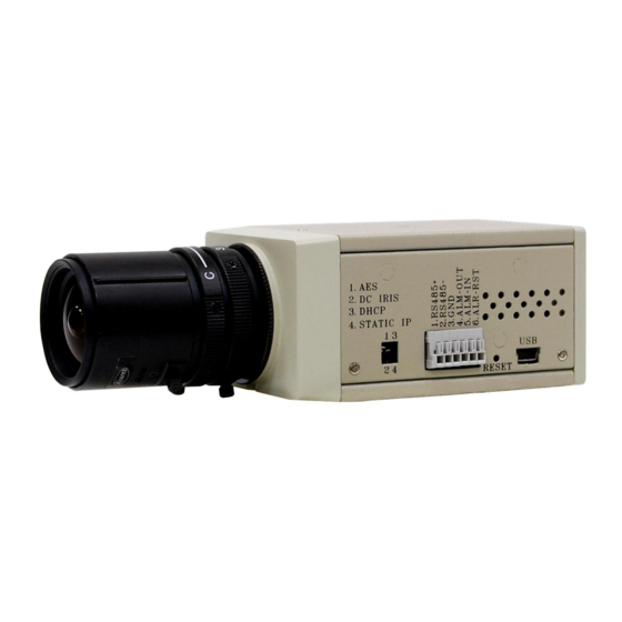
Page 9: Description Of The Front/Rear View
2. DESCRIPTION OF THE FRONT/REAR VIEW 2.1 Front Panel and Rear Panel -- Front Panel -- -- Rear Panel -- MICROPHONE: The IP camera has an additional audio function. The device has a microphone built into its front panel which records sound. Plug Inlet: A DC 12V inlet that connects to an external power supply. -
Page 10: Flank Panel
2.2 Flank Panel -- Left Flank Panel -- -- Right Flank Panel -- Lens Mount: This IP camera is used with either a C or a CS mount lens. DIP Switch: 1. AES: Auto electric shutter. 2. DC IRIS: Use an auto iris (DC drive) 3. -
Page 11: The Usb Function
2.3 The USB function By connecting the IP camera with a PC via the USB connector, the IP camera can provide two different functions. 1. Insert an SD card: As a card reader. Insert an SD card into the IP camera, then connect to the PC. You might transfer files between the SD card and the PC. -
Page 12: Installation
3. INSTALLATION Please follow the instructions and the diagram below to set up the system. NOTE: The IP camera is linked by its Video Out connection via a BNC connector to a monitor's Video In connection. If this connection is there, you can see some information on the monitor screen, such as the IP camera factory default Static IP address(192.168.1.168). -
Page 13: Connecting With A Multiplexer
3.3 CONNECTING WITH A MULTIPLEXER LAN CAMERA 1 LAN CAMERA 2 TO LAN CAMERA VIDEO OUT BNC CONNECTOR LAN CAMERA 16 3.4 UPDATING SYSTEM SOFTWARE If the system software of the IP camera needs to be upgraded, please take the following steps to safely process it. - Page 14 9. If the message "UPDATE NG RESET PLEASE" appears rather than "UPDATE OK RESET PLEASE", please write down the error messages shown on the screen and inform your technical support, while ignoring the following steps. 10. Power off the IP camera when this update process is finished, then remove the SD card from the IP camera.
-
Page 15: Ip Camera Sd Card Troubleshooting
3.5 IP camera SD card Troubleshooting 1. Check if the SD card position is correct or not. Please refer to the manual for the related information. 2. After powering the IP camera on, correctly insert the SD card, and a little icon of "SD" will show up in the upper-right corner of the monitor screen. -
Page 16: Network Configuration
4. Network Configuration 4.1 Cable Connections Please follow the instructions below to connect your IP camera to a computer or a network and to choose a proper RJ-45 cable configuration for connections. Physical specifications of the RJ-45 cable for Ethernet Wire Type Cat. -
Page 17: Connect To A Lan Hub (Intranet)
4.1.2 Connect to a LAN Hub (INTRANET) The RJ-45 PIN configuration for connecting with a LAN Hub is shown below. TO PC NETWORK CARD LAN CAMERA RJ-45 uplink... -
Page 18: Configure Your Ip Camera Network Settings
4.2 Configure Your IP camera Network Settings Upon connecting with the network hardware, you need to activate the network function and configure the proper network settings of the IP camera. 4.2.1 Enable DHCP Function This function can only work if the LAN, which the unit is connected to, has a DHCP server. If the DHCP server is working, please move the dip switch points up to 3 on the flank panel;... - Page 19 NOTE: When connecting to a network, each connected IP camera must be assigned a unique IP, which must be in the same class type as your network address. IP addresses are written as four sets of numbers separated by periods; for example, 192.168.1.1 Therefore, if the connected network is identified as Class C, for example, the first three sets of numbers of the IP camera IP address must be the same as the network address.
-
Page 20: Tcp/Ip Communication Software
4.3 TCP/IP Communication Software Follow the procedure below to install the TCP/IP communication program in your computer. Click the Start menu from your computer, and point to the Settings/Control Panel. Double click the Network icon to enter the windows. -
Page 21: Tcp/Ip Installation
Click the Configuration tag, and check if the TCP/IP is included among the network components list. If the TCP/IP is included, please process section 4.5. If it is not included, please follow section 4.4 to install the TCP/IP. 4.4 TCP/IP Installation During the installation, you will be requested to insert the Windows CD-ROM. -
Page 22: Tcp/Ip Configuration Setting
4.5 TCP/IP configuration setting Click Start Settings Control Panel Network. Select TCP/IP, and then click Properties. Before processing the IP camera installation in a WAN, please make sure the Internet connection works properly. If not, please contact your ISP provider. ... -
Page 23: Connection Testing
4.6 Connection Testing With the previous settings, follow the instructions below to ensure whether you have established the connection successfully. Click Start Programs MS-DOS Prompt Type in ping 192.168.1.168, then enter. (See the sample screen below). ** This IP is the IP camera IP address that is assigned for the connected IP camera in step2. If you receive a response as in the sample screen below, the connection hasn’t been... - Page 24 successfully established. Please re-check all the hardware and software installations by repeating steps 1 to 5. If you still can’t establish the connection after rechecking, please contact your dealer. Type Camera IP address If you receive a response as in the sample screen below, you have successfully made the connection.
-
Page 25: Operating Instructions For Image Software And Network
5. Operating Instructions for Image Software and Network Two choices of software are available for linking with the IP camera: (1) the Microsoft Internet Explorer; and (2) the SanView software, a video management software which provides the functions of controlling, monitoring and recording through the TCP/IP protocol. The details are listed as follows. -
Page 26: Microsoft Internet Explorer
5.1 Microsoft Internet Explorer 5.1.1 Connecting the IP camera Start up the Microsoft Internet Explorer, and then follow the steps below to connect the IP camera. Click the URL block at the top of the window. Enter the URL address of the IP camera into the URL block and press the “Enter” button to enter the home page. - Page 27 Browsing images from the IP camera The images from the IP camera will be displayed on the home page while going online with the IP camera. Some buttons of the home page are provided for further setting. In MJPEG mode or in MPEG4 mode, there are different display formats of its home page.
-
Page 28: Change Image Setting
5.1.2 Change Image Setting Please follow the steps below to change the image setting through the network if necessary. 1. Click the Image button on the home page to enter the image-setting page. Image setting page of MJPEG mode Image setting page of MPEG4 mode 2. - Page 29 6. Click the Day & Night button to enter the Privacy Mask page. Click the drop-down list to choose the Day & Night mode of “Auto”, “Day mode”, “Night mode” and “Schedule”. Note: In the “Schedule” mode, you can click the icon to set the Day or Night mode of each hour.
- Page 30 7. Click the Home button to return to the home page while the new image setting acts on the images to effect the desired changes instantly. (If the setting has not been changed by the above steps, any (re)entry onto the home page will find images in their earlier or original setting.) Exchange the image format Tick on one of the formats then press the Submit button.
-
Page 31: Change The Network Setting
5.1.3 Change the Network Setting Please follow the steps below to change the network setting through the network if necessary. Set the network options and IP address. Click the Network button in the home page to enter the Network page. The accessible networks here are the “FTP”, “SMTP”, “SNTP”, “DDNS”, “PPPoE”, ”UPnP”, ”IP Filter”... - Page 32 Description of function keys: IP Address: Enter the 4-byte IP Address in the appropriate blank space (the value in each box may be anywhere between 0 and 255). Every IP camera has to own an IP address to be identified on the network. Netmask: Fill in the 4-byte Subnet Mask in the required blank spaces (usually any numbers between 0 and 255).
- Page 33 Change the Network Setting — FTP (MJPEG mode only). Please follow the steps below to change the FTP setting via the network if necessary to upload recording data live. 1. Click the FTP button at top left to enter the “FTP Server Setting” page. 2.
- Page 34 Change the Network Setting — SMTP (MJPEG mode only). Please follow the steps below to change the SMTP setting through the network if necessary. Click the SMTP button at upper left above to enter the “SMTP Server Setting” page. Click “My Server Requires Authentication”...
- Page 35 Change the Network Setting — SNTP. Please follow the steps below to change the SNTP setting through the network if necessary. 1. Click the SNTP button at upper left above to enter the “SNTP Server Setting” page. 2. Enter the IP Address of the SNTP server, and choose one of the time zones as and when necessary. 3.
- Page 36 Change the Network Setting — DDNS. The “Network” page has, on its upper left, the “DDNS” icon. Please follow the steps below to change the DDNS setting through the network if necessary. Click the DDNS button at upper left above to enter the “DDNS Setting” page. Click “Enable DDNS Function”...
- Page 37 Description of function keys: Enable DDNS Function: Checkmark to activate the function. DDNS Type: Click to open the list of three DDNS modes to choose from: “DynDNS” and “hn”. Click the “Apply” button and connect this website automatically and enter it. Type in your dynamic IP Address and Email Address.
- Page 38 Change the Network Setting — PPPoE. The “Network” page has, on its upper left, the “PPPoE” icon. Please follow the steps below to change the PPPoE setting through the network if necessary. Click the PPPoE button at upper left above to enter the “PPPoE Setting” page. Please read the “PPPoE Troubleshooting”...
- Page 39 Change the Network Setting —UPnP. The “Network” page has, on its upper left, the “UPnP” icon. Please follow the steps below to change the UPnP setting through the network if necessary. Click the UPnP button at upper left above to enter the “Universal Plug and Play” page. Click “Enable UPnP”...
- Page 40 Change the Network Setting — IP Filter The “Network” page has, on its upper left, the “IP Filter” icon. Please follow the steps below to change the IP Filter setting through the network if necessary. Click the IP Filter button at upper left above to enter the “Network Setting” page. Click “Enable IP Filter”...
- Page 41 Change the Network Setting —Network Traffic. The “Network” page has, on its upper left, the “Traffic” icon. Please follow the steps below to change the UPnP setting through the network if necessary. Click the Traffic button at upper left above to enter the “Network Traffic” page. Type in the “Maximum Upload Bandwidth”...
-
Page 42: Change The System Setting
5.1.4 Change the System Setting Please follow the steps below to change the date and time of the system setting through the network if necessary. Set the Date and Time of the system 1. Click the System button in the home page to enter the “Date And Time” page (default). 2. - Page 43 Change the System Setting — Timestamp. Please follow the steps below to change/add the timestamp through the network if necessary. 1. Click the Timestamp button on the left side of the “System - Date and Time” page to enter the “System - Timestamp”...
- Page 44 Change the System Setting — Users. Please follow the steps below to change/add the users’ authority through the network if necessary. Click the Users button on the left side of the “Date and Time” page to enter the “Users” page. Add, modify or delete any user’s data if necessary.
- Page 45 Change the System Setting — Digital I/O. Please follow the steps below to change the Digital I/O through the network if necessary. Click the Digital I/O button on the left side of the “Date and Time” page to enter the “Digital I/O Setting”...
- Page 46 Change the System Setting — Audio Mechanism. Please follow the steps below to change the Audio Mechanism through the network if necessary. Click the Audio Mechanism button on the left side of the “Date and Time” page to enter the “Audio Mechanism Setting”...
- Page 47 Change the System Setting — RS485 Setting. Click the RS485 Setting button on the left side of the “Date and Time” page to enter the “RS485 Setting” page. Description of function keys: Baud rate: Eight different speeds can be used: 2400 baud per second, 4800 baud, 9600 baud, 19200 baud, 28800 baud, 38400 baud, 57600 baud and 115200 baud.
- Page 48 Change the System Setting — Update Firmware. Please follow the steps below to update the firmware through the network if necessary. Click the Update Firmware button on the left side of the “Date and Time” page to enter the “Update Firmware”...
- Page 49 Please follow the steps below to view events through the network if necessary. Click the Events button on the upper left above to enter the “Event Log” page. Choose one of the three buttons shown on the page to view an event when necessary. The three buttons are titled “First Page”, “Previous 20”, and “Next 20”.
-
Page 50: Change The Application Setting
5.1.5 Change the Application Setting Please follow the steps below to change the application setting through the network if necessary. Change the Application Setting — FTP Application Setting (MJPEG mode only). Please follow the steps below to change the FTP setting via the network if necessary to upload recording data live. - Page 51 Change the Application Setting — SD Card Application Setting. Please follow the steps below to change the SD CARD setting via the network if necessary to upload recording data live. Click the SD card button on the top left to enter the “SD Card Application Setting” page.
- Page 52 Change the Application Setting —SMTP Application Setting (MJPEG mode only). Please follow the steps below to change the SMTP setting via the network if necessary. Click the SMTP button on the left side to enter the “SMTP Application Setting” page. Enter the attached file number as and when necessary.
- Page 53 Change the Application Setting —Language Setting. Please follow the steps below to change the Language setting via the network if necessary. Click the Language button on the left side to enter the “Language Setting” page. You have an option as to which language to use. The default is “English” Click your selected language and click "Submit"...
- Page 54 Change the Application Setting —Record Application Enable Setting. Please follow the steps below to change the setting via the network if necessary. Click the Enable Record button on the left side of the record to enter the “Record Application Enable Setting”...
- Page 55 Change the Application Setting —Record - Schedule. Click the Application button on the home page to enter the “Schedule” page. Check/uncheck any/all of the first seven boxes set vertically in the upper half of the “Schedule” page to enable/disable the programmed recording function, and vary the setting of the targeted item while it is enabled.
- Page 56 Change the Application Setting — Alarm Application Enable Setting. Please follow the steps below to change the setting via the network if necessary. Click the Enable Alarm button on the left side of the record to enter the “Alarm Application Enable Setting”...
- Page 57 Change the Application Setting — Alarm - Motion Detection. Please follow the steps below to enable changes in the motion detection function of the alarm through the network if necessary. Set the motion detection: Click the Motion Detection button on the left side of the Alarm to enter the “Alarm – Motion Detection”...
-
Page 58: Change The Sd Card Setting
5.1.6 Change the SD card Setting Please follow the steps below to change the SD card setting through the network if necessary. Change the SD card Setting — FILELIST of MEMORY CARD. Please follow the steps below to change the setting via the network if necessary. Click the “SD card”... -
Page 59: Change The Pan/Tilt Setting
5.1.7 Change the Pan/Tilt setting Click the Pan/Tilt button on the home page to open the Speed Dome Controller. Click “Configure” to enter to the RS485 setting page (please refer to Change the System Setting — RS485 Setting). Select a Speed Dome device ID from the drop-down list on the Speed Dome Controller. The Controller will display the corresponding ID. -
Page 60: Pppoe & Ddns
5.1.8 PPPoE & DDNS Using the PPPoE Install the XDSL software (obtained from your ISP dealer) in your PC. Search your IP camera's IP address: you can use your Network Viewer's Scan IP program, or just connect the LAN CAM and the Video monitor. The monitor screen will show the IP address on its right side. - Page 61 Test: Go to the Internet. Set your PC to enter the Internet. Desktop IE browser Type in the IP camera IP address (the same address as in the PPPoE settings and step 3 above) You can see the LAN CAM images. DDNS settings Check your IP camera’s IP address ( Scan IP software or monitor ) ...
-
Page 62: Sanview Software
5.2 SanView software Further information about the SanView software you can find in the corresponding manual. -
Page 63: Specifications
6. SPECIFICATIONS Model Number SNC-380DN Video sensor 1/3" Sony Super HAD CCD (with HQ1 DSP) System Horizontal resolution 520 TV lines Lens C/CS mount Video Auto Iris type DC-iris Day and Night Mechanical IR Cut Filter: Auto; Color / Monochrome 2500°K ~ 9500°K... - Page 64 Video output 1.0 Vpp, 75 ohm, composite, negative, BNC x 1 Alarm I/O 1 input / 1 output Serial port RS-485 Connectors SD card Alarm and Schedule recording / update Configuration / Update Reset Factory Default LED indicator Power / Network indicator Power requirement DC12V / PoE 0°C ~ 50°C...
-
Page 65: Appendix 1. -The Arp Function
APPENDIX 1. –The ARP function Setting the IP Address The Ethernet interface on the LANCam has a default IP address (192.168.1.168) that most likely needs to be changed to make it work on your local network. You need to acquire a unique IP address (ask your network administrator). - Page 66 ARP and ping from UNIX or GNU/Linux: Start a shell Type the following as superuser (root): arp -s <IP address> <Ethernet address> [or arp -s <IP address> < MAC address>] ping <IP address> Example: arp -s 192.168.1.100 00-0C-0C-00-00-01 ping 192.168.1.100 The device responds to the ping in the examples above if the new address was configured.
-
Page 67: Appendix 2. -Register As A Ddns Member
APPENDIX 2. –Register as a DDNS member The DDNS(dynamic domain name system) is a function which is provided by an American company. Please refer to www.dyndns.com. This chapter provides the user with the basic instructions on how to register a free DDNS service. Registering for a DDNS Enter the URL www.dyndns.com. - Page 68 Figure 2 Figure 3 Click “My Services” to enter the service page. Please click the “Add Host Service” item which is below the ”My Hosts“ item, as shown in Figure 4. Click “Add Host Service”, and its 5 service items will appear. The Add Dynamic DNS Host item helps to add a new DDNS as shown in Figure 5.
- Page 69 Figure 4 Figure 5...
- Page 70 Figure 6 All we have to set in this page is the “Hostname” item. The user can choose a Sub Hostname as s/he likes from the right-hand side of the Hostname’s drop-down list. NOTE: You don’t have to set the “IP Address” in the same format as the IP camera’s IP Address.
-
Page 71: Appendix 3. -Mpeg4 Bit Rate Lookup Table Of Ip Camera
APPENDIX 3. –MPEG4 Bit Rate Lookup Table of IP camera 1. When frame rate is higher than 15 frames/second (15 is not including): Highest High Medium Lowest FULL D1 2.63 2.25 1.75 1.31 0.88 Half D1 1.25 0.75 Half VGA 1.31 1.13 0.88...
Need help?
Do you have a question about the SNC-380DN and is the answer not in the manual?
Questions and answers