Ithaca Series 90 PLUS Operator's Manual
Hide thumbs
Also See for Series 90 PLUS:
- Maintenance manual (133 pages) ,
- Programmer's manual (180 pages)
Table of Contents
Advertisement
Advertisement
Table of Contents

Subscribe to Our Youtube Channel
Related Manuals for Ithaca Series 90 PLUS


Summary of Contents for Ithaca Series 90 PLUS
- Page 1 OPERATOR'S GUIDE ® THACA ERIPHERALS...
- Page 3 WARNING: To prevent fire or shock hazard, do not expose this printer to rain or moisture.
- Page 4 Ithaca Peripherals. Trademarks PcOS® is a registered trademark of Ithaca Peripherals. IBM® is a registered trademark of the International Business Machines Corporation. Ithaca Peripherals is a Transact Technologies Incorporated Company.
-
Page 5: Federal Communications Commission Radio Frequency Interference Statement
This Ithaca Peripherals apparatus does not exceed Class A limits for radio noise emissions from digital apparatus set out in the Radio Interference Regulations of the Canadian Department of Communications. UL, CSA, VDE, CE Statement Ithaca Peripherals printers are UL & CSA Listed, VDE Certified, and carry the CE Mark. -
Page 7: Table Of Contents
TABLE OF CONTENTS ABOUT THE SERIES 90PLUS PRINTER What Is in This Book?..................1 Who Is It For? .....................1 What Does It Cover? ...................1 Where Can You Find More Information? ............2 Contacting Ithaca Peripherals..............2 Warranty Information...................3 Options .......................3 Service Information..................3 Ordering Supplies....................4 Paper......................4 Ribbon Cassettes ..................5... - Page 8 Series 90PLUS Operator’s Guide SETTING UP THE PRINTER Unpacking the Printer..................16 Check That All Items Are Present..............18 Remove the Cantilever Restraint and the Print head Carriage Restraint ..19 Remove the Paper Roll................21 Choosing a Location for the Printer ..............23 Dimensions....................23 Weight.......................23 Environmental Conditions .................23 Airflow......................23...
- Page 9 Table of Contents OPERATING THE PRINTER Operating the Keypad..................52 Indicator Lights..................52 Buttons...................... 54 AC Power Switch ..................54 Printing on Forms ....................55 Validating a Form ..................55 Slip Printing....................57 Changing the Print head..................59 Removing the Used Print head..............59 Installing the New Printhead ..............
-
Page 11: About The Series 90Plus Printer
About The Series 90PLUS Printer ABOUT THE SERIES 90PLUS PRINTER WHAT IS IN THIS BOOK? WHO IS IT FOR? This book is an operator’s guide intended for new and experienced operators. If you are going to setup, use, or maintain a Series 90PLUS Printer with any point-of-sale system, then this book is for you. -
Page 12: Where Can You Find More Information
Contact your dealer first for general information about the Series 90PLUS Printer and how it works with your system. If you need more specific information about the printer, you may contact Ithaca Peripherals directly. The Sales and Customer Service departments will be able to help you with most of your questions. -
Page 13: Warranty Information
The numbers are on a decal located on the back of the printer. You will need to repack the printer and ship it directly to Ithaca Peripherals. Be sure to keep the original packing materials and box. Please refer to “Unpacking... -
Page 14: Ordering Supplies
Series 90PLUS Operator’s Guide ORDERING SUPPLIES You may order supplies by calling Ithaca Peripherals or by faxing the order form that was shipped in the box with the printer. If you would like more forms, just call Ithaca Peripherals. ♦ Phone (607) 257-8901, and ask for the Sales department, or ♦... -
Page 15: Ribbon Cassettes
About The Series 90PLUS Printer RIBBON CASSETTES Color Supplier Stock Number Black Ithaca Peripherals 100-7565 Note: The warranty may be voided if other than genuine Ithaca Peripherals ribbons are used. TAKE-UP SPOOLS Take-Up Spool Stock Number Journal Take-up Spool 90-6415 PRINT HEAD... -
Page 16: Description Of The Series 90Plus Printer
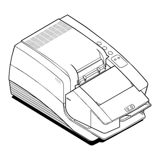
Series 90PLUS Operator’s Guide DESCRIPTION OF THE SERIES 90PLUS PRINTER The PcOS® (personal computer, point-of-sale) Series 90PLUS Printer is a stand-alone, 42-column, high-speed impact printer. The Series 90PLUS Printer performs a variety of functions in a point-of-sale environment and is available in the following models: ♦... -
Page 17: Series 90Plus Models
About The Series 90PLUS Printer SERIES 90PLUS MODELS Each of the four models in the Series 90PLUS line of printers has its own unique set of features. PcOS Model 91PLUS Receipt Printer The Model 91PLUS is a receipt printer used for applications requiring high- speed printing of receipts and single-line validation. - Page 18 Series 90PLUS Operator’s Guide PcOS Model 93PLUS Receipt, Journal, and Slip/Validation Printer The Model 93PLUS is a receipt, journal, and slip/validation printer used for applications requiring printing of up to 17 lines on inserted forms such as checks (for validation), charge slips, guest checks, or personal checks (slip mode).
-
Page 19: Standard Features
About The Series 90PLUS Printer STANDARD FEATURES The following features and items are standard on all Series 90PLUS Printers: ♦ Parallel interface – Centronics/IEEE-1284 ♦ Internal Universal Power Supply (95 to 265 VAC) ♦ Operating controls and lights • Power on/off switch and indicator •... -
Page 20: Optional Features
Series 90PLUS Operator’s Guide OPTIONAL FEATURES The optional features either replace a standard feature or enhance the operation of the printer. All optional features are installed at the factory and must be selected when the printer is ordered. ♦ RS-232C serial communication interface ♦... -
Page 21: Print Characteristics
For information about programming the printer to print a particular pitch or style, please refer to the Programmer’s Guide. You can order the Programmer’s Guide from Ithaca Peripherals. See “Contacting Ithaca Peripherals” on page 2. Pitch (characters per inch) - Page 22 Series 90PLUS Operator’s Guide...
- Page 23 About The Series 90PLUS Printer...
- Page 24 Series 90PLUS Operator’s Guide...
-
Page 25: Setting Up The Printer
Setting Up the Printer SETTING UP THE PRINTER Follow the instructions in this chapter to quickly set up the Series 90PLUS Printer. You will want to check it out first before you connect it to your system to make sure everything is working properly. You should have it ready to hook up to your system in just a few minutes. -
Page 26: Unpacking The Printer
Series 90PLUS Operator’s Guide UNPACKING THE PRINTER Print Ribbon Cassette AC Power Cord Protective Foam Pads • Warranty Card • Operator's Guide • Supplies Order Form • Journal Lock Keys (Optional) - Page 27 2. Open the box and remove the paper and supply envelope. Be sure to mail in the warranty card as soon as possible. Warranty claims cannot be processed until the printer has been registered with Ithaca Peripherals. 3. Carefully lift the printer out of the box, and set it on a sturdy, flat surface.
-
Page 28: Check That All Items Are Present
The following items are packed in the box and supply envelope. If any items are missing, contact your dealer, or if you purchased the printer directly from Ithaca Peripherals, contact the Sales department. Please refer to “Contacting Ithaca Peripherals” on page 2. -
Page 29: Remove The Cantilever Restraint And The Print Head Carriage Restraint
Setting Up the Printer REMOVE THE CANTILEVER RESTRAINT AND THE PRINT HEAD CARRIAGE RESTRAINT Note: Do not remove the packing restraints if you will be moving the printer to another location before installing it. Cantilever Restraint 1. Remove the cantilever restraint, as shown in the illustration. - Page 30 Series 90PLUS Operator’s Guide Cassette Cover 2. Open the cassette cover. Print Head Carriage Restraint 3. Remove the print head carriage restraint. The foam restraint keeps the print head from moving during shipping. Be sure to remove the restraint before operating the printer.
-
Page 31: Remove The Paper Roll
Setting Up the Printer 4. Close the cassette cover. Note: Save both restraints with the box and packing materials in case you need to send the printer for service. REMOVE THE PAPER ROLL Paper Cover 1. Open the paper cover. - Page 32 Series 90PLUS Operator’s Guide Paper Roll Rubber Band 2. Remove the paper roll and the rubber band around it. 3. Close the paper cover.
-
Page 33: Choosing A Location For The Printer
Setting Up the Printer CHOOSING A LOCATION FOR THE PRINTER The Series 90PLUS Printer is designed to be placed on point-of-sale terminals, counter tops, or any other flat, stable surface that can support the weight of the printer (about 12 pounds). Please refer to the dimensions when selecting the best possible location. -
Page 34: Installing The Ribbon Cassette
Series 90PLUS Operator’s Guide INSTALLING THE RIBBON CASSETTE Note: If you are installing the printer, the ribbon cassette is in the supply envelope. Follow these steps to install or change the ribbon cassette. Power Switch On Off Back of Printer 1. - Page 35 Setting Up the Printer Note: It is important to fit the front edge of the ribbon cassette into the carriage first. Do not place the ribbon cassette flat on the carriage. Ribbon Printhead Cassette Clamp Carriage 3. Rock the ribbon cassette forward, toward the print head and then press down on it until the tabs on the cassette snap into the clamps on the carriage.
-
Page 36: Connecting The Power Cord
Series 90PLUS Operator’s Guide CONNECTING THE POWER CORD Caution: The printer must be grounded through the three-prong power connector. Do not use a ground defeating adapter. Power Switch On Off Back of Printer 1. Be sure the power switch is turned off. Back of Printer Power... -
Page 37: Loading And Removing Paper
Setting Up the Printer LOADING AND REMOVING PAPER This section describes how to load and remove paper. Change the paper when the READY light flashes orange and green. This indicates that the paper is low. The printer will stop. You must change the paper for the printer to resume operating. - Page 38 Series 90PLUS Operator’s Guide 3. Place the roll in the printer so the paper unwinds from the bottom (front). Receipt Roller 4. Slide the edge of the paper over the receipt roller and into the paper load throat.
- Page 39 Setting Up the Printer Feed Button 5. Turn the printer on, if it is not already on, and press the FEED button until 12 inches of paper are loaded. With slight downward pressure on the receipt paper, it feeds into the throat and around the platen assembly.
- Page 40 Series 90PLUS Operator’s Guide Take-Up Spool 6. If you are loading multiple-ply paper, place the take-up spool into the printer, lining up the gears. If you are loading single-ply paper, continue with step 10. 7. Separate the paper plies. The white ply is always used for the receipt.
- Page 41 Setting Up the Printer 8. Fold the edge of the journal ply, and insert it into the slot on the take-up spool. 9. Press the FEED button to wind two or three turns of the journal ply onto the take-up spool.
- Page 42 Series 90PLUS Operator’s Guide 10. Thread the receipt paper through the slot in the paper cover, close the paper cover, and then tear off any excess receipt paper. If at any time the paper does not feed, repeat the steps. If this does not work, remove the paper and start over.
-
Page 43: Removing The Journal Take-Up Roll
Setting Up the Printer REMOVING THE JOURNAL TAKE-UP ROLL If you are changing multiple-ply paper, you must remove the journal take-up roll before putting the supply roll in. Paper Cover 1. Open the paper cover. 2. Press the FEED button to advance the journal paper past the last journal entry. - Page 44 Series 90PLUS Operator’s Guide 3. Lift the take-up spool from the printer, and cut the paper below the last journal entry. Be sure that all entries are included. 4. Slide the printed journal off the take-up core, and put it in a safe place. If the paper sticks on the core, hold the paper and twist the core in the direction opposite the way the paper is wound.
- Page 45 Setting Up the Printer Feed Button Resume Button 5. Remove the journal supply roll. Do not pull on the paper to remove unused paper from the printer. Instead, push the FEED and the RESUME buttons at the same time. This removes unused paper from the printer safely.
-
Page 46: Cutter
Series 90PLUS Operator’s Guide CUTTER The cutter is a factory installed option on the Series 90PLUS Printer. The cutter is a partial cutter and will slice the receipt paper when the receipt is finished printing. LOADING AND REMOVING PAPER WITH THE CUTTER This section describes how to load and remove paper with the optional cutter installed, if your printer does not have the optional cutter installed refer to “Loading and Removing Paper”... - Page 47 Setting Up the Printer Cutter Unit 3. Place the roll in the printer so the paper unwinds from the bottom (front). 4. Open the cutter unit. 5. Slide the edge of the paper under the cutter unit and insert the paper between the receipt roller and the paper load throat.
- Page 48 Series 90PLUS Operator’s Guide 7. If you are loading single-ply paper, continue with step 8. If you are loading multiple-ply paper, separate the paper plies. The white ply is always used for the receipt. Thread the journal ply (yellow) under the cutter unit.
- Page 49 Setting Up the Printer 11. Place the take-up spool into the printer, lining up the gears. 12. Fold the edge of the journal ply, and insert it into the slot on the take-up spool. 13. Press the FEED button to wind two or three turns of the journal ply onto the take-up spool.
-
Page 50: Removing The Journal Take-Up Roll
Series 90PLUS Operator’s Guide REMOVING THE JOURNAL TAKE-UP ROLL If you are changing multiple-ply paper, you must remove the journal take-up roll before putting the supply roll in. 1. Open the paper cover. 2. Press the FEED button to advance the journal paper past the last journal entry. - Page 51 Setting Up the Printer 5. Remove the used paper core. If there is still unused paper on the core, tear the paper out of the printer. Do not pull on the paper to remove unused paper from the printer. 6. Push the FEED and the RESUME buttons at the same time. This removes unused paper from the printer safely.
-
Page 52: Micr Reader
Series 90PLUS Operator’s Guide MICR READER The MICR (Magnetic Ink Character Recognition) reader is an option for the Series 90PLUS Printer. The reader is attached to the front of the printer and allows a document with MICR data printed on it, such as a check, to be read and positioned for printing. -
Page 53: Check Verification (Micr)
Setting Up the Printer CHECK VERIFICATION (MICR) Green MICR Characters Check 1. The host system sends a MICR read request to the printer. The Green LED lights up indicating the printer is ready to verify a check. 2. Be sure the check is face up with the MICR characters on the right. Position the check against the right side of the MICR reader table, and slide the check into the MICR reader. -
Page 54: Testing The Printer
If the character set is incomplete or does not look at all like the sample, contact your dealer or the Customer Service department at Ithaca Peripherals. Please refer to “Contacting Ithaca Peripherals” on page 2. - Page 55 The menu shown on the sample above provides different modes for running the printer. These modes are described in the PcOS Series 90PLUS Programmer’s Guide. To order this book, see “Contacting Ithaca Peripherals” on page 2. If you have accidentally entered this menu mode, turn the printer off and then...
-
Page 56: Testing The Micr Reader
Series 90PLUS Operator’s Guide TESTING THE MICR READER You can test the MICR reader to ensure that it is running properly. The next section describes how to enter the Test Mode and verify that the MICR reader is correctly reading the MICR characters. TESTING THE MICR READER 1. -
Page 57: Connecting The Cables
Cables are provided by your dealer or the system installer. If cables are unavailable, contact Ithaca Peripherals. See “Contacting Ithaca Peripherals” on page 2. Connect the Serial Cable... - Page 58 Series 90PLUS Operator’s Guide Connect the Parallel Cable Back of Printer 25-Pin Parallel Interface Connector 1. Turn the printer and the host system or PC off. 2. Connect the 25-pin parallel interface cable to the connector located on the back of the printer. Refer to the Appendix for information on the parallel cable requirements.
-
Page 59: Connecting The Cash Drawer Cables
2. Connect the cash drawer cables to the connectors located on the back of the printer. Adapters are available for connecting cash drawers equipped with BNC style connectors (the standard is a modular, telephone style connector). Contact the Customer Service department at Ithaca Peripherals for an adapter. See “Contacting Ithaca Peripherals” on page 2. -
Page 60: Setup Checklist
Series 90PLUS Operator’s Guide SETUP CHECKLIST Did you follow all of the steps to setup the printer? Here they are again for you to check off. Unpack the printer. Remove the cantilever restraint and the print head carriage restraint. Choose a location for the printer. Check the environmental conditions and the airflow around the printer. -
Page 61: Operating The Printer
Operating the Printer OPERATING THE PRINTER Once the printer has been setup, there is very little that you need to do during daily operation because most functions are controlled by the host system. This chapter describes the following few tasks that you will need to perform, some more often than others: ♦... -
Page 62: Operating The Keypad
Series 90PLUS Operator’s Guide OPERATING THE KEYPAD FEED RELEASE RESUME READY FORM Series 90 The keypad contains three buttons and two indicator lights for easy operation of the printer. The AC power switch is on the left rear side of the printer. Take a few minutes to become familiar with the keypad so that if something unexpected happens, you will be prepared. - Page 63 Operating the Printer READY Light FORM Light Condition Printer State Green Printer ready to print READY Flashing Green Paper cover open NOT READY Form Status Conditions: READY Orange Slow Flash Insert Slip Form Orange Fast Flash Insert Validation Form Green Form is Inserted Flashing Orange Slow Flash...
-
Page 64: Buttons
Series 90PLUS Operator’s Guide BUTTONS The printer includes three buttons and a power switch which have the following functions: FEED Button The FEED button advances receipt/journal paper. Note: To reverse the feed, press and hold the RESUME and FEED buttons together. -
Page 65: Printing On Forms
Operating the Printer PRINTING ON FORMS The Series 90PLUS Printer can print on inserted forms in two ways: ♦ Insert the form in the top of the printer: This operation, generally referred to as validation, allows up to 17 lines of print on a form. ♦... -
Page 66: Validation Controlled By The Printer
Series 90PLUS Operator’s Guide Validation Controlled by the Printer 1. The host system sends a validation transaction to the printer. 2. The printer opens the validation clamp, so the form can be inserted. The FORM light flashes, and the READY light is orange. Green Forms Guide Ready... -
Page 67: Slip Printing
Operating the Printer SLIP PRINTING In slip printing, the form to be printed on is inserted into the front of the printer. Slip printing is controlled by the printer. 1. The host system sends a slip transaction to the printer. 2. - Page 68 Series 90PLUS Operator’s Guide 4. The printer automatically positions the form to the top line. If the form is not positioned correctly, the printer generates an error. The READY light flashes orange, the FORM light flashes green, and the form clamp is released.
-
Page 69: Changing The Print Head
Operating the Printer CHANGING THE PRINT HEAD Replace the print head when the characters are consistently misprinting. REMOVING THE USED PRINT HEAD Caution: The print head can get very hot. Turn the printer off, and allow the print head to cool for at least three minutes before replacing it. Power Switch On Off... - Page 70 Series 90PLUS Operator’s Guide 4. Open the print head clip by grasping the tab on the right side of the clip and rotating it from right to left. Note: In the following illustration, the heatsink is not shown for clarity. 5.
-
Page 71: Installing The New Printhead
Operating the Printer INSTALLING THE NEW PRINTHEAD 1. Slide the black wire guide on the back of the print head into the slot on the carriage. Make sure the tabs on the wire guide hold the print head against the carriage. Note: the heatsink is not shown for clarity. - Page 72 Series 90PLUS Operator’s Guide 4. Close the print head clip by rotating it from left to right and latching it into place. 5. Replace the ribbon cassette, and then close the cassette cover. 6. Turn the printer back on. After the print head has been replaced, test the printer to make sure it is printing properly.
-
Page 73: Adjusting The Platen Gap
Operating the Printer ADJUSTING THE PLATEN GAP Blue Lever The gap between the print head and the platen can be adjusted to accommodate the thickness of different paper. If the gap is not set properly, the characters can smudge, the print head can jam, and the density of the characters will be less than ideal. -
Page 74: Cleaning The Printer
Series 90PLUS Operator’s Guide CLEANING THE PRINTER Cleaning the printer occasionally and keeping it well maintained will help it last longer and run better. Caution: Do not use rubbing alcohol or any kind of cleaner on any internal parts of the printer, as some parts may crack or break as a result. None of the internal parts of the printer require lubrication or routine maintenance. -
Page 75: Correcting Problems
Operating the Printer CORRECTING PROBLEMS INDICATOR LIGHTS There are two indicator lights on the right side of the printer: READY and FORM. The READY light may be red, green, or orange. The FORM light is green. READY Light FORM Light Condition Printer State Green... -
Page 76: Ready Light Flashes Red
5. Turn on the power switch. If you are unable to correct the problem, contact your dealer or the Customer Service department at Ithaca Peripherals. Please refer to “Contacting Ithaca Peripherals” on page 2. Have the error code available when you call. -
Page 77: Appendix
Appendix APPENDIX CASH DRAWER PIN ASSIGNMENTS Function Drawer 1 Drawer 2 Drawer Drive + Pin 4 Pin 4 Drawer Drive - Pin 5 Pin 1 Status Signal Pin 2 Pin 2 Status Ground Pin 3 Pin 3 Frame Ground Pin 6 Pin 6 Pin 1... -
Page 78: Serial Cable
68 Series 90PLUS Operator’s Guide SERIAL CABLE CABLE REQUIREMENTS The PcOS® Series 90PLUS Printer requires an RS-232C shielded cable, no more than 50 feet long. The cable must be UL and CSA approved. RS-232C COMMUNICATION The RS-232C interface uses the following protocol and communication characteristics: ♦... -
Page 79: Serial Cable Configurations
The following cable configurations are for different host requirements. Serial PC to Series 90PLUS Ithaca Peripherals part number: 10-2020 9-pin to 9-pin female. Use this cable for PcOS® Series 90PLUS Printers connected to personal computers or PS/2’s with 9-pin serial ports. -
Page 80: Parallel Cable
CABLE REQUIREMENTS The PcOS® Series 90PLUS Printer requires a 25-pin male D-shell connector at the printer. To connect the printer to most personal computers, use Ithaca Peripherals part number, 253-9800007, which is a 25-pin male to 25-pin male parallel interconnect cable. -
Page 81: Index
11 character set keypad sample printout, 44 buttons, 54 Checks indicator lights, 52 Verification, 42 operating, 52 cleaning, 64 contacting Ithaca Peripherals, 2 —M— Cutter Cutter, 36 MICR Reader MICR Reader, 42 —D— Testing, 46 dimensions of printer, 23 documentation... - Page 82 72 Series 90PLUS Operator’s Guide —O— reliability, 10 repacking, 17 options, 10 testing, 44 ordering documentation. See Ithaca Peripherals unpacking, 17 ordering supplies, 5 warranty, 3 weight, 23 —P— Printer Testing, 46 paper printhead loading, 27 changing, 59 ordering, 4 ordering, 5 removing, 34–35...
- Page 83 Appendix —U— paper, 4 printhead, 5 unpacking the printer, 17 ribbon cassettes, 5 take-up spools, 5 —V— —T— validation, 55 take-up spools —W— ordering, 5 test printout, 44 warranty information, 3 testing the printer, 44 weight of printer, 23 Testing the printer, 46 troubleshooting, 65...
- Page 84 74 Series 90PLUS Operator’s Guide P/N: 90-9440 Rev. C 7/99...
Need help?
Do you have a question about the Series 90 PLUS and is the answer not in the manual?
Questions and answers