Sign In
Upload
Manuals
Brands
Ithaca Manuals
Printer
PcOS series 90plus
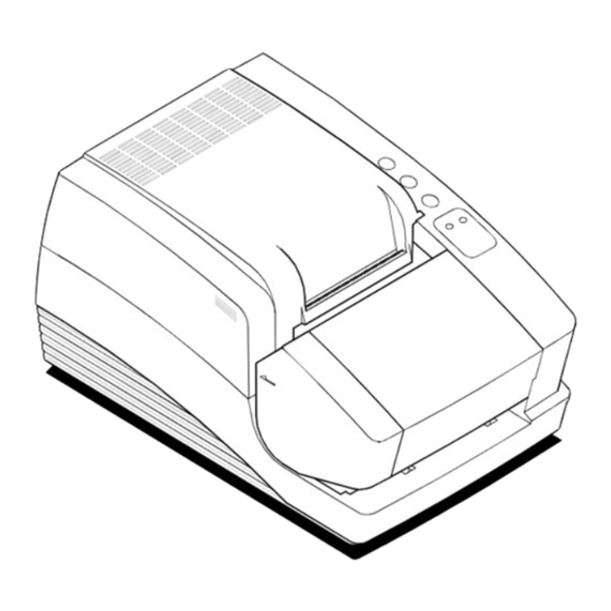
Ithaca PcOS series 90plus Flatbed Printer Manuals
Manuals and User Guides for Ithaca PcOS series 90plus Flatbed Printer. We have
3
Ithaca PcOS series 90plus Flatbed Printer manuals available for free PDF download: Programmer's Manual, Maintenance Manual, Operator's Manual
Ithaca PcOS series 90plus Programmer's Manual (180 pages)
Receipt/Validation/Journal Printers
Brand:
Ithaca
| Category:
Printer
| Size: 1 MB
Table of Contents
Change History
3
Table of Contents
7
1 Overview of the Series 90PLUS Printer
13
Warranty Information
13
Warranty Options
13
Service Information
13
What Is in this Book
13
Who Should Read this Book
13
What Does It Cover
13
Where Can You Find more Information
14
Contacting Ithaca Peripherals
14
Internet Support
14
2 General Descriptions
15
Series 90PLUS Models
15
Standard Features
15
Receipt Printer
15
Receipt/Journal Printer
16
Receipt/Journal/Validation Printer
16
Receipt/Validation Printer
16
3 General Specifications
17
Printing Specifications
17
Character Generation
17
Table 1 Character Specifications
17
Figure 1 Single-Wide Character
18
Figure 2 Character Forming
18
Physical Specifications
19
Dimensions
19
Weight
19
Electrical Characteristics
19
Self-Powered AC
19
Figure 3 Physical Dimensions
19
Interface Specifications
20
Cash Drawer
20
Parallel
20
Serial
20
Media Specifications
20
Ribbon
20
Receipt Paper
20
Table 2 Power Input Requirements
20
Receipt/Journal Paper
21
Inserted Slips and Forms
21
Slip Sensor
22
Figure 4 Slip Form Size
22
Figure 5 Slip Paper Print
22
Printable Area
23
Receipt Printing
23
Figure 6 Receipt Printable Area
23
Figure 7 Receipt Printable Area
23
Receipt Printing Without the Autocutter
23
Figure 8 Receipt Autocutter Position
24
Receipt Printing with the Autocutter
24
Validation Forms Printing
25
Figure 9 Validation Print with Normal and Narrow Print Zones
25
Table 3 Validation Lines
25
Table 4 Ten Line Validation Option
25
Validation Forms Insertion
25
Validation Forms Sensing
26
Inserted Forms Printing
26
Figure 10 Inserted Slip Using Normal and Narrow Print Zone
26
Figure 11 Normal and Narrow Print Zone Rotated Print
27
Figure 12 Multipart Forms
27
Inserted Forms Guidelines
27
MICR Reader
28
4 Control Codes Overview
29
Nomenclature
29
Standard Emulation
30
EPOS Emulation
30
IPCL Codes
30
Application Development
30
Tables and Charts
30
5 Printer Control Codes
31
Print/Paper Motion
31
Low-Level Paper Motion Control
31
Horizontal Motion Control
32
Vertical Motion Control
34
Figure 13 Data Sent to Printer for a Fine Line Feed
34
Figure 14 Example of Fine Line Feed
34
Vertical Motion
35
Character Font
38
International Character Sets and Code
40
Table 5 Language Table Identification
41
Table 6 EPOS Language Table Identification
41
Table 7 Code Page Definition Table
42
Table 8 EPOS Code Page Definition Table
42
Table 9 OCR-MA2
44
Table 10 Euro Character Substitution Matrix
45
Character Print Control
46
Table 11 Print Modes
46
Character Pitch
47
Figure 15 Examples of Print at Various Character Pitch
47
Table 12 Intercharacter Spacing Table
48
Character Attribute Commands
49
Figure 16 Data Sent to Printer for One-Line Double-Wide Print
49
Figure 17 Example of One-Line Double-Wide Print
49
Figure 18 Example of Underline, Enhanced, Emphasized, Superscript, and Subscript Print
54
Print Rotation Commands
55
Table 13 Rotated Print Spacing with 7 X 9 Font
55
Table 14 Rotated Print Spacing with 5 X 7 Font
56
Figure 19
60
Graphic Mode
61
Standard APA Graphics
61
Extended APA Graphics
63
EPOS Bit Image Graphics
64
Graphic Save
65
Programming Considerations
65
Bar Codes
68
Station Control
71
Receipt Operation
71
Receipt Paper-Error Sensor
72
Table 15 Amount of Paper Left When Paper Low Is Sensed
72
Validation and Slip Operation
74
Top Insertion Validation
74
Validation Controlled by the Host System
74
Validation Controlled by the Printer
74
Front Inserted Validation
75
Mode Selection
75
Slip Printing
75
Top Validation Operation
76
Front Slip Operation
77
Validation and Slip Operation Control
78
Table 16 Values for the Left and Right Print Margins
82
MICR Reader
84
Overview
84
Table 17 MICR Status Fields
86
Table 18 MICR Translation Characters
88
Miscellaneous Controls
89
Series 50 Compatibility Commands
93
Printer Status Set/Inquire
94
Parallel, Non-IEEE 1284 Mode Inquire
94
Serial Mode Inquire
95
Parallel, IEEE 1284 Mode Inquire
95
Dynamic Response Mode
95
Figure 20 PE to ENQ Request Timing
95
Inquire Commands
96
Extended Diagnostic Commands
104
EPOS Codes
106
Real-Time Status
106
EPOS Command Summary
106
EPOS Deviations
109
Command Descriptions
109
Control Codes Summary by Code
116
Control Codes Summary by Function
121
6 Operator Panel Controls
127
Push Buttons - Momentary Switches
127
Indicators
127
Table 19 Printer States
127
Fault Indicators
128
7 Product Self Tests
129
Level 0 Diagnostics
129
Extended Diagnostics
129
Self-Test Mode
129
Table 20 Level 0 Diagnostics
129
Hex Dump Mode
130
Configuration Mode
130
Initial Power on
130
Manual Configuration
130
Enable Remote Configuration
132
Feature Configuration
132
8 Communication Protocol and Print Buffers
146
Overview
146
Figure 21 Typical POS System
146
Figure 22 Host to Printer Link
146
Figure 23 Printer Communications Buffer Flow
147
Parallel Port
149
Parallel Port Protocol
149
Figure 24 Parallel Port Data Timing
149
Printer Buffer Size
150
One-Line Mode
150
Parallel Port Inquire IEEE 1284
150
Figure 25
150
Buffer
151
Mode 0
151
Mode 4
151
Time Outs
151
Active State
152
Inquire Responses
152
Parallel Port Inquire (Non-IEEE 1284)
152
Parallel Port Plug and Play
153
Figure 26 PE to ENQ Request Timing
153
Parallel Port Connector
155
Signal Levels
155
Table 21 Parallel Port Pin Outs
155
Serial Port
156
Serial Port Features
156
Serial Port Pin out
156
Table 22 Serial Bit Rates
156
Table 23 Serial Port Pin out
156
Signal Levels
157
Serial Port Protocol
157
Figure 27 Serial Port Flow Control Using DTR
157
Figure 28 XON/XOFF Serial Port Flow Control
158
Print Buffer Flow
159
Figure 29 Serial Buffer Operation
159
Figure 30 Print Controller Using Data
160
Printer Buffer Size
161
One-Line Mode
161
Serial Mode Plug and Play
162
Serial Device Identification
162
Using DSR
162
Serial Port Inquire
163
Figure 31 Inquire Flow
163
Remote Printer Reset
164
Reset in Serial Mode
164
Reset in Parallel Mode
164
Miscellaneous Communication Features
165
Power-Cycle Recovery
165
Data Pass-Through
165
Multidrop Configuration
165
Off-Line Active
166
Programmer's Notes
166
9 Cash Drawer Interface
167
Interface Description
167
Interface Connectors
167
Table 24 Ithaca Cash Drawer Connector
167
Table 25 Epson/Axiohm Cash Drawer Connector
167
10 Printing Graphics
168
Character Graphics
168
Figure 32 Receipt with Extended Graphic Characters
169
APA Graphics
170
Figure 33 Receipt with APA Graphics
170
Table 26 Code Page Definitions
173
Table 27 ASCII Code Chart
174
Figure 34 9-Pin Female to 9-Pin Female Serial Interconnect
175
Figure 35 9-Pin Female to 25-Pin Female Serial Interconnect
175
Advertisement
Ithaca PcOS series 90plus Maintenance Manual (133 pages)
Brand:
Ithaca
| Category:
Printer
| Size: 5 MB
Table of Contents
Canadian Department of Communications Radio Interference Statement
5
Federal Communications Commission Radio Frequency Interference Statement
5
Table of Contents
7
Troubleshooting
8
Product Information
11
What Is in this Book
11
Who Should Read this Book
11
What Does It Cover
11
Where Can You Find more Information
11
Contacting Ithaca Peripherals
11
Warranty Information
12
Options
12
Ordering Supplies
12
Paper
12
Ribbon Cassettes
13
Take-Up Spool
13
Print Head and Clamp
13
Cables
13
Description of the Series 90PLUS Printer
14
Series 90PLUS Models
14
Standard Features
16
Optional Features
16
Technical Specifications
17
Printing Specifications
17
Print Characteristics
17
Reliability
18
Dimensions
18
Weight
18
Power Requirements
18
Environmental Conditions
18
Communication Interfaces and Cash Drawer Connectors
19
Cable Requirements
19
Serial Cable
19
Parallel Cable
20
Cash Drawer Pin Assignments
21
Cleaning and Adjustments
23
Cleaning the Printer
23
Making Adjustments
23
Diagnosing the Print Quality
23
Necessary Tools
24
Adjusting the Platen Gap
25
Adjusting the Platen Parallel to the Print Head
26
Precautions for Disassembly
27
Necessary Tools
27
Disconnecting the Power Cord
28
Disconnecting the Communication Cable
29
Disconnecting the Serial Cable
29
Disconnecting the Parallel Cable
30
Disconnecting the Cash Drawer Cables
30
Removing the Ribbon Cassette
31
Installing the Ribbon Cassette
31
Print Head
33
Removing the Used Print Head
33
Installing the New Print Head
35
Removing the Covers
36
Take-Up Motor Assembly Kit
38
Mechanical Base Assembly
40
Knife Disassembly
42
25-Pin Parallel Interface Cable
44
9-Pin Serial Interface Cable
45
Cash Drawer Harnesses
46
Power Supply Assembly
47
Power Switch and AC Inlet Assembly
48
Controller Board Assembly
49
Keypad PC Board
50
Carrier/Cam Plate
51
Cam Plate
54
Carrier Assembly
57
Removing the Print Mechanism Assembly
59
Print Mechanism Assembly
60
Carriage Assembly
61
Carriage Motor
62
Line Feed Motor
63
Determining the Problem
65
LED Indicators
81
Printer Fault Indicators
82
Checking Connections and Resistance
84
Print Head
84
Space Motor Assembly
85
Line Feed Motor (Slip)
85
Line Feed Motor (Receipt)
86
Appendix A: Theory of Operation
87
Electrical Operation
88
Circuit Operation
88
Microprocessor and Peripheral Circuits
89
Microprocessor (U1: 80C154)
89
Program ROM (U4)
89
Program RAM (U2)
89
Ram (U5)
89
Lsi (M7U042-026)
89
Initialization
90
Interface Control
90
Parallel Interface
90
Serial Interface
90
Print Head Drive Circuit
91
Carriage Drive
91
Space Motor Control
91
Slit Encoder
92
Line Feed
92
Alarm Circuits
93
Drive Circuit Fault Alarm Circuit
93
Head Overheat Alarm Circuit
93
Power Supply
93
AC Input
93
Mechanical Operation
94
Print Head Mechanism and Operation
94
Space Mechanism and Operation
94
Ribbon Cartridge
95
Ribbon Feed Mechanism and Operation
95
Paper Feed Mechanism and Operation
96
Paper-Low Detection Mechanism and Operation
96
Appendix B: Parts Lists
97
Packing Materials/Publications
98
Printer Assembly
100
Paper Cover Assembly
102
Paper Cover Assembly with Lock
103
Right Cover Assembly (90-7464)
104
Right Cover Assembly with Lock (90-7470)
105
Base Cabinet and Take-Up Motor
106
Take-Up Motor Assembly (90-7462)
107
Mechanical/Electrical Base Assembly
108
Mechanical/Electrical Base Assembly (Continued)
109
Mechanism Base Assembly - Models 91PLUS and 92PLUS
110
Mechanism Base Assembly - Models 93PLUS and 94PLUS
112
Mechanism Base Assembly - Models 93PLUS and 94PLUS (Continued)
113
Knife Assembly
115
Cam Plate Assembly
117
Carrier Assembly (Standard)
118
Carrier Assembly (3" Paper Option)
119
Print Mechanism Assembly
120
Carriage Assembly
121
Carriage Motor Assembly
122
Electronic Base Assembly
123
Appendix C: Schematics
125
Ithaca PcOS series 90plus Operator's Manual (84 pages)
Brand:
Ithaca
| Category:
Printer
| Size: 2 MB
Table of Contents
Canadian Department of Communications Radio Interference Statement
5
Federal Communications Commission Radio Frequency Interference Statement
5
Table of Contents
7
About the Series 90Plus Printer
11
What Is in this Book
11
Who Is It for
11
What Does It Cover
11
Where Can You Find more Information
12
Contacting Ithaca Peripherals
12
Warranty Information
13
Options
13
Service Information
13
Ordering Supplies
14
Paper
14
Ribbon Cassettes
15
Take-Up Spools
15
Print Head
15
Cables
15
Description of the Series 90PLUS Printer
16
Series 90PLUS Models
17
Standard Features
19
Optional Features
20
Reliability
20
Print Characteristics
21
Setting up the Printer
25
Unpacking the Printer
26
Check that All Items Are Present
28
Remove the Cantilever Restraint and the Print Head Carriage Restraint
29
Remove the Paper Roll
31
Choosing a Location for the Printer
33
Dimensions
33
Weight
33
Environmental Conditions
33
Airflow
33
Installing the Ribbon Cassette
34
Connecting the Power Cord
36
Loading and Removing Paper
37
Installing the New Paper Roll
37
Removing the Journal Take-Up Roll
43
Cutter
46
Loading and Removing Paper with the Cutter
46
Installing the New Paper Roll
46
Removing the Journal Take-Up Roll
50
MICR Reader
52
Indicator Leds
52
Check Verification (MICR)
53
Testing the Printer
54
Testing the MICR Reader
56
Connecting the Cables
57
Connecting the Communication Cable
57
Connecting the Cash Drawer Cables
59
Setup Checklist
60
Operating the Printer
61
Operating the Keypad
62
Indicator Lights
62
Buttons
64
AC Power Switch
64
Printing on Forms
65
Validating a Form
65
Validation Controlled by the Printer
66
Slip Printing
67
Changing the Print Head
69
Removing the Used Print Head
69
Installing the New Printhead
71
Adjusting the Platen Gap
73
Cleaning the Printer
74
Correcting Problems
75
Indicator Lights
75
READY Light Flashes Red
76
Printer Smears Characters
76
Appendix
77
Cash Drawer Pin Assignments
77
Serial Cable
78
Cable Requirements
78
RS-232C Communication
78
Pin Assignments for 9-Pin Printer Connector
78
Serial Cable Configurations
79
Parallel Cable
80
Cable Requirements
80
Pin Assignments
80
Index
81
Advertisement
Advertisement
Related Products
Ithaca PcOS Series 80PLUS
Ithaca PcOS 150 Series
Ithaca PcOS 80 Series
Ithaca 150
Ithaca 151
Ithaca 152
Ithaca 153
Ithaca 154
Ithaca 75
Ithaca 76
Ithaca Categories
Printer
Label Maker
Adapter
Touch terminals
More Ithaca Manuals
Login
Sign In
OR
Sign in with Facebook
Sign in with Google
Upload manual
Upload from disk
Upload from URL