Ithaca PcOS series 90plus Maintenance Manual
Hide thumbs
Also See for PcOS series 90plus:
- Operator's manual (84 pages) ,
- Programmer's manual (180 pages)
Table of Contents
Advertisement
Quick Links
Advertisement
Table of Contents

Subscribe to Our Youtube Channel
Related Manuals for Ithaca PcOS series 90plus


Summary of Contents for Ithaca PcOS series 90plus
- Page 1 SERIES 90PLUS MAINTENANCE MANUAL PN: 100-9067...
- Page 3 WARNING: To prevent fire or shock hazard, do not expose this printer to rain or moisture.
- Page 4 Disclaimer Information in this publication is subject to change without notice. However, as product improvements become available, Ithaca Peripherals will make every effort to provide updated information for the products described in this publication. Ithaca Peripherals cannot guarantee that changes in software and equipment made by other manufacturers, and referred to in this publication, do not affect the applicability of the information in this publication.
-
Page 5: Federal Communications Commission Radio Frequency Interference Statement
The Series 90PLUS printer does not exceed Class A limits for radio noise emissions from digital apparatus set out in the Radio Interference Regulations of the Canadian Department of Communications. UL, CSA, VDE, CE Statement Ithaca Peripherals’ printers are UL and CSA listed, VDE certified, and carry the CE mark. -
Page 7: Table Of Contents
What is in this book? ....................1 Who should read this book? ............... 1 What does it cover? ..................1 Where can you find more information? ............1 Contacting Ithaca Peripherals..............1 Warranty Information ....................2 Options ....................... 2 Ordering Supplies ..................... 2 Paper...................... -
Page 8: Troubleshooting
Table of Content ASSEMBLY/DISASSEMBLY Precautions for Disassembly................... 17 Necessary Tools ..................17 Disconnecting the Power Cord ................18 Disconnecting the Communication Cable............... 19 Disconnecting the Serial Cable..............19 Disconnecting the Parallel Cable.............. 20 Disconnecting the Cash Drawer Cables............ 20 Removing the Ribbon Cassette ................21 Installing the Ribbon Cassette .............. - Page 9 Table of Contents Print Head....................74 Space Motor Assembly................75 Line Feed Motor (Slip)................75 Line Feed Motor (Receipt) ............... 76 APPENDIX A: THEORY OF OPERATION Electrical Operation....................78 Circuit Operation..................78 Microprocessor and Peripheral Circuits ..............79 Microprocessor (U1: 80C154) ..............79 Program ROM (U4)..................
- Page 10 Table of Content Take-up Motor Assembly (90-7462) ..............97 Mechanical/Electrical Base Assembly..............98 Mechanical/Electrical Base Assembly (continued)..........99 Mechanism Base Assembly - Models 91PLUS and 92PLUS ....... 100 Mechanism Base Assembly - Models 93PLUS and 94PLUS ....... 102 Mechanism Base Assembly - Models 93PLUS and 94PLUS (continued).... 103 Knife Assembly ....................
-
Page 11: Product Information
Contact your dealer first for general information about the Series 90PLUS printer and how it works with your system. If you need more specific information about the printer, you may contact Ithaca Peripherals directly. The Sales and Technical Support Departments will be able to help you with most of your questions. -
Page 12: Warranty Information
ORDERING SUPPLIES You may order supplies by calling Ithaca Peripherals or by faxing the order form that was shipped in the box with the printer. If you would like more forms, call Ithaca Peripherals at (607) 257-8901, and ask for the Sales Department. -
Page 13: Ribbon Cassettes
Stock Number Black Ithaca Peripherals 100-7565 Purple Ithaca Peripherals 100-7859 Note: The warranty may be voided if other than genuine Ithaca Peripherals ribbons are used. TAKE-UP SPOOL Take-up Spool Stock Number Journal take-up spool 90-6415 PRINT HEAD AND CLAMP Print Head and Clamp... -
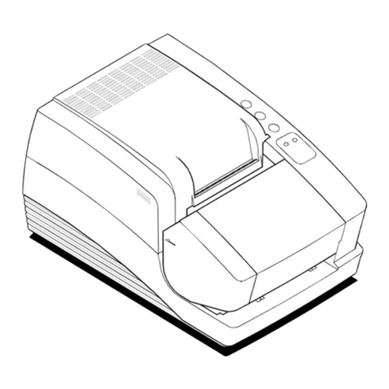
Page 14: Description Of The Series 90Plus Printer
Series 90PLUS Maintenance Manual DESCRIPTION OF THE SERIES 90PLUS PRINTER The PcOS (personal computer, point-of-sale) Series 90PLUS printer is a stand-alone, 40-column, high- speed impact printer. The Series 90PLUS printer performs a variety of functions in a point-of-sale environment and is available in the following models: ♦... - Page 15 Product Information PcOS Model 92PLUS Receipt and Journal Printer The Model 92PLUS is a receipt and journal printer used for applications requiring a transaction audit trail (journal) in addition to high-speed printing of receipts and single-line validation. ♦ 300 characters per second bidirectional printing ♦...
-
Page 16: Standard Features
Series 90PLUS Maintenance Manual STANDARD FEATURES The following features and items are standard on all Series 90PLUS printers: ♦ Centronics parallel interface with 2K buffer ♦ Internal international power supply (95 to 265 VAC) ♦ Operating controls and lights Power ON/OFF switch and indicator Paper feed button Forms release button Resume button... -
Page 17: Technical Specifications
For information about programming the printer to print a particular pitch or style, please refer to the Programmer’s Guide. You can order the Programmer’s Guide from Ithaca Peripherals. See “ Contacting Ithaca Peripherals” on page 1. -
Page 18: Reliability
Series 90PLUS Maintenance Manual RELIABILITY ♦ Mean time between failure 30,000 hours (Model 91PLUS) (except print head) ♦ Print head life 200 million characters ♦ Mean time to repair 15 minutes DIMENSIONS ♦ Width 7.30 inches (185.42 mm) ♦ Length 12.25 inches (311.15 mm) ♦... -
Page 19: Communication Interfaces And Cash Drawer Connectors
DRAWER CONNECTORS SERIAL CABLE Cable Requirements The PcOS Series 90PLUS printer requires an RS-232C shielded cable, no more than 50 feet long. The cable must be UL and CSA approved. RS-232C Communication The RS-232C interface uses the following protocol and communication characteristics: ♦... -
Page 20: Parallel Cable
Printer PARALLEL CABLE Cable Requirements The PcOS Series 90PLUS printer requires a 25-pin male D-shell connector at the printer. To connect the printer to most PC’s, use Ithaca Peripherals part number 253-9800007, 25-pin male to 25-pin male parallel interconnect cable. -
Page 21: Cash Drawer Pin Assignments
Product Information Pin Assignments Pin(s) Signal Description Direction STROBE Clock data to printer Host to printer 2 through 9 D0 - D7 Data Host to printer ACK\ Printer accepted data Printer to host BUSY Printer is busy Printer to host Paper out/status Printer to host SLCT... - Page 22 Series 90PLUS Maintenance Manual...
-
Page 23: Cleaning And Adjustments
Cleaning and Adjustments CLEANING AND ADJUSTMENTS CLEANING THE PRINTER Remove paper dust periodically by using a vacuum cleaner or air compressor. Caution: Do not use alcohol or petroleum-based chemicals to clean the printer as these will damage the plastic parts. The carriage rack is particularly sensitive and will be permanently damaged if exposed to these chemicals. -
Page 24: Necessary Tools
Series 90PLUS Maintenance Manual Print Quality Diagnosis. Examine print sample. Prints Still Replace ribbon. light? light? Check platen gap. Prints on either top or bottom, but Check parallelism. not both? Note: For additional print problems not covered in this flow chart, refer to the troubleshooting chart on page 55. -
Page 25: Adjusting The Platen Gap
Cleaning and Adjustments ADJUSTING THE PLATEN GAP Blue Lever The gap between the print head and the platen can be adjusted to accommodate the thickness of different paper. If the gap is not set properly, the characters may smudge, the print head may jam, and the density of the characters may be less than ideal. -
Page 26: Adjusting The Platen Parallel To The Print Head
Series 90PLUS Maintenance Manual ADJUSTING THE PLATEN PARALLEL TO THE PRINT HEAD Turn off the printer. Remove all paper from the printer. Remove the ribbon cassette (1). Set the range adjustment lever (2) to position 1 (towards the rear of the printer). The range adjustment lever (2) is the blue lever on the print head (4). -
Page 27: Precautions For Disassembly
Assembly and Disassembly ASSEMBLY/DISASSEMBLY PRECAUTIONS FOR DISASSEMBLY Before disassembling any part of the printer, be sure the power is turned off. Disconnect the AC power cord, the communication cable, and the cash drawer cables. Caution: The controller board and PC board keypad can easily be damaged by static electricity. Observe ESD precautions. -
Page 28: Disconnecting The Power Cord
Series 90PLUS Maintenance Manual DISCONNECTING THE POWER CORD Caution: The printer must be grounded through the three-prong power connector. Do not use a ground-defeating adapter. Power Switch On Off Back of Printer Be sure the power switch is turned off. Back of Printer Power... -
Page 29: Disconnecting The Communication Cable
Assembly and Disassembly DISCONNECTING THE COMMUNICATION CABLE Depending on the interface your system uses, either disconnect the serial or parallel communication cable from the appropriate connector on the back of the printer. DISCONNECTING THE SERIAL CABLE Back of Printer 9- pin Serial Interface Connector Turn off the printer and the host system or PC. -
Page 30: Disconnecting The Parallel Cable
Disconnect the cash drawer cables from the connectors located on the back of the printer. Adapters are available for connecting cash drawers equipped with BNC-style connectors. (A modular, telephone-style connector is standard). If you need an adapter, contact the Technical Support Department at Ithaca Peripherals. See “ Contacting Ithaca Peripherals” on page 1. -
Page 31: Removing The Ribbon Cassette
Assembly and Disassembly REMOVING THE RIBBON CASSETTE Grasp both sides of the cassette. Lift and rock the cassette towards you. Do not pull the cassette straight up. INSTALLING THE RIBBON CASSETTE Cassette Print head Tabs Carriage Groove Holding the ribbon cassette with the Mylar guide facing away from you, insert the front of the cassette into the carriage. - Page 32 Series 90PLUS Maintenance Manual Knob Cassette Tighten the ribbon by turning the knob on the cassette clockwise. Close the cassette cover. Turn the printer back on (if already installed).
-
Page 33: Print Head
Assembly and Disassembly PRINT HEAD Replace the print head when the characters are consistently misprinting. REMOVING THE USED PRINT HEAD Caution: The print head can get very hot. Power Switch On Off Back of Printer Turn off the printer, and allow the print head to cool for at least three minutes before replacing it. - Page 34 Series 90PLUS Maintenance Manual Note: In the following illustrations, the heat sink is not shown for clarity. Open the print head clip by grasping the tab on the right side of the clip and rotating it from right to left. Lift the print head straight up out of the carriage.
-
Page 35: Installing The New Print Head
Assembly and Disassembly INSTALLING THE NEW PRINT HEAD Note: In the following illustration, the heat sink is not shown for clarity. Slide the black wire guide on the back of the print head into the slot on the carriage. Make sure the tabs on the wire guide hold the print head against the carriage. -
Page 36: Removing The Covers
Series 90PLUS Maintenance Manual REMOVING THE COVERS Unlock the optional journal lock (1) located on the right cover (2). Open the paper cover (3) until it unsnaps from the base cabinet (6). Remove the take-up spindle (4). Remove the clip (5). Use needle-nose pliers to squeeze the open ends on the clip, and carefully pull it out. - Page 37 Assembly and Disassembly From the bottom of the mechanical/electrical base assembly (8), insert a flat blade screwdriver through the holes in the front, and unlatch the tabs (13) holding the cabinet bezel (9) to the base cabinet (6). Push on the left side of the cabinet bezel (9) to free the pin from the cabinet base. Remove the four screws (10) holding the base cabinet (6) to the mechanical/electrical assembly (8).
-
Page 38: Take-Up Motor Assembly Kit
Series 90PLUS Maintenance Manual TAKE-UP MOTOR ASSEMBLY KIT Models 92PLUS and 93PLUS Remove the covers. See page 26. Remove the E-ring (1) and slide off the arm (2) from the take-up motor assembly (3). - Page 39 Assembly and Disassembly Remove the screw (4) holding the take-up assembly (3) to the base cabinet (5). Release the take-up motor assembly (3) from the base cabinet (5). Move the bottom of the take-up motor assembly to the right until it clears the tab on the back wall of the base cabinet.
-
Page 40: Mechanical Base Assembly
Series 90PLUS Maintenance Manual MECHANICAL BASE ASSEMBLY... - Page 41 Assembly and Disassembly Remove the covers. See page 26. Remove the four screws (1), two in front and two in back, holding the mechanical base (2) to the electronic base assembly (3). Lift the mechanical base (2), and disconnect the following harnesses from the controller board assembly (4): cam plate motor (6);...
-
Page 42: Knife Disassembly
Series 90PLUS Maintenance Manual KNIFE DISASSEMBLY See Detail B. See Detail B. - Page 43 Assembly and Disassembly Assemble with curve facing the stud shoulder as shown. Stud shoulder Detail B Approximate location Scale 2 = 1 of ferrite bead. Detail A Bottom view Connecting rod must be assembled in this orientation. Detail C Caution: The knife blade is extremely sharp. Turn the cutter assembly upside down, remove the screw (12), and pull out the knife guide (2).
-
Page 44: 25-Pin Parallel Interface Cable
Series 90PLUS Maintenance Manual 25-PIN PARALLEL INTERFACE CABLE Remove the mechanical base assembly. See page 30. Disconnect the 25-pin parallel interface cable (1) from the connector, CN13, on the controller board (2). Unscrew the two jack screws (3) holding the cable to the electronic base (4). -
Page 45: 9-Pin Serial Interface Cable
Assembly and Disassembly 9-PIN SERIAL INTERFACE CABLE Remove the mechanical base assembly. See page 30. Disconnect the 9-pin serial interface cable (1) from the connector, CN14, on the controller board (2). Unscrew the two jack screws (3) holding the cable to the adapter plate (4). Remove the adapter plate (4) from the electronic base (5) by unscrewing the two screws (6) from the two nuts (7). -
Page 46: Cash Drawer Harnesses
Series 90PLUS Maintenance Manual CASH DRAWER HARNESSES Remove the mechanical base assembly. See page 30. Disconnect Cash Drawer Harness #1 (1) from the connector, CN11, on the controller board (2). Pull the harness up and out of the electronic base assembly (3). Disconnect Cash Drawer Harness #2 (4) from the connector, CN12, on the controller board (2). -
Page 47: Power Supply Assembly
Assembly and Disassembly POWER SUPPLY ASSEMBLY Remove the mechanical base assembly. See page 30. Disconnect the DC power harness (1) from the connector, CN10, on the controller board (2). Unscrew the three screws (3) holding the power supply (4) to the electronic base (5). Depress and push the power assembly standoff (6) through the side of the electronic base (5). -
Page 48: Power Switch And Ac Inlet Assembly
Series 90PLUS Maintenance Manual POWER SWITCH AND AC INLET ASSEMBLY White Black Black White Green with Reference Wire Orientation Yellow Stripe Remove the power supply. See page 37. Unplug the AC inlet assembly wires (7) from the power switch assembly (1). Remove the power switch assembly (1) by squeezing the tabs on the sides of the switch and pushing it out of the electronic base (2). -
Page 49: Controller Board Assembly
Assembly and Disassembly CONTROLLER BOARD ASSEMBLY Remove the mechanical base. See page 30. Disconnect the DC power harness (1), left cash drawer harness (2), right cash drawer harness (3), and the interface cable (4) from the connectors on the controller board (5). See the chart below for locations on the controller board. -
Page 50: Keypad Pc Board
Series 90PLUS Maintenance Manual KEYPAD PC BOARD Remove the mechanical base assembly. See page 30. Remove the two screws (1) holding the keypad PC board (2) to the mechanical base assembly (3). Lift the keypad PC board (2) from the mechanical base assembly (3), and disconnect the keypad harness (4). -
Page 51: Carrier/Cam Plate
Assembly and Disassembly CARRIER/CAM PLATE Models 93PLUS and 94PLUS Do not include keypad harness in Ty-wrap bundle. Remove the mechanical base assembly. See page 30. Disassemble the cam sensor flag (1) from the carrier/cam assembly (2), located under the mechanical base assembly (3). To remove, securely grab the narrow portion of the flag and pull down. - Page 52 Series 90PLUS Maintenance Manual Release the lock tabs, and slide the carrier/cam assembly (2) backwards until it is released from the mechanical base assembly (3). Carefully pull the cables (7) out of the mechanical base assembly (3). Installation note To reinsert the cam sensor flag, wiggle in the flag on the left side. Lift up on the flag and snap into place.
- Page 53 Assembly and Disassembly Models 91PLUS and 92PLUS Remove the mechanical base. See page 30. Release the lock tabs, and slide the carrier/cam assembly (1) backwards until it is released from the base (2).
-
Page 54: Cam Plate
Series 90PLUS Maintenance Manual CAM PLATE Models 93PLUS and 94PLUS Remove the carrier/cam plate. See page 41. Partially remove the pin (1) to the left until the motor shroud (2) is free from the cam plate (5). Caution: Do not pull the pin all the way out or the gear drive will not be functional. - Page 55 Assembly and Disassembly Push back on the tab behind the cam shaft (6), and lift the cam shaft out of the cam plate (5). Slide the cam shaft gear (7) off the left end of the cam shaft (6). Slide the pin (1) to the left, and remove the compound gear (8).
- Page 56 Series 90PLUS Maintenance Manual Models 91PLUS and 92PLUS Remove the carrier/cam plate. See page 41. Slide the carrier assembly (2) backward until it is released from the cam plate (1).
-
Page 57: Carrier Assembly
Assembly and Disassembly CARRIER ASSEMBLY Shown Removed for Clarity Ty Warp .50 Approx. - Page 58 Series 90PLUS Maintenance Manual Remove the cam plate. See page 44. Unsnap the receipt roller (1) from the forms comp carrier (2). Rotate the bearings (3 and 4) on each side of the platen assembly (5) forward until the platen assembly can be lifted out.
-
Page 59: Removing The Print Mechanism Assembly
Assembly and Disassembly REMOVING THE PRINT MECHANISM ASSEMBLY See Installation Note. Remove the carrier/cam plate. See page 41. Remove the carriage shaft screw (1) from the right side of the base assembly (2). Remove the screw (3) holding the print mechanism (5) to the base assembly (2). Remove the screw (4) holding the carriage rail to the base assembly (2). -
Page 60: Print Mechanism Assembly
Series 90PLUS Maintenance Manual PRINT MECHANISM ASSEMBLY Remove the print mechanism assembly. See page 49. Lift the left side of the carriage rail (15), and slide it out of the print mechanism frame (3). Slide the carriage shaft (14) to the right, and pull out of the print mechanism frame (3) and carriage assembly (16). -
Page 61: Carriage Assembly
Assembly and Disassembly CARRIAGE ASSEMBLY C u t M y l a r f r o m c a b l e a s s h o w n . Disassemble the print mechanism assembly. See page 50. Remove the print head (2). See page 23. Release the four tabs holding the ribbon feed gear assembly (3) to the carriage motor assembly (6). -
Page 62: Carriage Motor
Series 90PLUS Maintenance Manual CARRIAGE MOTOR Disassemble the carriage assembly. See page 51. To remove the print head clamp (5), gently pry the back of the clamp over the pin on the back of the carriage roller (3). Remove the front screw (4), and take off the slider (1). Remove the back two screws (4) to separate the spacer motor assembly (2) from the carriage roller (3). -
Page 63: Line Feed Motor
Assembly and Disassembly LINE FEED MOTOR Shown removed for clarity Remove the print mechanism assembly. See page 49. Remove the line feed motor (2) by prying off the Tinnerman clip (1) and removing the hex nut holding the motor to the base assembly (4). - Page 64 Series 90PLUS Maintenance Manual...
-
Page 65: Determining The Problem
Troubleshooting TROUBLESHOOTING This chapter provides solutions to problems that may occur with the printer. Use the table to determine the problem, then refer to the specified flow chart that describes the corrective action for that problem. Following the flow charts is a section that describes checking the connection circuits and resistance for the print head, space motor, and line feed motor. - Page 66 Series 90PLUS Maintenance Manual Is AC cord Reseat AC power fully seated? cord. Is primary Repair/replace wiring loose or primary wiring broken? harness. Is AC switch Replace AC switch. damaged or open? Repair/replace Is secondary secondary wiring wiring loose or harness.
- Page 67 Troubleshooting When the power is turned on, the carriage does not move. Do LED’s illuminate? Can the carriage be moved easily by hand? Remove the ribbon cassette. Is the carriage cable Can the damaged or carriage be Replace the ribbon unplugged? Replace/ cassette.
- Page 68 Series 90PLUS Maintenance Manual When power is turned on, carriage operation is abnormal; runaway, vibration, or incomplete homing occurs. Replace controller Runaway? board. Proceed to 2-2. Vibration? phase A&B being output to US pins 75, 76 on controller board? the ribbon feed assembly Reassemble.
- Page 69 Troubleshooting When the power is turned on, the homing operation is normal, but the READY LED is flashing. Flashing green? Flashing Flashing red orange? indicates printer fault. Is the paper cover closed? Refer to Table 2 Fault Indicators. Close the paper cover.
- Page 70 Series 90PLUS Maintenance Manual During data reception, neither carriage movement nor printing occurs. Verify that data is being transmitted to the printer. Can self-test be performed? Replace controller board. Is interface Reconnect interface cable connected cable. correctly? Is printer interface Run configuration configured routines.
- Page 71 Troubleshooting During data reception and printing, carriage motion is normal but nothing prints. Replace print head. Is print operation normal? Is the ribbon feed assembly Reassemble. attached correctly? Is carriage Replace carriage cable. cable broken? Is the contact pin of print head Replace the connector.
- Page 72 Series 90PLUS Maintenance Manual During data reception and printing, printing stops. Are any Refer to Table 1 LED LED’s Indicators. flashing? Is the interface Reconnect the cable connected interface cable. securely? Replace the print head. Is printer operation normal? Replace controller board.
- Page 73 Troubleshooting Wrong characters are printed, or some characters are not printed. Is interface Connect the cable cable connected properly. properly? Does self-test Replace controller print normally? board. Is printer Run configuration configured utility. correctly? Replace controller board.
- Page 74 Series 90PLUS Maintenance Manual Some dots are not printed. Is the ribbon Seat the ribbon. properly seated? Remove the print head. Are any pins broken or misaligned? Check resistance of the print head coil. Is resistance Replace the approximately print head. 20 ohms? Proceed to 6A.
- Page 75 Troubleshooting Print is not dark enough. Is the ribbbon Replace ribbon Is operation feed operating cassette. normal? properly? Replace ribbon feed gear assembly. Is ribbon wear Replace ribbon excessive? cassette. Is head gap Adjust head gap. set correctly? Are power Replace power supply supply.
- Page 76 Series 90PLUS Maintenance Manual Receipt feed is not performed. Is paper installed Install paper correctly. properly? Is receipt feed Reconnect motor to step motor controller board. plugged in? Check resistance of step motor windings. Replace receipt feed Is resistance 6.8 step motor.
- Page 77 Troubleshooting Slip feed is not performed. Is carrier Depress RELEASE assembly button. closed? Does carrier assembly close? Do step motor Correct bent pins and pins contact reinstall controller controller board. board? Proceed to Check resistance of step motor windings. Replace slip-feed step Is resistance 70 motor.
- Page 78 Series 90PLUS Maintenance Manual Carrier will not open/close properly. Does carrier move when RELEASE button is depressed? sensor flag Correctly properly install flag. Check for 12V at installed? terminals of cam plate motor when RELEASE button is depressed. Replace controller board.
- Page 79 Troubleshooting Slip will not load from the front of the printer. Does carrier assembly Proceed to 13. open and close properly? Does slip stepper motor activate when slip is inserted? Check slip-drive step motor. Is slip fed into printer? the slip-sensor flag and spring Readjust sensor flag.
- Page 80 Series 90PLUS Maintenance Manual Carrier does not operate correctly. Does carrier assembly Proceed to 13. open and close properly? Does carrier close when form is inserted? sensor flag and Readjust sensor flag. spring positioned properly? Replace controller board.
-
Page 81: Led Indicators
Troubleshooting LED INDICATORS There are two indicators. One is READY and the other is STATUS (Form). The READY indicator is tricolored: red, green, or orange. The printer can be in any of the following states. STATE READY FORM Indicator Indicator Ready Green The printer is ready to receive data and print. -
Page 82: Printer Fault Indicators
Series 90PLUS Maintenance Manual PRINTER FAULT INDICATORS If the printer indicates printer fault, the error is not recoverable. The printer must be restarted and may lose information. To aid in printer troubleshooting, the RESUME key will activate an extended diagnostic indication. - Page 83 Troubleshooting CN12 CN11 CN14 CN13 CN10 CN15 Note: This illustration is referenced by the letters in the troubleshooting flow charts and in the illustrations on the following three pages.
-
Page 84: Checking Connections And Resistance
Series 90PLUS Maintenance Manual CHECKING CONNECTIONS AND RESISTANCE PRINT HEAD The following illustration shows the connection circuit for the print head. To check the circuit of Wire #1 on the print head, use Pin 5, 6, or 7 and measure with a meter to Pin 14 at Location A. The resistance should read approximately 20 ohms. -
Page 85: Space Motor Assembly
Troubleshooting SPACE MOTOR ASSEMBLY The following illustration shows the connection circuit for the space motor assembly and the pins on the space motor. The resistance should be approximately 21 ohms between pads 17 and 16, 16 and 18, and 17 and 18 on the space motor. Pins at Connection Signals Pins on Space Motor... -
Page 86: Line Feed Motor (Receipt)
Series 90PLUS Maintenance Manual LINE FEED MOTOR (RECEIPT) The following illustration shows the connection circuit for the line feed motor. The resistance of each coil should be approximately 6.8 ohms. Pins at Connection Signals Pins on Line Feed Motor Phase 1 Phase 3 Phase 2 Phase 4... -
Page 87: Appendix A: Theory Of Operation
Appendix A: Theory of Operation APPENDIX A: THEORY OF OPERATION... -
Page 88: Electrical Operation
Series 90PLUS Maintenance Manual ELECTRICAL OPERATION CIRCUIT OPERATION The electrical section of the printer consists of the components shown in the above diagram. The control board contains the microprocessor, its peripheral circuits, and all associated drive circuits for the print head, line feed motor, slip-feed motor, journal take-up motor, cash drawers, and sensors. The printer control signals from the host system (PC or terminal) are brought directly to the control board from the rear panel on the printer. -
Page 89: Microprocessor And Peripheral Circuits
Appendix A: Theory of Operation MICROPROCESSOR AND PERIPHERAL CIRCUITS MICROPROCESSOR (U1: 80C154) The microprocessor is the nucleus of the control board. It controls the peripheral circuits. PROGRAM ROM (U4) The program ROM stores the control program for the printer. PROGRAM RAM (U2) The program RAM stores printer configuration information. -
Page 90: Initialization
Series 90PLUS Maintenance Manual INITIALIZATION The printer is initialized when the power is turned on or when the parallel interface signal, I-PRIME, is received from the host computer. Initialization begins with the RSTOUT signal output from the reset circuit to reset U1 (microprocessor), and U3 (LSI). -
Page 91: Print Head Drive Circuit
Appendix A: Theory of Operation PRINT HEAD DRIVE CIRCUIT The print head circuit drives the head magnets corresponding to the HEAD DATA 1 to 9 signals in accordance with the HEAD-ON signal allowing the print head to print characters. When the HEAD-ON signal goes high, the RC integrator (R76 and C24) determines the head drive time. The integrator lengthens the drive time if the drive voltage (+40V) lowers, and shortens the drive time if the voltage rises. -
Page 92: Slit Encoder
Series 90PLUS Maintenance Manual The SP ON/OFF signal is output during acceleration and deceleration when greater torque is required. The motor driver (MTDV) moves the space motor in accordance with these signals. Pins 9 and 11 of the MTDV are for the overvoltage (9) and overcurrent (11) protective circuits. SLIT ENCODER Space motor PHASE-A and PHASE-B signals are generated by a photo-sensor and a slit disk. -
Page 93: Alarm Circuits
Appendix A: Theory of Operation The line feed motor is held stationary with the LF HOLD signal (minute holding current: approximately 24 mA) while it is at a stop. During line feed operation, the line feed motor is driven by a large current supplied in accordance with the LF OVD signal. -
Page 94: Mechanical Operation
Series 90PLUS Maintenance Manual MECHANICAL OPERATION PRINT HEAD MECHANISM AND OPERATION The print head is spring-loaded, using a permanent magnet and can be easily removed or installed. The print head is mounted on a carriage that runs parallel to the platen and is connected with the control circuit via the circuit board. -
Page 95: Ribbon Cartridge
Appendix A: Theory of Operation The space mechanism consists of the following items: ♦ DC motor with motor gear, ♦ Carriage frame, ♦ Carriage shaft, ♦ Space rack, ♦ Slit sensor, and ♦ Slit disk. The carriage, with the print head and space motor mounted on it, moves parallel to the platen along the carriage shaft. -
Page 96: Paper Feed Mechanism And Operation
Series 90PLUS Maintenance Manual PAPER FEED MECHANISM AND OPERATION The printer has two motors that feed paper. The receipt-drive feed motor and a slip-drive feed motor, depending on what operation the printer is performing one or both of the motors will be feeding paper. Receipt Feed Motor The printer feeds paper by rotating the platen assembly, which is driven by the receipt feed motor through a speed reduction gear. -
Page 97: Appendix B: Parts Lists
Appendix B: Parts Lists APPENDIX B: PARTS LISTS... -
Page 98: Packing Materials/Publications
Series 90PLUS Maintenance Manual PACKING MATERIALS/PUBLICATIONS M A IN TEN A N C E PRO G RA M M ERS M A N U A L M A N U A L I P I THACA ERI PH ERALS NCORPORA TED THA CA ERI PHERALS N CORPORATED A Subsi d i ary of Tri dex Corporation A Su bsidiary o f T ridex Corporati on... - Page 99 Appendix B: Parts Lists ITEM NO. PART NO. DESCRIPTION 90-7578 Carton 90-7577 Foam set 90-9439 Publications kit, (includes the Operator’s Guide) 90-7570 Cantilever restraint 90-7568 Print head restraint 90-7899 Maintenance Manual 100-7586 Programmer’s Guide...
-
Page 100: Printer Assembly
Series 90PLUS Maintenance Manual PRINTER ASSEMBLY... - Page 101 Cover – Paper with lock (light tan) 90-7925 Cover – Paper with lock and knife (light tan) 98-6326 Clip – Right cover 90-6639 Label - Keypad (Ithaca) 90-7867 Label – Keypad (No logo) (light tan) 90-7892 Label – Keypad (OKI) 90-9040 Label –...
-
Page 102: Paper Cover Assembly
Series 90PLUS Maintenance Manual PAPER COVER ASSEMBLY ITEM NO. PART NO. DESCRIPTION 90-7923 Assembly – Paper Cover 90-9786* Cover – Paper without lock 90-7455 Label – Paper loading 98-6498* Magnet – Bar 90-6040* Tear-off 90-6499* Retainer – Magnet 98-9093* Screw – M3x5mm PHPS PHD * Not available as a spare part... -
Page 103: Paper Cover Assembly With Lock
Appendix B: Parts Lists PAPER COVER ASSEMBLY WITH LOCK ITEM NO. PART NO. DESCRIPTION 90-7924 Assembly – Paper cover with lock 90-9789* Cover – Paper with lock 90-7455 Label – Paper loading 98-6498* Magnet – Bar 90-6040* Tear-off 90-6499* Retainer – Magnet 98-9093* Screw –... -
Page 104: Right Cover Assembly (90-7464)
Series 90PLUS Maintenance Manual RIGHT COVER ASSEMBLY (90-7464) ITEM NO. PART NO. DESCRIPTION 90-6322 Cover – Right (Ithaca) 90-6418 Button – PCB (green) 90-6323 Cover – Right (OKI) 90-6419 Button – PC board (OKI, gray) 90-6639 Label – Keypad (Ithaca)* 90-7867 Label –... -
Page 105: Right Cover Assembly With Lock (90-7470)
Appendix B: Parts Lists RIGHT COVER ASSEMBLY WITH LOCK (90-7470) ITEM NO. PART NO. DESCRIPTION 90-6322 Cover – Right (Ithaca) 90-6418 Button – PCB (green) 90-6429 Assembly – Journal lock 90-6419 Button – PC board (OKI gray) 90-6639 Label – Keypad (Ithaca)* 90-7867 Label –... -
Page 106: Base Cabinet And Take-Up Motor
Series 90PLUS Maintenance Manual BASE CABINET AND TAKE-UP MOTOR ITEM NO. PART NO. DESCRIPTION 98-0611 Screw – M3x6mm PHPS PHD 90-7462 Assembly – Take-up motor 90-6641 Cable – Journal take-up intermediate 90-6320 Base – Cabinet (light tan) 90-6321 Bezel – Cabinet (light tan) 90-6460 520-9800002 Keeper –... -
Page 107: Take-Up Motor Assembly (90-7462)
Appendix B: Parts Lists TAKE-UP MOTOR ASSEMBLY (90-7462) Notes 1. White wire of 90-6624 to be connected to negative (-) terminal of 06-1187. 2. Black wire of 90-6624 to be connected to positive (+) terminal of 06-1187. ITEM NO. PART NO. DESCRIPTION 06-1112* Gear –... -
Page 108: Mechanical/Electrical Base Assembly
Series 90PLUS Maintenance Manual MECHANICAL/ELECTRICAL BASE ASSEMBLY RECEIPT STEPPER MOTOR RJ11 #2 CAM PLATE MOTOR HARNESS RJ11 #1... -
Page 109: Mechanical/Electrical Base Assembly (Continued)
Appendix B: Parts Lists MECHANICAL/ELECTRICAL BASE ASSEMBLY (CONTINUED) ITEM NO. PART NO. DESCRIPTION 98-0611 Screw – M3x6mm PHPS PHD 98-2033 Jack screw 90-6641 Cable – Journal take-up intermediate 90-7550* Assembly – Mechanism base M93PLUS and M94PLUS 90-9294* Assembly – Mechanism base (3” paper; M93PLUS and M94PLUS) 90-7582* Assembly –... -
Page 110: Mechanism Base Assembly - Models 91Plus And 92Plus
Series 90PLUS Maintenance Manual MECHANISM BASE ASSEMBLY - MODELS 91PLUS AND 92PLUS... - Page 111 Appendix B: Parts Lists 101 ITEM NO. PART NO. DESCRIPTION 90-6619 Cable – Keypad 90-7887* Assembly – Print mechanism 90-9043 Assembly – Carrier/Cam Plate (standard) 90-9292 Assembly – Carrier/Cam Plate (3” paper) 90-6054 Mylar – Head cable 98-0611 Screw – M3x6mm PHPS PHD 90-01160 Base assembly 06-0579...
-
Page 112: Mechanism Base Assembly - Models 93Plus And 94Plus
Series 90PLUS Maintenance Manual MECHANISM BASE ASSEMBLY - MODELS 93PLUS AND 94PLUS... -
Page 113: Mechanism Base Assembly - Models 93Plus And 94Plus (Continued)
Appendix B: Parts Lists 103 MECHANISM BASE ASSEMBLY - MODELS 93PLUS AND 94PLUS (CONTINUED) - Page 114 Series 90PLUS Maintenance Manual ITEM NO. PART NO. DESCRIPTION 90-6619 Harness – Keypad 90-6032* Flag – Cam Sensor 90-01473* Flag - Bank validation 90-9969* Flag - Slip-stop sensor 90-9970* Bracket - Magnet mounting 98-6498 Magnet 90-7433 Assembly – Print mechanism M93PLUS and M94 PLUS 90-6054 Mylar –...
-
Page 115: Knife Assembly
Appendix B: Parts Lists 105 KNIFE ASSEMBLY Detail A Bottom view... - Page 116 Series 90PLUS Maintenance Manual ITEM NO. PART NO. DESCRIPTION 90-01817 Assembly - Knife Module 90-01255* Frame - Knife 90-6071* Guide - Knife 15-01323* Plate - Knife 15-01900* Blade - Moving (Ground) 90-9673* Gear - Knife, 36 Tooth 90-9742* Pin - Knife 15-01872* Rod - Connecting 15-01326*...
-
Page 117: Cam Plate Assembly
Appendix B: Parts Lists 107 CAM PLATE ASSEMBLY ITEM NO. PART NO. DESCRIPTION 90-01171 Plate – Cam 90-6031 Pin – 0.078 inch diameter 90-6035 Gear – Compound 90-01158 Shroud – Motor 90-01463 Shaft – Cam 90-6063 Gear – Cam shaft 90-7436 Assembly –... -
Page 118: Carrier Assembly (Standard)
Series 90PLUS Maintenance Manual CARRIER ASSEMBLY (STANDARD) ITEM NO. PART NO. DESCRIPTION 90-01464 Carrier – Forms comp 90-9745 Shaft – Pressure 90-6018 Plate – Spring 90-6025 Bearing – Platen 90-6024 Roller – Receipt 90-6026 Springs – Forms comp 90-9092 Assembly – Forms-in sensor 90-9684 Assembly –... -
Page 119: Carrier Assembly (3" Paper Option)
Appendix B: Parts Lists 109 CARRIER ASSEMBLY (3” PAPER OPTION) ITEM NO. PART NO. DESCRIPTION 90-01464 Carrier – Forms comp 90-9745 Shaft – Pressure roll 90-6018 Plate – Spring 90-6025 Bearing – Platen 90-6024 Roller – Receipt 90-6026 Springs – Forms comp 90-9092 Assembly –... -
Page 120: Print Mechanism Assembly
Series 90PLUS Maintenance Manual PRINT MECHANISM ASSEMBLY ITEM NO. PART NO. DESCRIPTION 06-0546 Gear – Idler 06-0682 Bearing – Feed roll 90-6050 Frame – Print mechanism 90-6052 Shaft – Slip drive R90-6056 Rack – Space 90-6057 Pin – 0.098” diameter 90-6058 Gear –... -
Page 121: Carriage Assembly
Appendix B: Parts Lists 111 CARRIAGE ASSEMBLY ITEM NO. PART NO. DESCRIPTION R06-0574 Connector – Print head R90-7337 Print head R90-7338 Assembly – Ribbon feed gear R90-7339 Rubber – Contact pressure R90-7340 Cable – Head 90-7431* Assembly – Carriage motor * Not available as a spare part... -
Page 122: Carriage Motor Assembly
Series 90PLUS Maintenance Manual CARRIAGE MOTOR ASSEMBLY ITEM NO. PART NO. DESCRIPTION R06-0575 Slider – OKI 98-7280 Assembly – Space motor R90-7341 Roller – Carriage R90-7342 Screw – Carriage R06-0571 Clamp – Print head... -
Page 123: Electronic Base Assembly
Appendix B: Parts Lists 113 ELECTRONIC BASE ASSEMBLY ITEM NO. PART NO. DESCRIPTION 90-6106 Base – Electronic R90-7347 Assembly – Controller board 98-9796 Assembly – Power supply 90-9958* Insulator 90-9046 Harness – DC power 90-7441 Assembly – AC inlet 90-7442 Assembly –... - Page 124 Series 90PLUS Maintenance Manual...
-
Page 125: Appendix C: Schematics
Appendix C: Schematics APPENDIX C: SCHEMATICS... - Page 126 Series 90PLUS Maintenance Manual...
- Page 127 Appendix C: Schematics...
- Page 128 Series 90PLUS Maintenance Manual...
- Page 129 Appendix C: Schematics...
- Page 130 Series 90PLUS Maintenance Manual...
- Page 131 Appendix C: Schematics...
- Page 132 Series 90PLUS Maintenance Manual...
- Page 133 INSERT PN: 90-7899 REV C 6/99...
Need help?
Do you have a question about the PcOS series 90plus and is the answer not in the manual?
Questions and answers