
Related Manuals for 2easy DT-597


Summary of Contents for 2easy DT-597
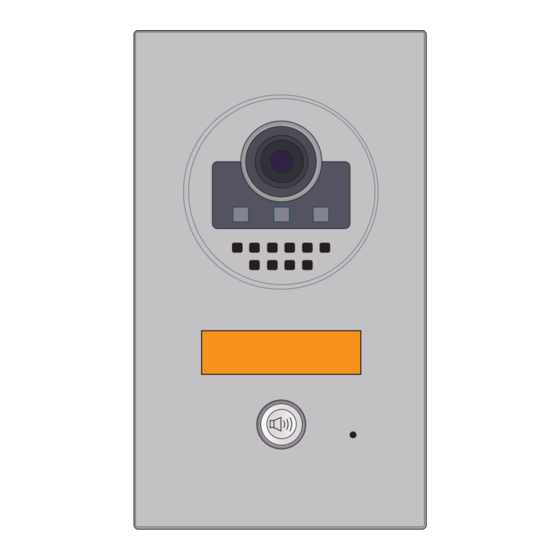
- Page 1 Door Station Model DT-597 2-wire series www.intelligenthomeonline.com...
-
Page 2: Parts And Function
Introduction This door station is equipped with a high resolution colour CCD camera sensor with wide angle of view 105 degrees. White LEDs enable the door station to work ef ciently at night. The door station facia is made of medical stainless steel 2.5 mm for better protection against vandalism and cauterization. -
Page 3: Door Station Mounting
Lock Control Jumper : To program electric lock type Door Station Code DIP : To program address for up to 4 x door stations T/R+,T/R- : USB-RS485 communication terminal Main Connect Port : To connect the bus line and electric locks (up to 2) BUS : Connect to the bus line, no-polarity PL : Additional power supply for the lock, connect to the power positive(power +) S1+ : The first lock power (+) output... -
Page 4: System Wiring And Connections
Replacing Name Label Steps: 1. Use the special spanner and move it 90 to loosen the screw 2. Open the front panel 3. Insert the new label System Wiring and Connections 1-Monitor Kit Connection monitor BUS PL S1+ S2+ S-... -
Page 5: Multi Door Stations Connection
Multi Door Stations Connection 4# Camera 3# Camera 2# Camera 1# Camera ID=11 ID=01 ID=10 ID=00 monitors BUS PL S1+ S2+ S- BUS PL S1+ S2+ S- BUS PL S1+ S2+ S- BUS PL S1+ S2+ S- 85~260VAC A B C D DBC-4 A Impedance switch... - Page 6 Multi Monitor Connection via Star with distributor DBC-4 (Models Cronus, Leda) monitor monitor 3 4 5 6 3 4 5 6 Impedance OFF ON switch Code=15, DIP-6=on Code=14, DIP-6=on monitor monitor 3 4 5 6 3 4 5 6 Code=12, DIP-6=on Code=13, DIP-6=on monitor monitor...
-
Page 7: Electric Lock Connection
Electric Lock Connection Up to 2 Electric or Magnetic locks can be connected and open independently. NOTE: both locks must be the same type, i.e. 2 x ‘Power-on-to-unlock’ or 2 x ‘Power-off-to-unlock’ Lock/s can be powered from door station if: 1. - Page 8 Connect one Lock Connect two Locks Take off the Jumper Take off the Jumper POWER POWER SUPPLY SUPPLY LOCK LOCK LOCK 5.2.3 ‘Unlock Mode’ parameter and Unlocking time programming via Monitor H/W : a1.3 S/W: V17.11.418.00 Manual Monitor Intercom Multimedia Local addr: Monitor Unlock timing:...
- Page 9 Door Station DIP Switches 2 x DIP switches used to set the address of door station if more than one connected into ON(1) OFF(0) the system Door station DIP switches setting Settings can be done either before or after installation DIP state Description Default setting, ID = 0(00), set to the first Door Station...
-
Page 10: Specifications
DIP state User code DIP state User code DIP state User code code=0 code=6 code=11 3 4 5 3 4 5 3 4 5 code=1 code=7 code=12 3 4 5 3 4 5 3 4 5 code=2 code=8 code=13 3 4 5 3 4 5 3 4 5 code=3... -
Page 11: Cables Requirements
Cables Requirements This system transmits video and audio through the power cable. No Polarity connection. Recommended cables Uncreened: twisted pair, flex multi-cores, speaker cable, CAT5/CAT6. Minimum requirements 0.5mm cable up to 2mm (depends on distance) monitor two or four monitors monitor monitor DBC-4... - Page 12 The design and specifications can be changed without notice to the user Right to interpret and copyright of this manual are preserved www.intelligenthomeonline.com...
Need help?
Do you have a question about the DT-597 and is the answer not in the manual?
Questions and answers