Table of Contents
Advertisement
Advertisement
Table of Contents

Related Manuals for 2easy DK1721


Summary of Contents for 2easy DK1721
- Page 1 2 WIRE INTERCOM SYSTEM DK1711-22 KIT Quick Guide RF CARD RF CARD Please read this manual carefully before using the product you purchase, and keep it well for future use.We reserve the right to modify the specification in this manual at any time without notice.
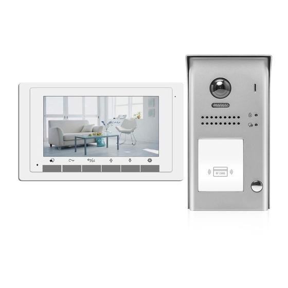
- Page 3 1* Relay- DS-ERL 1* AWG18 Power Cable 2* Management Cards- Add Card & Delete Card 5* Proximity Cards Kit DK1721/ID consists of 1* Outdoor Station- DT607C/ID-S1 2* Indoor Unit- DT17S 1* Power Supply with UL approved- DR-30-24 1* Power Separator- DT-DPS-DR...
-
Page 4: System Connection
2. System Connection Notes: [1] DT607C/ID-S1 (One button). The code address of indoor units start at 0-15 (switch all DOWN). [2] DT607C/ID-S2 (Two buttons) For the first button (from bottom to top), the code address of indoor units start at 0-15 (switch all DOWN). - Page 5 Two Apartment Connection (IN-OUT wiring) Code=16, DIP6=on 1 2 3 4 5 6 ID=0 Code=00, DIP6=off DR-30-24 L1 L2 PL S+ S- 1 2 3 4 5 6 Connecting Multi Indoor Monitors (IN-OUT wiring) Code=31, DIP6=on Code=30, DIP6=off Code=1, DIP6=off Code=0, DIP6=off 1 2 3 4 5 6 1 2 3 4 5 6...
- Page 6 Connecting Multi Indoor Monitors It can be star wiring (home run with distributor). Please note the distributor DBC4A(1) is not included in the kits. Code=00, DIP6=on Code=01, DIP6=on Code=16, DIP6=on Code=17, DIP6=on 1 2 3 4 5 6 1 2 3 4 5 6 1 2 3 4 5 6 1 2 3 4 5 6 ID=0...
-
Page 7: Parts And Functions
3. Parts and Functions Microphone LCD Screen Speaker Talk/Mon Button Setup Button Unlock Button Down/Decrease Button Call Button/ Up/Increase Button Unlock 2nd Button Mounting Hook Connection Port 1 2 3 4 5 6 Mounting Hook Key functions Item Description Microphone Receive voice from the user. -
Page 8: Terminal Description
Terminal description L1,L2: Bus line terminal. SW+,SW-: Extra door bell call button connection port. RING,GND: Extra buzzer connection 1 2 3 4 5 6 port. DIP switches: Total 6 bits can be configured. • Bit1~Bit5: User Code setting. • Bit6: Set to ON if the monitor is at the end of the line or works with DBC4A1. - Page 9 4. Terminal Description For Outdoor Station Lock Control Jumper: To select the lock type. Lock Control Jumper Motion Detector Connect Port: To connect external PIR motion detector. PIR Motion Detector Connect Port Main Connect Port: To connect the bus line and the electronic locks.
- Page 10 6. Settings Address Of Outdoor Station Factory default set at 0 1st station. Total 4 addresses can be configured. It can be modified either before or after installation. 0 is default, to change the setting, please follow the steps: ID=0,1 door station ID=1,2 door station...
- Page 11 7. Setting Unlock Mode For Outdoor Station There are 2 unlock modes, Normally opened (Factory default) and Normally closed. Normally opened is default, to change the setting, please follow the steps: In standby mode, press Press KEY_1 button to set Press KEY_1 button again KEY_SET button three the unlock mode to...
-
Page 12: Registering Id Card
9. Registering ID Card • Up to 320 user cards can be registered by the door station. • Easy management with LED status and sound hints. • There are two master cards, one MASTER CARD ADD card and one MASTER CARD DELETE card, When registered new master cards, the old master cards are invalid automatically. • Card reading distance is less than 3cm. • The master cards are necessary when you add or delete user cards. Please keep it well for future use. • EM card, 125kHz. Authorizing master cards: By default,there are two master cards marked MASTER CARD ADD and MASTER CARD DELETE ,but you should know that the master card can be authorized by users at any time. -
Page 13: Adding User Cards
Switching Access Control: The access can be controlled by door station or DT-ACC,so it’s available to switch the access function. Show the master card of MASTER CARD DELETE again to switch as a door station access control. UNLOCK Indicator:OFF TALK Indicator:OFF Show the master card of Show the master card of MASTER CARD ADD to ID MASTER CARD DELETE Buzzer Beep+... - Page 14 Deleting User Cards: Show the master card of Show user cards to be Show the master card of MASTER CARD DELETE to deleted in sequence. MASTER CARD DELETE ID card window in standby. again to exit. UNLOCK Indicator:ON UNLOCK Indicator:Blink one time UNLOCK Indicator:OFF TALK Indicator:OFF TALK Indicator:OFF...
- Page 15 10. Indoor Unit Parameter Setting How to enter the installation setting page (1) (2) (3) (4) 01.00 00.01.01 [0000] AUTO Six times Setting Setting 1.Press 2.Press 3.Press and hold 4.Use / button to increase button in standby button six times. Unlock button / decrease the value;...
- Page 16 DIP Switches Settings Of Indoor Unit The DIP switches are used to set the user code for each monitor.Total 6 bits can be config- ured. • Bit-1 to Bit-5 are used for user code setting. The value range is from 0 to 31, which have 32 different codes for 32 apartments.
-
Page 17: Answering A Call
11. Answering a Call 00:30 When there is a call from a video door station.The call tone sounds, an image will be displayed on the screen. TALK/MON button on the panel, begin communicating hands free with the Press visitor for 90 seconds. While communicating with the visitor, unlock the door, adjust volume / brightness / contrast are available. -
Page 18: Specification
2) Door Lock Controlled with External 1 2 3 Power Take off the jumper 1.The external power supply must be used according to the lock. 2.The inside relay contact is restricted to 230Vac 1A or 24Vdc 1A. 3.The jumper must be taken off before connecting. - Page 19 14. Hooking Up a Door Release -17-...
- Page 20 FOR TECHNICAL SUPPORT CALL 1516-387-6606 FROM 9AM TILL 4PM MONDAY THRU FRIDAY OUR WEBSITE WWW.NYWINT.COM DK1711-22 KIT The design and specifications can be changed without notice to the user. Right to interpret and copyright of this manual are preserved.
Need help?
Do you have a question about the DK1721 and is the answer not in the manual?
Questions and answers