Table of Contents
Advertisement
Quick Links
Advertisement
Table of Contents

Subscribe to Our Youtube Channel
Related Manuals for 2easy DK4761


Summary of Contents for 2easy DK4761
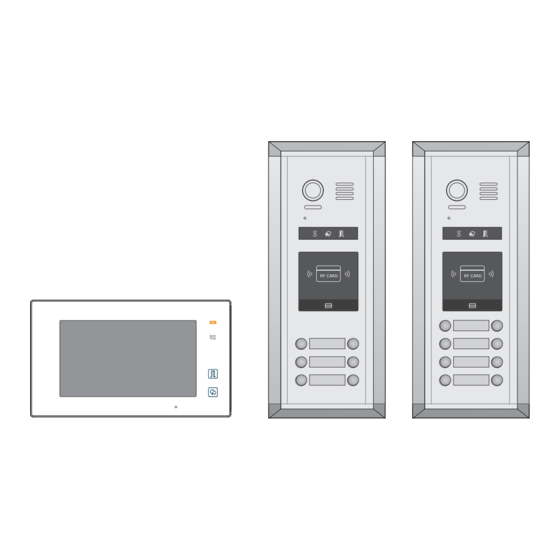
- Page 1 2 WIRE INTERCOM SYSTEM DK4761 & DK4781 Quick Guide RF CARD RF CARD Please read this manual carefully before using the product you purchase, and keep it well for future use.We reserve the right to modify the specification in this manual at any time without notice.
- Page 2 1. Product Lists Of Kits Kit DK4761 consists of : 1* Outdoor Station- DMR11S/ID/D6 1* Surface Box- RH-MR11 6* Indoor Units- DT47MG-W 2* Four Outputs Controller- DT-DBC4A1 1* Power Supply with UL approved- DR-30-24 1* Power Separator- DT-DPS 1* DIN Rail...
-
Page 3: System Connection
2. System Connection In-out wiring without any distributor [1]: Door Station, when there is only one Door Station, the DIP bit-1 and bit-2 should be set to 00. 3 4 5 6 Code=32, DIP-6=on [2]: Power Supply(DR-30-24), MUST be installed side by side with the DPS unit. - Page 4 Star wiring with 4 output distributor DBC4A1 3 4 5 6 3 4 5 6 Code=32, DIP-6=on Code=31, DIP-6=on Impedance OFF ON switch 3 4 5 6 3 4 5 6 Code=29, DIP-6=on Code=30, DIP-6=on 3 4 5 6 3 4 5 6 Code=3, DIP-6=on Code=4, DIP-6=on Impedance...
-
Page 5: Parts And Functions
3. Parts and Functions SD card [10] 1 2 3 4 5 6 Key functions Item Description See the next page for details Digital LCD touch screen Display the visitors' image Press it & hold for 3s to send SOS message to mo- Emergency button bile phone,the function is supported by GSM unit. -
Page 6: Terminal Description
Terminal description 1 2 3 4 5 6 DIP Switches 1 2 3 4 5 6 L1,L2: Bus line terminal. SW+,SW-: Extra door bell call button connection port. Ring,GND: Extra buzzer connection port. NC: Undefined. DIP switches: Total 6 bits can be configured. •... - Page 7 Speaker Camera Lens Night View LED Microphone 1 2 3 4 5 6 L1 L2 Status Indicator Connection ID Card Window port RF CARD LED Indicator Nameplate Call button 4.84 inch 4.17 inch Mounting box for Rainy cover for flush mounted surface mounted Note:Key A and key B will not be seen on the panel,they are cryptic.About activating key A and key B, please refer to Part 5.
- Page 8 5. DIP Switches Settings Of Outdoor Station Totally 6 bits can be configured by dip-switch. All ON(1) OFF(0) switches can be modified either before or after installation, please restarting the power whenever the switches have been modified. Bit definition Bit state Function Descriptions Default setting, ID = 0, setting for the first door station 3 4 5 6...
- Page 9 6. Indoor Unit Parameter Setting How to enter the installation setting page • On main menu page, touch [Logo] icon to enter About page. • When the screen stay in About page,press UNLOCK button on front panel and hold for 2 seconds. • A keypad is shown.
- Page 10 DIP Switches Settings Of Indoor Unit The DIP switches are used to set the user code for each monitor.Total 6 bits can be config- ured. • Bit-1 to Bit-5 are used for user code setting. The value range is from 1 to 32, which have 32 different codes for 32 apartments. • When multi monitors need to be installed in one apartment, these monitors should use the same user code, and the master/slave mode should be set on the monitor.
- Page 11 7. Call codes The door station automatically assigns the call codes to the connected module’s buttons. Regardless of the structure of the call button module, the button numbers are listed from the top to bottom and from left to right (in the case of double row buttons): In the case of double row buttons: RF CARD • DIP3 switch set to off...
-
Page 12: Answering A Call
8. Answering a call When there is a call from a video door station.The call tone sounds, an image will be displayed on the screen. Touch icon on screen or press TALK/MON button on the panel, begin communicating hands free with the visitor for 90 seconds. While communicating with the visitor, unlock the door, capture images/videos and adjust screen&volume are available. -
Page 13: Specification
Power-off-to-Unlock type: Power-off-to-Unlock type: 12V 300mA Cut off the line +12V LK - +12V LK - (GND) N.O. LK+(COM) N.O. Exit button Exit button 1 2 3 1 2 3 Jumper position in 1-2 Take off the Jumper JP_LK JP_LK 10. - Page 14 11. Hooking up a door release -13-...
- Page 15 Note -14-...
- Page 16 FOR TECHNICAL SUPPORT CALL 1516-387-6606 FROM 9AM TILL 4PM MONDAY THRU FRIDAY OUR WEBSITE WWW.NYWINT.COM DK4761 & DK4781 manual are preserved.
Need help?
Do you have a question about the DK4761 and is the answer not in the manual?
Questions and answers