Table of Contents
Advertisement
Installation Guide..........................................................................2
Modules. .......................................................................................4
Camera Module.........................................................................4
Keypad Module..........................................................................6
TFT Module. ...............................................................................11
Card Reader Module..................................................................12
Call Button Module ....................................................................14
Module Connection. ......................................................................16
CONFIGURATIONS......................................................................19
Common Door Station Setting ....................................................19
Software Update .........................................................................20
Tone Update ...............................................................................20
Namelist Update .........................................................................21
DMR21 TECHNICAL MANUAL
Apartment Intercom System
2-wire series
CONTENTS
DMR21/S8
1
2
5
6
9
0
A
RF CARD
DMR21/F2
DMR21/S4/F1
3
4
7
8
RF CARD
*
#
B
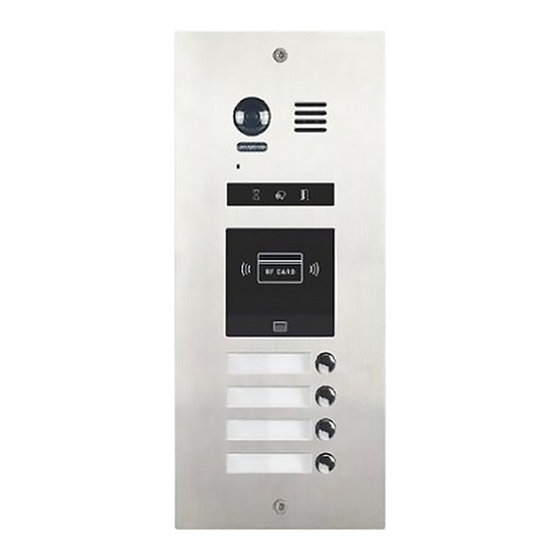
DMR21/D32/F1
RF CARD
DMR21/D8/F1
1
2
3
4
5
6
7
8
9
0
*
#
A
B
RF CARD
EP21/F3
EP21/S12
Advertisement
Table of Contents

Related Manuals for 2easy DMR21/D32/F1


Summary of Contents for 2easy DMR21/D32/F1
-
Page 1: Table Of Contents
TFT Module................11 Card Reader Module..............12 DMR21/S4/F1 DMR21/D8/F1 DMR21/S8 DMR21/D16 Call Button Module ..............14 Module Connection...............16 CONFIGURATIONS..............19 Common Door Station Setting ............19 Software Update .................20 RF CARD Tone Update ................20 RF CARD RF CARD Namelist Update .................21 DMR21/F2 DMR21/D32/F1 EP21/F3 EP21/S12... -
Page 2: Installation Guide
INSTALLATION GUIDE DESCRIPTION TERMINALS New generation Direct Call Apartments door stations are modular design with a flexibility to combine modules. For example,the video entry module can be assembled with card JP-LK CN/KMB CN/T-COIL 1 2 3 4 5 6 reader module and/or with keypad module. Additional combinations are available: TFT Screen Module with CN/FUN CN/WGN... -
Page 3: System Connection
INSTALLATION GUIDE MOUNTING SYSTEM CONNECTION Standard mounting Code=3 2 Code=3 1 Impedance OFF ON switch Code= 30 Code=2 9 Cut a hole and install the wall box Connect and plug bus line connector with cable Code= 8 Code= 7 Impedance OFF ON switch Code= 6... -
Page 4: Dip Switches Setting
INSTALLATION GUIDE 2) Door Lock Controlled with External Power DIP SWITCHES SETTING 1. The external power supply must be used according to the lock Totally 6 bits can be configured by dip-switch. The switches can be 2. The jumper must be taken off before connecting modified either before or after installation, but restarting the power is needed whenever the switches have been modified 3. -
Page 5: Modules
MODULES • Warning Tune Setting CAMERA MODULE When the door station with Camera Module in standby: 1. Parts and functions (1)Press and holld Key A for 3 seconds to enter the Warning Tune Option Mode, the Status indicator turns on and the current tune Speaker will be played Camera lens... -
Page 6: Keypad Module
MODULES KEYPAD MODULE • The example is set as cancel button and # as confirm button,please refer to */# function setting 1. Parts and functions for detail information • Forbid to slide to touch the digital keypad,it may cause mistaken key,the correct operation is using your finger to press the digit you desired Mounting •... - Page 7 MODULES Input the master code Beep+, Beep (Default: # 1.Reset all settings 2.Setting the master code 3.Setting the key 4.Setting the illumination time unlock time (Default 1234) (Default 10s) (Default 1s) Input the setting code. Input the setting code. Input the setting code. Input the setting code.
- Page 8 MODULES Input the master code Beep+, Beep (Default: # 5.Setting the unlock mode 6.Setting operation tone 7.Reset code setting 8. &# function setting (Default 0( O pened)) (Default ON) (Default Normal) Input the setting code. Input the setting code. Input the setting code. Input the setting code.
- Page 9 MODULES Input the master code Beep+, Beep (Default: # 9. Call tone setting 10.Interference resistant 11.SPK volume adjust 12.Night light level grade setting setting setting (Default enable) (Default 2) (Default:4) (Default 4) Input the setting code. Input the setting code. Input the setting code.
- Page 10 MODULES Input the master code Beep+, Beep (Default: # 16.Setting the code 17.Setting the code 18.Setting the code 19.Setting the code forTemporary1 forTemporary2 for user group1 for user group2 20~59 60~99 Input the setting code. Input the setting code. Input the setting code. Input the setting code.
-
Page 11: Tft Module
MODULES • Calling Display TFT DISPLAY MODULE This is the user interface of calling process. (Know that if the name list is created, the resident’s name will be showed on screen) 1. Parts and functions Press * (Keypad Module) to cancel the call. Mounting screw 3.5 inch TFT... -
Page 12: Card Reader Module
MODULES iii) When input admin code,a Setting Code will be asked on TFT CARD READER MODULE screen. 1. Parts and functions Mounting screw Swiping card area LED indicator • Combination with ID module When registered ID card will be presented to a Proximity Reader, “Door open”... - Page 13 MODULES • User Card Setting iii) Format Card In standby mode, show the MASTER CARD DELETE, it will sound Power on and short out EB+,EB- , a sound of “BP+” will be sent out, and the Unlock indicator will turn on “BP+,BP”, and the Unlock indicator will turn on i) Add User Card Show the MASTER CARD ADD, it will sound “BP+,BP”, and the Talk...
-
Page 14: Call Button Module
MODULES • Combination With Keypad Module CALL BUTTON MODULE 1. Parts and functions Mounting screw Call button Name plate Double row call button module Mounting screw 1) Master Card Setting(Reserve) Name plate 2) Add Card Setting(Reserve) Call button 2) Delete Card Setting(Reserve) Single row call button module • Combination With Keypad &... - Page 15 MODULES For single row of buttons • DIP3 switch set Off 4 5 6 RF CARD RF CARD • DIP3 switch set to on 4 5 6 RF CARD RF CARD 3. Address description Functions Call apartment 01 Call apartment 02 Call apartment 03 Call apartment 04 Call apartment 05...
- Page 16 MODULES CONNECTION • Card reader module TERMINAL DESCRIPTION • Video entry module INPUT OUTPUT Name Descriptions Name Descriptions JWGN1 Connect to CN/WGN of video entry module DIP switches for system configurations JKB' Connect to next call button module JP-LK For electronic lock safety type setting Connect to next call button module CN/KMB Call button module connection port...
-
Page 17: Dmr21/D16
MODULES CONNECTION CONNECTIONS • DMR21/D16 • DMR21/T4/D8 CN/KMB CN/KMB CN/FUN INPUT INPUT OUTPUT OUTPUT INPUT INPUT OUTPUT • DMR21/ID/S4 • DMR21/ID/KP CN/KMB CN/FUN CN/WGN CN/WGN INPUT INPUT OUTPUT OUTPUT INPUT INPUT RF CARD OUTPUT RF CARD DMR21 Technical Manual -17-... -
Page 18: Module Connection
MODULE CONNECTION • DMR21/S8+F3 INPUT CN/KMB CN/FUN CN/WGN OUTPUT INPUT INPUT OUTPUT OUTPUT INPUT INPUT OUTPUT OUTPUT RF CARD • DMR21/ID/KP INPUT CN/KMB CN/WGN OUTPUT INPUT INPUT OUTPUT OUTPUT INPUT INPUT RF CARD OUTPUT OUTPUT -18- DMR21 Technical Manual... -
Page 19: Configurations
CONFIGURATION 4.Calling COMMON DOOR STATION SETTING • Calling By Buttons 1.Namelist.txt file Setting: Press the call button to call corresponding monitors i) Create a TXT file, and named Namelist. ii) Open the Namelist.txt file, and input 5 [ ] symbols. Each [ ] symbol has its meaning, see the following picture. -
Page 20: Software Update
CONFIGURATIONS SOFTWARE UPDATE TONE UPDATE 1. Format SD card 1. Format SD card 2. Copy the Update DMR21.bin file to SD card by computer. 2. Copy the Update Ring.bin file to SD card by computer. 3.Update software: 3.Update ringtone: i) Power on the DMR21, and set DIP6 switch to ON, as the following i) Power on the DMR21, and set DIP6 switch to ON, as the following picture shows: picture shows:... -
Page 21: Namelist Update
CONFIGURATIONS NAMELIST UPDATE • Update by SD card 1. Format SD card 2. Copy the Update Namelist.bin file to SD card by computer. 3.Update namelist: i) Power on the DMR21, and set DIP6 switch to ON, as the following picture shows: DIP6=ON 1 2 3 4 5 CN/KMB...
Need help?
Do you have a question about the DMR21/D32/F1 and is the answer not in the manual?
Questions and answers