
Related Manuals for 2easy DT594


Summary of Contents for 2easy DT594
- Page 1 Door Station Model DT594 2-wire series This manual covers 1 and 2-Button Door stations www.intelligenthomeonline.com...
-
Page 2: Parts And Function
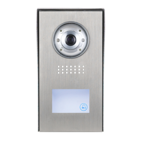
Introduction This door station is equipped with a high resolution colour CCD camera sensor, with a wide angle of view (105 ). White LEDs enable the door station to work efficiently at night. The door station facia is made of black plexiglass or stainless steel, with additional rain cover for better protection against water. -
Page 3: Door Station Mounting
Lock Control Jumper: To program electric lock type Door Station Code DIP: To program address for up to 4 door stations T/R+,T/R- : USB-RS485 communication terminal Main Connection Port: To connect the bus line and the electrick locks (up to 2) BUS (Blue&Green): Connect to the bus line, no-polarity PL (White): Additional power supply for the lock input, connect to the power positive(power +) -
Page 4: Adjusting Camera Angle
Do not mount door station close to the powerful light or exposed to the sunshine. It may cause over-exposed video Installation Steps: Installation height for door station approximately 145~160cm 1. Pic. 1 Use screws to mount the rain cover (if mounting with rain cover) to the wall. - Page 5 Multi Door Station Connection Maximum 4 Door Station can be connected. Requires an additional DBC4A Distributor 4# Camera 3# Camera 2# Camera 1# Camera ID=11 ID=01 ID=10 ID=00 monitors Bus PL S1+ S2+ S- Bus PL S1+ S2+ S- Bus PL S1+ S2+ S- Bus PL S1+ S2+ S- 85~260VAC DIP=on,off,off...
- Page 6 Multi Monitor Connection via Star (Models Cronus, Leda) Requires an additional DBC4A Distributor for every 4 x Video Monitors monitor monitor 3 4 5 6 3 4 5 6 Impedance OFF ON switch Code=15, DIP-6=on Code=14, DIP-6=on DIP=on,off,off monitor monitor 3 4 5 6 3 4 5 6 Code=12, DIP-6=on...
-
Page 7: Electric Lock Connection
Electric Lock Connection Up to 2 x Electric locks can be connected and opened independently. Note: both locks must be the same type, i.e. 2 of Power-on-to-unlock or 2 of Power-off-to- unlock Lock/s can be powered from Door Station if: 1. - Page 8 connect one lock connect two locks Take off the Jumper Take off the Jumper POWER POWER SUPPLY SUPPLY LOCK LOCK LOCK 5.2.3 Unlock parameter and Unlocking time programming (via Monitor) H/W : a1.3 S/W: V17.11.418.00 Manual Monitor Intercom Multimedia Local addr: Monitor Unlock timing: Video standard:...
- Page 9 Door Station DIP Switches 2 x DIP switches can be found on the right side if fascia of door station removed. Used to set the address of the door station if more ON(1) OFF(0) then one connected Door Station DIP switches setting Settings can be done either before or after installation DIP state Descriptions...
- Page 10 Bit state User code Bit state User code Bit state User code code=0 code=11 code=22 3 4 5 3 4 5 3 4 5 code=1 code=12 code=23 3 4 5 3 4 5 3 4 5 code=2 code=13 code=24 3 4 5 3 4 5 3 4 5 code=3...
-
Page 11: Cable Requirements
Cable Requirements This system transmits video and audio through the power cable. No Polarity connection Recommended cables: twisted pair, power flex multi-cores, speaker cable, CAT5/CAT6 Minimum requirements 0.5mm cable up to 2mm (depends on distance) monitor two or four monitors monitor monitor DBC-4 A... -
Page 12: Specification
Specification Power Supply : DC 24V (supplied by power supply) Power Consumption: Standby 60mA; Working status 200mA Camera: 1/4 ACS 4T image sensor with DSP processor Lock Power supply: 12Vdc, 300mA (Internal Power) Working temperature: -10ºC ~ +45ºC Dimensions: 188(H)×110(W)×34(D)mm The design and specifications can be changed without notice to the user.
Need help?
Do you have a question about the DT594 and is the answer not in the manual?
Questions and answers