Table of Contents
Advertisement
Quick Links
DESCRIPTION
The door stations are used as speaking and operating units for the
door communication system at the front door.Via the door station,a
call is connected to the desired home station after a call button is
pressed.
The DMR21 with the modular design ensures a high level of
flexibility,for example,the video entry module and the card reader
module can be assembled with call buttons outdoor station and the
user can swipe cards to open the door. For such combination,about
The keypad module can be assembled with call buttons outdoor sta-
tion, and users can enter the password to open the door,about the
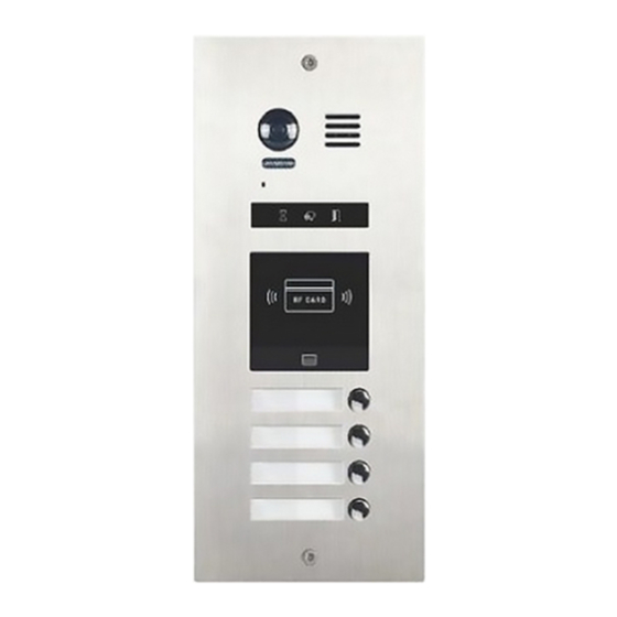
PARTS AND FUNCTIONS
Speaker
Camera Lens
Night View LED
Microphone
A
Status Indicator
ID Card Window
RF CARD
Nameplate
Call button
Screw hole
133 mm
Embedded box
Note:Key A and key B will not be seen on the panel,they are cryp-
tic.Normally,key A and key B are not activated,about the keys
activated,refer to the section of MODULES ->CAMERA MODULE.
-2-
INSTALLATION GUIDE
ON
DIP
B
1 2 3 4 5 6
Connection port
L1
L2
Stainless steel panel
TERMINAL
ON
DIP
JP-LK
1 2 3 4 5 6
CN/FUN
+12V: 12VDC power output.
LK-: Power ground.
LK+: Common contact of the relay.
NO.: Normally open contact of the relay(refer to DT technical guide
for Lock connection detail informations).
EB+: Exit button positive connection port.
EB-: Exit button negative connection port.
JP-LK: For electronic lock safety type setting(refer to door lock
connections).
SET :
CN/KMB: Call button module connection port.
CN/T-COIL: Reserved.
CN/FUN: Touch sensor keypad module or TFT display module con-
nection port.
CN/WGN: Card reader module connection port.
Bus(L1,L2): Non-polarity bus line,connect to PC6(power comb
unit).
PLACE NAMEPLATE
Press down and move right/left to open the transparent nameplate
cover. The insert the name paper and put the cover back. Note that
the double row button panel can be opened both direction, single row
button can only be opened at right side.
CN/KMB
CN/T-COIL
L1
L2
CN/WGN
name paper
DMR21 Technical Menu
Advertisement
Table of Contents

Subscribe to Our Youtube Channel
Related Manuals for 2easy DMR21


Summary of Contents for 2easy DMR21
- Page 1 JP-LK CN/KMB CN/T-COIL 1 2 3 4 5 6 The DMR21 with the modular design ensures a high level of flexibility,for example,the video entry module and the card reader CN/FUN CN/WGN module can be assembled with call buttons outdoor station and the user can swipe cards to open the door.
-
Page 2: System Connection
Drill a hole and attach the embedded box to it. Wire correctly and plug in the bus line connector RF CARD Note: the sketch map is taken DT47M monitor for example. Use the screws to fasten the panel The last view for all mounting. DMR21 Technical Menu... -
Page 3: Dip Switches Setting
Bit-3 is for single or double row button door station selection. If the Cut off the line Cut off the line door station is a double row button, such as DMR21-D8, set this bit to +12V +12V LK - (GND) LK - (GND) 0. -
Page 4: Camera Module
BP+, and the three Indicators will blink at the same time, for four times,that means the unlocking time is 4 seconds. that means the Restore Factory Setting is in progress; If the three Indicators turn off with a warning sound of BP+,it means the Restore Factory Setting DMR21 Technical Menu... -
Page 5: Keypad Module
Input the master code to switch to the setting mode, and input the cor- responding setting code to perform the settings for the function you want. After settings have been made, input the following setting codes to continue the setting operation. Press " " to exit the setting mode. DMR21 Technical Menu... - Page 6 DMR21 Technical Menu...
- Page 7 - When the operation tone is - When the item is set to 1,press set to 1,pressing the digital the # button to cancel the input, keypad will blink one time. and press the button to confirm the input . DMR21 Technical Menu...
- Page 8 Master code the “CALL” button. - The interference resistant (the LED turns white upon that) grade setting also will activate to activate the volume adjusting the keypad checking. function: Speaker adjustment: 3 (up), 6 (down). DMR21 Technical Menu...
- Page 9 - The user code can not be set the same as the master code and the sound of “beep,beep,beep,beep”,and the digitals you input before temporary code. will be cleared at the same time. - The temporary code can not be set the same as the master code -10- DMR21 Technical Menu...
-
Page 10: Tft Display Module
Press to select name. After that, press to call the corresponding user. ii) When in standby mode, press # key,a password will be asked. This is the user interface of password input. DMR21 Technical Menu -11-... -
Page 11: Card Reader Module
Show the ADD CARD, a sound of “BP+” will be sent out, the Unlock indicator is turned on. Show the DELETE CARD, a sound of “BP+” will be sent out, and all indicators will be turned off. After 10 seconds,it will exit out the Master Card Setting automatically. -12- DMR21 Technical Menu... - Page 12 It will sound “BP,BP+”, and all indicators are turned off. (without any Delete User Card etc. operation for 10 seconds, it will return to standby mode) For example,swipe the user card, the info of “Door Open” will be dis- played on screen. DMR21 Technical Menu -13-...
-
Page 13: Call Button Module
Combin With Keypad & TFT Module 2. Call codes The DMR21 automatically assigns the call codes to the connected module’s buttons. Regardless of the structure of the call button mod- ule, the button numbers are listed from the top to bottom and from... - Page 14 DIP3 switch set to on 4 5 6 RF CARD RF CARD 3. Address description Functions Call apartment 01 Call apartment 02 Call apartment 03 Call apartment 04 Call apartment 05 Call apartment 06 Call apartment 07 Call apartment 08 DMR21 Technical Menu -15-...
-
Page 15: Module Connection
OUTPUT Name Descriptions INPUT Connect to CN/KMB of video entry module OUTPUT Connect to next call button module Name Descriptions CN/FUN_IN Connect to CN/FUN of video entry module CN/FUN_OUT Connect to next keypad or TFT module -16- DMR21 Technical Menu... - Page 16 MODULE CONNECTION CONNECTIONS DMR21/D16 DMR21/T4/D8 CN/KMB CN/KMB CN/FUN INPUT INPUT OUTPUT OUTPUT INPUT INPUT OUTPUT DMR21/ID/S4 DMR21/ID/KP CN/KMB CN/FUN CN/WGN CN/WGN INPUT INPUT OUTPUT OUTPUT INPUT INPUT RF CARD OUTPUT RF CARD DMR21 Technical Menu -17-...
- Page 17 MODULE CONNECTION DMR21/S8+F3 INPUT CN/KMB CN/FUN CN/WGN OUTPUT INPUT INPUT OUTPUT OUTPUT INPUT INPUT OUTPUT OUTPUT RF CARD DMR21/ID/KP INPUT CN/KMB CN/WGN OUTPUT INPUT INPUT OUTPUT OUTPUT INPUT INPUT RF CARD OUTPUT OUTPUT -18- DMR21 Technical Menu...
-
Page 18: Common Door Station Setting
Calling By Buttons Press the call button to call corresponding monitors. has its meaning, see the following picture. Description: Button: DMR21 button which you need to set. Calling By Namelist Name: It will be displayed on TFT module. i) Press touch sensor button to show the name list. -
Page 19: Software Update
1. Format SD card 3.Update software: 3.Update ringtone: i) Power on the DMR21, and set DIP6 switch to ON, as the following i) Power on the DMR21, and set DIP6 switch to ON, as the following picture shows: picture shows:... -
Page 20: Namelist Update
CONFIGURATIONS NAMELIST UPDATE Update by SD card 1. Format SD card 3.Update namelist: i) Power on the DMR21, and set DIP6 switch to ON, as the following picture shows: DIP6=ON 1 2 3 4 5 CN/KMB CN/WGN INPUT ii) Insert SD card to slot.
Need help?
Do you have a question about the DMR21 and is the answer not in the manual?
Questions and answers