
Subscribe to Our Youtube Channel
Related Manuals for Liebert 30-130kVA


Summary of Contents for Liebert 30-130kVA
- Page 1 Npower ™ Operation & Maintenance Manual–30-130kVA, 60Hz, Single Module System AC Power For Business-Critical Continuity...
-
Page 3: Table Of Contents
MPORTANT AFETY NSTRUCTIONS ............2 VERVIEW ANUAL . - Page 4 Faults, Alarms, Status ............71 3.4.1 Faults .
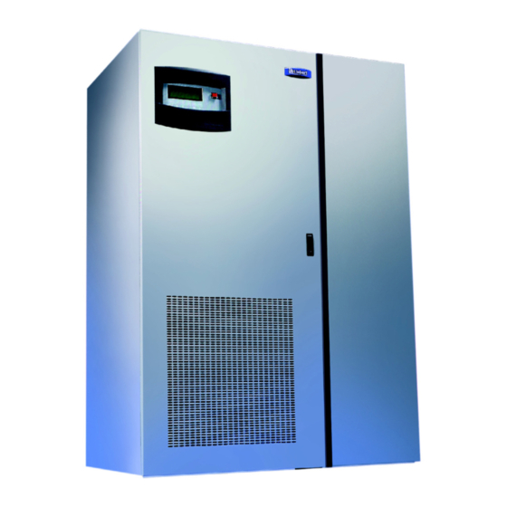
- Page 5 Figure 1 UPS controls and display screen (with example of the monitor/mimic screen)....6 Figure 2 80 kVA UPS outside and inside views ..........14 Figure 3 Operator control panel .
- Page 6 Figure 50 Options screen, page 1 ............43 Figure 51 10% passive filter settings screen .
- Page 7 Figure 100 Summary page screen............64 Figure 101 User settings, page 2.
-
Page 9: Save These Instructions
MPORTANT AFETY NSTRUCTIONS SAVE THESE INSTRUCTIONS. This manual contains important instructions that should be followed during maintenance of your Npower UPS and batteries. WARNING Exercise extreme care when handling UPS cabinets to avoid equipment damage or injury to personnel. Refer to separate installation manual for equipment handling information and installation procedures. -
Page 10: Overview O F Manual
Npower UPS, as well as the design princi- ples and standards that Liebert follows in the manufacture of each system. A description of the Npower system and an overview of its functions are also included. -
Page 11: Introduction
The system software allows the operator or Liebert Global Services to enter application specific infor- mation. Overload, overvoltage, battery discharge, and shutdown limits can be set by the operator. In effect, the software is tailored for each site. -
Page 12: Reliability
In addition, our Quality Assurance program is certified to the requirements of ISO 9001 standards. Liebert UPS systems are ETL listed to the requirements of UL 1778, CSA Certified and (when appli- cable) CE marked. All equipment and components are manufactured to applicable UL, NEC, IEC, EN, NEMA, ANSI, IEEE, EN50091-1, EN50091-2 and CSA standards and guidelines. -
Page 13: Modes Of Operation
NOTE If the UPS system has a blown fuse, the cause should be determined before you replace the fuse. Contact Liebert Global Services. Modes Of Operation Refer to 2.0 - Theory of Operation and 3.0 - Operation for more details. -
Page 14: Overload
Overloads in critical systems may be caused by inrush currents during connected equipment startup or by faults in the critical load or distribution network. The Liebert Npower UPS system can maintain full output voltage regulation while sustaining the following overloads: •... -
Page 15: Operator Controls
UPS system. The remaining options provide improved system performance or convenience. 1. Battery and Racks. The batteries provide power in the event of a power outage. The Liebert UPS can use a variety of battery types, provided the battery plant is designed for the UPS DC voltage range and the load requirements of your application. -
Page 16: Theory Of Operation
HEORY OF PERATION General Component Description The UPS system includes all of the equipment necessary to continuously provide computer- grade AC power to a critical load, even when there is an interruption of the utility line power. It consists of the UPS modules and a back-up battery plant. -
Page 17: Detailed Component Descriptions
Reporting information to a Liebert SiteScan Central Monitoring System. d. Relaying selected alarm messages to a Liebert Remote Alarm Status Panel and to a separate terminal board for customer use. e. Reporting key systems information via SNMP interface to a network monitoring system. -
Page 18: Rectifier/Charger
2.2.2 Rectifier/Charger The UPS module rectifier/charger consists of input fuses, AC current-limiting circuit, battery equalize charge circuit, DC filter, battery charge-current-limiting circuit, and bridge rectifiers. Operation The rectifier/charger converts the AC input power to DC power. This conversion is accomplished by 3- phase bridge rectifiers using SCRs. -
Page 19: Battery Disconnect
NOTE The manufacturers of the valve-regulated batteries supplied with Liebert’s standard battery cabinets recommend that when first installed the batteries be equalize charged. After that initial equalize charge, they recommend no further equalize charging for their batteries. Other manufacturers may have different recommendations for their products. -
Page 20: Static Bypass Switch
Theory of Operation Nonlinear Load Characteristics Computers and computer equipment with switching power supplies generate nonlinear currents rich in fifth and seventh harmonics. The inverter pulse-width-modulated waveform, coupled with the output filter, provides a natural path for reducing the fifth and seventh harmonic currents produced by the load. The inverter/filter limits the output voltage THD to less than 3% with up to 100% typical electronic data processing (EDP) loads. - Page 21 Transfer and Retransfer Conditions 1. Automatic Transfers to Bypass: Critical bus conditions that will initiate an automatic transfer of the critical load from the UPS inverter output to the bypass source are: a. Output Overload: overcurrent condition in excess of the current-versus-time overload capacity curve.
-
Page 22: Table 1 Key Locations On Ups
PERATION Operator Controls The Npower operator controls and indicators are located on the UPS Module Cabinet door and inside the cabinet. See Figure 2. The Operator Control Panel is located in the upper lefthand corner of the door, enabling the Operator to quickly identify the current status of the UPS system and to perform most of the manual operations. -
Page 23: Figure 3 Operator Control Panel
Figure 3 Operator control panel Table 2 Key locations on operator control panel Item Description Emergency Power Off Button Display Screen Navigation Buttons Function Turns power off in an emergency situation. Enables Operator to monitor power flow and meter readings, receive reports, and execute operational procedures. -
Page 24: Operator Control Panel
3.1.1 Operator Control Panel The Operator Control Panel enables the operator to perform the following tasks: • Obtain a quick indication of operational status: • Is the critical bus OK? • Is the UPS system OK? • Is the battery available? •... -
Page 25: Rotary Switch
Operator observe the light in the corner of the Rotary Switch panel before making any change. The switch position may be changed only if the light is green. Never move the switch if the light is red. Instead, call the Liebert Global Services technician. NOTE The LED light is positioned in the lower left-hand corner. -
Page 26: Security Access And Passwords
Security Access and Passwords Password protection is provided in the Npower UPS system to protect you from any unauthorized con- figuration of the system. A default password is installed on your system when you receive it.The default password is NPWR. It is important, however, that you enter your own secure password as soon as possible. -
Page 27: Display Screens And Procedures
Display Screens and Procedures The Operator Interface Display System of the Npower allows quick access to any screen the operator chooses. The default screen is the Mimic Display Screen. MENU TREE The figure below shows the primary screens that you can access through the Operator Interface Dis- play System. -
Page 28: Primary Screens
(constant) charge voltage. NOTE The manufacturers of the valve-regulated batteries supplied with Liebert’s standard battery cabinets recommend that when first installed the batteries be equalize charged. After that initial equalize charge, they recommend no further equalize charging for their batteries. Other manufacturers may have different recommendations for their products. -
Page 29: Mimic Display Screen
Main Menu Screen The Main Menu contains the primary menu selections that monitor and control the operation of the UPS. To access one of these screens, use the NAVIGATIONAL BUTTONS beneath the screen. First, press the UP or DOWN button until the desired screen is highlighted. Then press the SELECT button. -
Page 30: Figure 11 Mimic Display Screen Example: Utility Fail
In this example, power is available from the normal and bypass sources, as well as from the battery. Notice that the switching devices are all closed except for the bypass switch at the top. The load is operating on conditioned power from the inverter. The battery is being charged by the rectifier. The static switch is operative and ready to respond to momentary demands for overload current. -
Page 31: Figure 13 Monitor / Mimic Display Screen Example: Load On Bypass, Ups Module Off, Service Mode
In this example, the load is receiving power through the bypass switch. Notice that the input power source is available and the battery is being charged. Figure 13 Monitor / mimic display screen example: load on bypass, UPS module off, service mode In this example, the power is coming from the bypass source through the bypass switch to the load. -
Page 32: Figure 16 Dc Bus / Battery Status
Detailed Information Reports Detailed information reports are available through the following numbered blocks 1. INPUT STATUS. To access this screen, start with the Mimic Display Screen. Using the arrow keys, bracket INPUT and press SELECT. The screen displays the UPS input voltage and current as well as additional information. -
Page 33: Figure 17 Bypass Input Status
The DC BUS/BATTERY status screen displays the following real-time data: • DC Bus Volts • Battery Volts • Battery Current (Chg/disch) • Battery Temperature (This reading is the temperature of the ambient air in the battery cabinet.) • Battery Time Remaining 3. -
Page 34: Figure 19 Active Faults And Alarms Screen
The Output/Load status screen displays the following real-time data: • Output AC Volts AB, BC, CA • Output AC Volts AN, BN, CN • Output Current A, B, C • Output kVA, kW, A, B, C • Output Frequency • % rated kVA and kW •... -
Page 35: Startup
3.3.2 Startup There are two start up scenarios which can be followed depending on whether there is already power supplied to the UPS and the UPS is on Bypass, or there is no power to the UPS. Follow the appropri- ate instructions. -
Page 36: Figure 23 Startup / Shutdown Procedures Screen
Static Switch and you are clear to move the Rotary Switch to the NORMAL position and move on to Auto Startup on page 28. If the Static Switch contactors are not closed, repeat the above procedure. If this still does not close the static switch, contact Liebert Global Services for assistance. CAUTION If on Static Bypass, make sure the Static Switch is closed (Figure 22) before turning the Rotary Switch to normal. -
Page 37: Figure 25 Target And Ramp Values
Manual Startup On occasion, a service technician may wish to start the UPS manually while performing diagnostic testing. The manual startup, like the auto startup, requires that the Rotary Switch be in the NOR- MAL position. To start the system manually, highlight MANUAL STARTUP and press the SELECT button on the navigation bar. -
Page 38: Figure 27 External Maintenance Bypass Switch, Dual-Input Ups
An External Maintenance Bypass Switch can be added by Liebert or supplied by the Customer. The Liebert supplied option is outlined in Figure 27 and Figure 28 for the single input and dual input options, respectively. The rotary switch has three independent power contacts on a common shaft. A set of auxiliary contacts is incorporated into the shaft to determine the power switch position. -
Page 39: Table 3 External Maintenance Bypass Switch Positions And Actions
Figure 28 External maintenance bypass switch, single-input UPS UPS Input The table below summarizes the External Maintenance Bypass switch positions and actions. Table 3 External maintenance bypass switch positions and actions Switch position Maintenance (Service) Test (Bypass) On Line (Transition) On Line (Normal) When the External Maintenance Bypass switch is in Bypass or Maintenance position, the UPSC will assert the bypass contactor close signal and the output contactor open signal. -
Page 40: Table 4 External Maintenance Switch Configuration Options
External Maintenance Bypass Switch Configurations The External Maintenance Bypass Switch has three configuration options: • External maintenance bypass installed with interlock option • External maintenance bypass installed without interlock option • Not installed Table 4 External maintenance switch configuration options External Maintenance Switch Options... -
Page 41: Shutdown
3.3.3 Shutdown To shut down the UPS, navigate to the MAIN MENU, and select STARTUP/SHUTDOWN. This action will display the STARTUP/SHUTDOWN screen. From there, highlight USER SHUTDOWN and press SELECT. The following figure will appear. Figure 30 User shutdown screen The Operator can invoke two types of shutdowns from this interface screen: •... -
Page 42: Status Reports
The message Retransfer to UPS or Transfer to Bypass will appear depending on status of the critical load. The operator has two choices: Either to accept OK or EXIT. If a transfer or retransfer is not allowed, the FLASHING message Transfer Not Allowed is displayed. Press EXIT to return to the MAIN MENU. -
Page 43: Figure 34 Event Log Report Screen Showing Most Recent Event
Event Log The Event Log screen displays the faults, alarms, and status messages. Every message will have a time and date stamp. The Event Log is a sequence of messages or events captured in individual frames. See the following section on HISTORY LOGS for more information about frames. The following three screens show the last 3 in a series of 20 messages. -
Page 44: Figure 37 History Log Metering Report Screen
History Logs The History log contains pertinent data recorded just before and after an event that triggers a signifi- cant action such as an inverter failure.There are two History logs, each consisting of 64 frames. Each frame is a sequential snapshot of UPS-generated parameters. The UPS records these frames continu- ously at 4 millisecond intervals during normal operation. -
Page 45: Figure 38 History Log Status Report Screen
The second page is the STATUS, which includes: • Static Bypass Switch Line (Open/Closed) • Static Bypass Switch Load (Open/Closed) • Input Contactor (Open/Closed) • Output Contactor (Open/Closed) • Trap Filter (On/Off) (If installed) • Int. MBP (Normal/Bypass Service) • Ext. MBP (Open/Closed) •... -
Page 46: Configuration Screens
The Configuration Screens are used to set specific parameters or to view settings configured by the factory or Liebert Global Services (LGS). To access the System Configuration Screens, go to the Main Menu, move the highlighted cursor to SYSTEM CONFIGURATION, and press Select. -
Page 47: Figure 41 System Ratings, Page 1
System Ratings System rating parameters are normally entered by the factory or LGS. To get to the System Ratings screen, begin at the Main Menu. Using the arrow keys, move to Config- uration and press SELECT. This brings up the Configuration screen. (See Figure 40). From the Configuration screen, highlight System Ratings and press SELECT. -
Page 48: Figure 43 System Settings Screen
System Settings The System Settings are multiple screens that are used for setting the date, time, language, ID num- ber, Tag number and other parameters. The first page of the System Settings screen can be accessed by highlighting Systems Settings on the Configuration screen (Figure 40) and pressing SELECT. -
Page 49: Figure 46 System Settings, Page 2
Time To set the system's real time clock, do the following: 1. From the System Configuration screen, press the Up or Down button to move the highlighted cursor to TIME. 2. Press SELECT. The TIME screen will appear. 3. Press SELECT to move the arrow to the next digit to the right. 4. -
Page 50: Figure 47 System Settings, Page 3
Figure 47 System settings, page 3 SINGLE / DUAL INPUT OUTPUT TRANSFORMER BYPASS WIND. BYPASS AUTO TRANSFORMER OPTIONS . . . COMM. OPTIONS . . . The Single / Dual Input Screen is password protected. (See 3.2 - Security Access and Passwords for more information on Security Access and Passwords.) After highlighting Single / Dual Input from the System Settings Screen, and pressing SELECT, the following screen will appear. -
Page 51: Figure 50 Options Screen
Options This multiple-page screen, accessed from the third page of the SYSTEM SETTINGS screen, enables and disables optional features which might or might not be installed in your UPS. To enable or dis- able one of these options, do the following: 1. -
Page 52: Figure 52 Options Screen
Figure 52 Options screen, page 2 12 PULSE RECTIFIER BATTERY GND FAULT GREEN MACHINE FREQUENCY CONVERTER LINE DROP COMPENSATION NO Figure 53 Options screen, page 3 ALTERNATE POWER POLE FAN NO AUX. TEMP. MOTORIZED BATT. BREAKER BATT. CELL MONITOR Figure 54 Options screen, page 4 EXTERNAL MAINT. -
Page 53: Figure 55 Communication Options Screen
Communication Options Communication options are the various options that enable the operator to view data from remote locations and to program the type of data to be viewed. For detailed information, see Section 3.5 - Communication Interfaces. The communication options screens can be accessed from the third page of the System Settings screen. -
Page 54: Figure 59 Pager Support Configuration
To enable the modem, highlight INTERNAL or EXTERNAL and press SELECT. The Auto Dial screen will return (Figure 56) except instead of DISABLED, the message will read INTERNAL or EXTER- NAL. After enabling the modem, the Operator can proceed to configure Auto Dial settings at the AUTO DIAL screen. -
Page 55: Figure 60 Communications Options Screen
Figure 60 Communications options screen, page 2 Select NEXT to go to the Communication Options screen, third page. User Settings The User Settings are accessed from the Configuration Screen (Figure 40). Figure 61 User settings screen, page 1 NEXT Figure 62 User settings screen, page 2 NEXT COMMUNICATION OPTIONS REMOTE ALARM #2... -
Page 56: Figure 63 User Settings Screen
Figure 63 User settings screen, page 3 BATT. EOD RAMP START BATT. EOD RAMP END BATT. TEMP. ALARM LIMIT BATT. COMPARTMENT TEMP. LIMIT 50 INPUT PLL PHASE ADJUST NEXT Figure 64 User settings screen, Page 4 INPUT PLL SLEW RATE INPUT PLL SYNC RATE INPUT I LIMIT WALK-IN LCD CONTRAST... -
Page 57: Figure 66 10% Passive Filter Settings Screen
Highlighting 10% PASSIVE FILTER SETTINGS will bring up the following Operator--interactive screen. Figure 66 10% Passive filter settings screen Figure 67 User settings screen, page 6 AUTO RESTART SETTING ACTIVE FILTER ENABLE TEMPERATURE BATT. CB TRIP CHANGE PASSWORD INTERRUPTED TRANSFER ENABLE PREV. -
Page 58: Figure 69 Factory Settings Screen
Freeze This feature will freeze the History Log Buffer(s) if an alarm is detected. This feature is used mainly for diagnostic purpose by Liebert Global Services and Engineering. Event Logging The list of alarms that can be masked are shown in Table 7. Most Events are automatically logged into the Event History Buffer. -
Page 59: Figure 71 Alarm / Fault Name Screen
Delay This refers to the time in seconds that must occur before the UPS recognizes an alarm function. The delay can be anywhere from 0 to 99.9 seconds in 0.1 second intervals. If an alarm is set to Latch, it will only recognize the alarm and latch after the delay period. - Page 60 To change the programmable attributes, highlight the attribute to be edited and press the SELECT button. This action brings up a screen allowing the Operator to toggle between YES and NO. NOTE Some attributes cannot be edited. AUTO DIAL The Npower UPS can automatically dial (through the optional modem) each of two pre-programmed telephone numbers (up to 12 digits) when specified alarm conditions occur within the UPS system.
-
Page 61: Figure 73 Customer Alarm Interface Screen
Figure 73 Customer alarm interface screen CUSTOMER ALARM INTERFACE RELAY BOARD # 1 RELAY BOARD # 2 CONTACT BOARD If there is no board, the “NOT INSTALLED” message is displayed. 3. Pressing NEXT will bring up the second page. Figure 74 Customer alarm interface screen, page 2 REMOTE LED BOARD # 1... -
Page 62: Figure 76 Relay Assignments
To change the relay assignment, select RELAY ASSIGNMENTS from the screen and press SELECT. The following screen will appear. Figure 76 Relay assignments If you select STD SET, the following screen will be displayed. Figure 77 Programmable output relay board, standard set PROGRAMMABLE OUTPUT RELAY BOARD # 1 RELAY ASSIGNMENTS...STD SET PROGRAMMABLE RELAY # 1... -
Page 63: Figure 79 Programmable Output Relay Board, User Defined
If the Operator selects USER DEFINED from the RELAY ASSIGNMENTS screen, the following screen will come up. Figure 79 Programmable output relay board, user defined PROGRAMMABLE OUTPUT RELAY BOARD # 1 RELAY ASSIGNMENTS...USER DEFINED PROGRAMMABLE RELAY # 1 PROGRAMMABLE RELAY # 2 PROGRAMMABLE RELAY # 3 PROGRAMMABLE RELAY #4 All User Defined relays are programmable. -
Page 64: Manual Transfer
Navigating Protocol For the screen above and others like it, the normal screen navigation rules are changed. It is impor- tant to differentiate between the selections at the bottom of the display screen (UP/DOWN/ADD/ REMOVE/CLEAR/EXIT) and the navigation buttons or arrow keys below the display screen. To scroll up the Alarm/Fault list, use the arrow keys to highlight the UP selection at the bottom of the display screen. -
Page 65: Battery Management
Figure 82 Manual transfer / retransfer screen when transfer is not allowed BYPASS INVERTER INTERNAL BYPASS SWITCH EXT. MAINT. SWITCH INVERTER In the figure above, the message “TRANSFER NOT ALLOWED” will be flashing. 3.3.7 Battery Management The Battery Management screens display information on battery self tests, battery equalization, bat- tery temperature, and battery cycle monitoring. -
Page 66: Figure 85 Automatic Test Screen
The following conditions and features apply to either Auto or Manual Mode: • If you go to the battery screen, it will indicate “Battery Test in Progress”. When the test is com- plete, the indication “Last Battery Test” will either say “Battery Test Passed” or “Battery Test Failed.”... -
Page 67: Figure 86 Set Battery Cycle Screen
The Battery Equalizer Screen (Figure 88) will appear. CAUTION The manufacturers of the valve-regulated batteries supplied with Liebert’s standard battery cabinets recommend that when first installed the batteries be equalize charged. After that initial equalize charge, they recommend no further equalize charging for their batteries. -
Page 68: Figure 88 Battery Equalizer Screen
Figure 88 Battery equalizer screen AUTO MANUAL EQUALIZE TIME PERIOD EQUALIZE VOLTAGE From the Battery Equalizer Screen, you can choose one of the four options on the screen. The screens for these options are illustrated below. Figure 89 Auto screen AUTO MODE—When the battery recharge control logic is in the AUTO MODE, the UPS battery charger attempts the equalization process only if the EQUALIZE TIME PERIOD is greater than zero, the battery voltage has been at or below the Battery Discharging alarm limit for longer than 30 sec-... -
Page 69: Figure 91 Equalize Time Period Screen
Figure 91 Equalize time period screen When the battery is at full voltage (not being recharged), this selection reads EQUALIZE TIME PERIOD (hrs). When the battery is recharging, this selection reads EQUALIZE TIME REMAINING (hrs). After the equalize recharge time has expired, the indication returns to the preset equalize time. Figure 92 Equalize voltage screen The equalize voltage is also programmable. -
Page 70: Figure 94 Battery Temperature Compensation Enable/Disable Screen
To enable or disable the Battery Temperature Charge, highlight the top line in the screen above and press the SELECT button. This will bring up the following screen. Figure 94 Battery temperature compensation enable/disable screen To access page 2 of the Battery Temp Compensation Charge Screen, press NEXT on the Battery Temp Compensation Charge Screen (see Figure 93). -
Page 71: Figure 97 Battery Cycle Monitor Screen
The Operator can also erase the summary information as well, providing he inputs the proper password. However, this is not recommended for anyone except factory technicians or Liebert Service Engineers. Figure 98 Battery cycle monitor screen, page 2... -
Page 72: Figure 99 0-30 Seconds Discharge Cycles
Selecting the TIME button will display the time stamp of each cycle for three seconds after which it repaints the column with DATE stamps again. Figure 99 0-30 seconds discharge cycles 0 - 30 SECONDS DISCHARGE CYCLES DATE 04/26/01 02/09/01 TIME SUMMARY PAGE LAYOUT The Summary Page Screen is accessed from the Battery Cycle Monitor Screen. -
Page 73: Figure 101 User Settings, Page 2
BCM DATA DEFINITIONS / STORAGE At the start of every discharge cycle, Time and Date are recorded along with Battery Compartment Temperature in degrees C. While the cycle is in progress, the following data are stored: Lowest DC Bus Voltage, Battery KW Hours, and Highest Battery Discharge AMPS. At the end of the cycle. all of these parameters including Cycle Duration (in seconds), and Summary data including Accumulated Number Of Cycles, Accumulated Battery Amp Hours, and Accumulated Battery KW hours are stored. -
Page 74: Auto Restart
When the utility is restored, this feature directs an automatic restart, delivering the load power through the inverter, connecting the batteries to the DC bus, and recharg- ing the batteries. To utilize this feature, your system must have Liebert motorized Battery Breakers on each battery cabinet. -
Page 75: Figure 103Auto Restart Setting Screen
Figure 103Auto restart setting screen AUTO RESTART SETTING AUTO RESET TIMING The source qualification timer dictates how long to allow for input and bypass voltages to return to their nominal limits. The default value is 100 with a programmable range of 5-100 minutes. Since a setting of 100 signifies an infinite wait time, the finite range can be set between 5 and 99 minutes. -
Page 76: System Status Monitoring
3.3.9 System Status Monitoring In addition to the standard UPS metering and alarm information, Npower monitors and calculates other relevant data. This data can be accessed by starting from the Main Menu, selecting Status Reports, then System Status. The counters start from the time LGS or in special cases the contractor complete the startup proce- dure and customer accepts the system. -
Page 77: Figure 106System Status Screen
The condition for blackout occurs any time all 3 phases of the input voltage sources falls below 60% of the rated input voltage rating. The counter starts from the time the Liebert Global Services completes the startup procedure, and signs off the SYSTEM STATUS Screen. The counter is automatically re- enabled when all 3 phases of the input voltage source rise above the 60% limit. - Page 78 Operation Once the “UPS Sign Off” is acknowledged, it is stamped with RTC time and date. This step must be performed by LGS personnel. The software will keep track of the elapsed hours from that point on by subtracting the current time and date from the sign off time and date. Accumulated Operating Hours on UPS With output contactor closed and load KVA greater than 1%, software accumulates operating hours that the load is supported by UPS.
-
Page 79: Faults, Alarms, Status
Faults, Alarms, Status This section defines the active fault, alarm, and status indicators, their causes, and the associated system operations performed upon their detection. 3.4.1 Faults A fault is defined as an undesirable system operating condition that could cause further damage to the system or potentially drop the load. -
Page 80: Alarms
The following faults are detected by the UPS controls. Corrective actions, where possible, are auto- matic. • Active Filter Fail • Battery Overtemp CB Trip • Battery Ground Fault CB Trip • Bypass Power Supply Fail • EPO Shutdown • Heatsink Overtemp Limit • Input Power Supply Fail • Output Power Supply Fail •... -
Page 81: Figure 110 Summary Alarm Editing Screen
Highlight the SELECT position on the display screen to bring up the Summary Alarm Editing screen, allowing the Operator to edit the parameters of the summary alarm. Figure 110 Summary alarm editing screen LATCHING DIAL FREEZE EVENT LOG SAVE & EXIT CANCEL When the New Alarm, System Summary Alarm, or Module Summary Alarm is activated, you can get more information at the Operator Display Panel, through a remote terminal or a modem. -
Page 82: Table 7 Alarms, Functions, And Corrective Actions
Verify that input power is now available and restart the UPS following the instructions in this manual. If the system fails to restart properly contact Liebert Global Services. DC bus voltage is 15% or more over the nominal DC Bus Voltage. The UPS will transfer the load to Bypass and will shut down and isolate the UPS Module. - Page 83 This fault will inhibit startup. If fault persists check the bypass source for the cause of the frequency irregularity. Contact Liebert Global services if you have questions. With the load on Static Bypass the system has determined that at least one phase of the Bypass has exceeded the KVA, KW, or RMS current vs.
- Page 84 SBS to UPS. Remove the excess load from the UPS and attempt to re-start. If the load is below the rating of the UPS and it will not re-start, contact Liebert Global Services. One or more Output Fuses are open.
- Page 85 DPS sees its BGF input asserted by the SWGR. It will issue a batt breaker UV trip and motor op disable. To correct, repair and restart batt via the MM. Contact Liebert Global Services for assistance. With Bypass source available, the UPS has determined that the bypass power supply has failed.
- Page 86 Check the actual load against the UPS rating. Remove any excess load. Contact Liebert Global Services if the alarm persists. Failure of this fuse will remove control power. The UPS will attempt to transfer to Static Bypass if available.
- Page 87 The load automatically transfers to the bypass line. The UPS module is shut down and isolated. Contact Liebert Global Services at once. Do not attempt to reset the UPS. The Option Power Supply has failed.
- Page 88 Dual input systems will attempt to transfer to bypass if qualified and available. Call Liebert Global Services for Assistance. For all of these input problems the system will supply power from the battery until the end of discharge.
- Page 89 Static Bypass is inhibited. An interrupted transfer will be permitted only in the case of a critical fault. If this alarm persists, contact Liebert Global Services. One or more bypass voltages is below 80% or above 115% of the nominal value. If the load is on UPS, and the unit is a dual input unit, transfers to bypass will be inhibited.
- Page 90 Output frequency differs from the nominal (60Hz) by more than 0.5Hz. No transfer or shutdown occurs. Contact Liebert Global Services at once. With the load on UPS, Phase x output KVA or KW or RMS current has exceeded 105% of the nominal per phase rating.
- Page 91 If the manual transfer is inhibited, the Inverter may be latched off due to another fault. Contact Liebert Global Services. The UPS has determined that the actual number of Auto Retransfers in the past hour has exceeded the permitted maximum.
- Page 92 10 minutes. Check the air intake, air exhaust, and filters. Reduce the load or transfer it to bypass. Contact Liebert Global Services if the alarm persists. The intake air to the UPS module exceeds the specified maximum temperature. This...
- Page 93 If the alarm conditions are automatically corrected, reset the alarm to clear it. Contact Liebert Global Services if the alarm stays on. Shows after a successful transfer to Bypass. Display is only momentary.
- Page 94 (“Passed”) battery self test. The UPS has detected a communication failure between its UPS controls and it monitoring system. Contact Liebert Global Service. The User has initiated an “Inverter Off” or “System Shutdown” through the User Shutdown screen.
- Page 95 Table 7 Alarms, functions, and corrective actions (continued) Actual Alarm/fault Name Displayed Description Fault On Front of Alarm/ Panel Fault Alarm Auto Restart Auto Restart Alarm Failed Failed Auto Auto Rexfer Retransfer Alarm Primed Primed LBS Active LBS Active Alarm On Gen On Gen Active Alarm Active...
-
Page 96: Status
Table 7 Alarms, functions, and corrective actions (continued) Actual Alarm/fault Name Displayed Description Fault On Front of Alarm/ Panel Fault Alarm Input Contact Input Contact Alarm Input Contact Input Contact Alarm Input Contact Input Contact Alarm Input Contact Input Contact Alarm Input Contact Input Contact... -
Page 97: Table 8 Service Terminal Command Summary
3.5.1 RS-232 Port: Local Reporting Terminal The Npower transmits UPS system status and history information to a remote terminal through an RS-232 Port in ASCII Format. This feature is called the Service Terminal. The service terminal inter- face is intended to be accessed via PC terminal emulation software like Procomm Plus, Microsoft Win- dows Terminal or Hyperterminal, or directly through a standard ASCII terminal. -
Page 98: Requesting Information
Requesting Information If your Npower UPS is equipped with a modem and telephone line, you can call the UPS and receive system status and historical information. You can place the call from either a remote terminal or a personal computer with a communications program. Follow the instructions for your terminal or your communications program to call the UPS. -
Page 99: Remote Alarm Status Panel
CANBUS data link and Optional Power Supply to the Remote Alarm Status Panel. 3.5.4 SiteScan The SiteScan port sends UPS system information to a Liebert SiteScan Central Monitoring System. UPS operation, environmental control systems, and facility security can all be monitored from a sin- gle location. -
Page 100: Setting Up External Communication Devices
This section illustrates the flow of power through circuit breakers, switches, and UPS components dur- ing various modes of operation. The same modes of operation apply to all configurations of the Liebert Npower UPS. Highlighted (thick) lines in the diagrams indicate power flow and power availability. -
Page 101: Momentary Overloads
Alarm messages that indicate battery status are Battery Discharge, Low Battery, and Battery Shut- down. The voltage limits for these alarms are displayed on the UPS module Alarm Limit Settings screen. These limits were selected for your installation by Liebert Global Services during initial start- Figure 114 Utility fail, load on battery MIMIC DISPLAY RECT. -
Page 102: Automatic Operations
3.6.5 Automatic Operations The Npower UPS is designed to function while attended or unattended by an Operator. The system control logic monitors the performance of the UPS, the availability of power sources, and the current required by the critical load. Automatic UPS operations are described in the following sections. -
Page 103: Automatic Module Off Line
Automatic Module Off Line For specified UPS system faults, the control logic will initiate an automatic transfer to bypass fol- lowed immediately by a shutdown and isolation of the UPS system. All UPS contactors and the bat- tery circuit breaker are opened. The static bypass switch will close if the bypass line is available. Note that the bypass line is usually not available during Low Battery Shutdown. -
Page 104: Maintenance
Maintain the UPS cabinets free of foreign materials such as solder, wire cuttings, etc. Call Liebert Global Services if you are not sure of the procedures to follow or if you are not familiar with the design or operation of the equipment. -
Page 105: Routine Maintenance
If you have any doubt as to what must be done, call Liebert Global Services at 1-800-LIEBERT for further instructions. The UPS is designed for unattended operation, but does require some com- mon sense maintenance. -
Page 106: Battery Safety Precautions
NOTE Do not use equalize charging with valve-regulated lead-acid batteries, such as those used in Liebert Battery Cabinets. Consult the battery manufacturer's manual for specific information about equalize charging. Maintenance... -
Page 107: Torque Requirements
Refer to Battery Equalizer on page 59. Table 9 Battery voltage record Date * To be completed by Liebert Global Services customer engineer at time of start-up. 4.2.5 Torque Requirements All electrical connections must be tight. The next Table provides the torque values for the connections in the UPS. Use these values unless the equipment is labeled otherwise. -
Page 108: Detecting Trouble
If a problem occurs within the UPS, review all alarm messages along with other pertinent data. This information should be given via telephone to the Liebert Global Service dispatcher. This information can also be automatically sent by telephone modem. Call 1-800 Liebert to report a problem or to request assistance. - Page 109 Maintenance NOTES...
- Page 110 Maintenance...
- Page 112 © 2006 Liebert Corporation All rights reserved throughout the world. Specifications subject to change without notice. ® Liebert and the Liebert logo are registered trademarks of Liebert Corporation. All names referred to are trademarks or registered trademarks of their respective owners.
Need help?
Do you have a question about the 30-130kVA and is the answer not in the manual?
Questions and answers