Table of Contents
Advertisement
Quick Links
Advertisement
Table of Contents
Troubleshooting

Related Manuals for Liebert Vertiv GXT5


Summary of Contents for Liebert Vertiv GXT5
- Page 1 Vertiv Liebert® GXT5 UPS 230 V Input, 230 V Output Installer/User Guide...
- Page 2 The information contained in this document is subject to change without notice and may not be suitable for all applications. While every precaution has been taken to ensure the accuracy and completeness of this document, Vertiv assumes no responsibility and disclaims all liability for damages resulting from use of this information or for any errors or omissions.
-
Page 3: Table Of Contents
1.8.5.Maintenance Bypass Mode ....................................22 Chapter 2: Installation ..................................23 2.1. Unpacking and Inspection ......................................23 2.2. Pre-installation Preparation .....................................24 2.2.1. Installation Clearances ......................................24 2.3. Installing the UPS..........................................25 2.3.1. Tower Installation ........................................25 2.3.2. Rack Installation ........................................26 Vertiv | Liebert® GXT5™ | Installer/User Guide... - Page 4 3.1. Silencing the Audible Alarm .......................................47 3.2. Starting-up the UPS .........................................47 3.3. Transferring to Battery Mode ....................................50 3.4. Transferring from Normal to Bypass Mode ............................. 50 3.5. Transferring from Bypass to Normal Mode ............................. 50 Vertiv | Liebert® GXT5™ | Installer/User Guide...
- Page 5 4.3.4.Setting the Date and Time ...................................79 Chapter 5: Maintenance ................................81 5.1. Replacing Batteries ........................................81 5.2. Charging Batteries........................................85 5.3. Checking UPS Operation ...................................... 86 5.4. Cleaning the UPS ......................................... 86 5.5. Replacing the Power-distribution Box ..............................86 Vertiv | Liebert® GXT5™ | Installer/User Guide...
- Page 6 6.2. Audible Alarm (Buzzer) ......................................101 6.2.1.Faults............................................102 6.3. Troubleshooting UPS Issues ...................................102 Chapter 7: Specifications .................................105 7.1. Battery Run Times ........................................118 Appendix I: Open Source Software Legal Notices ..................125 Appendix II: Technical Support ............................127 Vertiv | Liebert® GXT5™ | Installer/User Guide...
-
Page 7: Important Safety Information
IMPORTANT! This manual contains important safety instructions that must be followed during the installation and maintenance of the UPS and batteries. Read this manual thoroughly and the safety and regulatory information, available at https://www.vertiv.com/ComplianceRegulatoryInfo, before attempting to install, connect to supply, or operate this UPS. Vertiv | Liebert® GXT5™ | Installer/User Guide... - Page 8 This page is intentionally left blank. Important Safety Information...
-
Page 9: Ups Features And Available Models
Chapter 1: GXT5 Description The Liebert® GXT5 is a compact, online uninterruptible power system (UPS) that continuously conditions and regulates its output voltage. The Liebert® GXT5 supplies microcomputers and other sensitive equipment with clean sine-wave input power. Upon generation, AC power is clean and stable. However, during transmission and distribution it is subject to voltage sags, spikes, and complete failure that may interrupt computer operations, cause data loss, and damage equipment. -
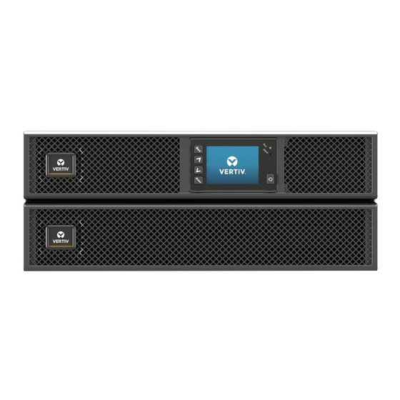
Page 10: Front Panels
MODEL NUMBER NOMINAL POWER RATING @ 230 V INPUT GXT5-3000IRT2UXL* 3000 VA/3000 W GXT5-3000IRT2UXLE GXT5-3KL620RT2UXL 3000 VA/2700 W GXT5-3KL630RT2UXL 3000 VA/3000 W GXT5-5000IRT5UXLN* GXT5-5000IRT5UXLE 5 kVA/5 kW GXT5-5000HVRT5UXLN* GXT5-8000IRT5UXLN* GXT5-8000IRT5UXLE 8 kVA/8 kW GXT5-8000HVRT5UXLN* GXT5-10KIRT5UXLN* GXT5-10KIRT5UXLE 10 kVA/10 kW GXT5-10KHVRT5UXLN* GXT5-16KIRT9UXLN* 16 kVA/16 kW GXT5-16KIRT9UXLE... -
Page 11: Chapter 1: Gxt5 Description
Programmable C13 output receptacles C14 input-power plug and cable Terminal block/communication connectors RS-232 port - RJ-45/RJ-11 connection used for command line interface RS-485 port - RJ-45 connection used for external temperature sensors USB port Vertiv | Liebert® GXT5™ | Installer/User Guide... - Page 12 Figure 1-3 GXT5-1500IRT2UXL (XLE) Rear Panel ITEM DESCRIPTION Liebert® IntelliSlot™ port Ventilation Hole External-battery-cabinet connector Input circuit-breaker reset button, 10-A Non-programmable C13 output receptacles Programmable C13 output receptacles C14 input-power plug and cable Terminal block/communication connectors RS-232 port - RJ-45/RJ-11 connection used for command line interface...
- Page 13 C20 input-power plug and cable Input circuit-breaker reset button, 16-A Terminal block/communication connectors RS-232 port - RJ-45/RJ-11 connection used for command line interface RS-485 port - RJ-45 connection used for external temperature sensors USB port Vertiv | Liebert® GXT5™ | Installer/User Guide...
- Page 14 Figure 1-5 GXT5-3000IRT2UXL (XLE) Rear Panel ITEM DESCRIPTION Liebert® IntelliSlot™ port Ventilation Hole External-battery-cabinet connector Non-programmable C19 output receptacle Output circuit-breaker reset buttons, 10-A Non-programmable C13 output receptacles Programmable C13 output receptacles C20 Input-power plug and cable Input circuit-breaker reset button, 20-A...
- Page 15 Programmable output circuit breaker, 10-A (x2) Output circuit breaker - Controls terminal block output and non-programmable output receptacles Maintenance bypass breaker Removable junction box with cable entry for hard-wire I/O Input circuit breaker Vertiv | Liebert® GXT5™ | Installer/User Guide...
- Page 16 Figure 1-7 GXT5-8000/10KIRT5UXLN (XLE) Rear Panel ITEM DESCRIPTION Liebert® IntelliSlot™ port Terminal block communication connectors USB port RS-485 port - RJ-45 connection used for external temperature sensors RS-232 port - RJ-45/RJ-11 connection used for command line interface REPO connector DB9 ports - Used for communication when operating in a parallel system See Section 2.8.
- Page 17 DB9 ports - Used for communication when operating in a parallel system See Section 2.8. Installing a Parallel System Input circuit breaker Bypass circuit breaker Knock-outs/cable-entry for hard-wire I/O Output circuit breaker POD breaker Cover for optional POD-installation location External-battery-cabinet connector Vertiv | Liebert® GXT5™ | Installer/User Guide...
-
Page 18: Removable Power Distribution Box
1.4. Removable Power Distribution Box The 16-kVA and 20-kVA models do not ship with an installed power-distribution box (POD). The optional PODs for the 16-kVA and 20-kVA models are: • PD2-108 for models ending in "N" only (North America) • PD2-200 •... -
Page 19: Internal Battery Packs
UPS. 3-kVA and below units have 1 battery pack, 5-kVA and 10-kVA units have 2 battery packs, and 16-kVA to 20-kVA units have 4 battery packs.. Figure 1-11 Internal Battery Pack ITEM DESCRIPTION Handle Connector Vertiv | Liebert® GXT5™ | Installer/User Guide... -
Page 20: Battery Cabinet
1.6. Battery Cabinet Optional battery cabinets are available for the UPS, and include a single battery-connector cable. Up to 10 battery cabinets can be connected in parallel to the UPS, and up to 6 can be detected using EBC - detection. Table 7-8 page 116 Table 7-9... - Page 21 5 kVA and 6 kVA models 8 kVA and 10 kVA models 16 kVA and 20 kVA models Vertiv | Liebert® GXT5™ | Installer/User Guide...
-
Page 22: Major Internal Components And Operating Principle
Table 1-2 Major Components (For 0.75 kVA to 3 kVA) ITEM COMPONENT OPERATION/FUNCTION Transient Voltage Surge Provide surge protection. Filter electromagnetic interference (EMI) and radio Suppression (TVSS) and frequency interference (RFI). Minimize surges or interference present in the EMI/RFI Filters utility power and protect devices connected on the same branch as the UPS. - Page 23 Maintenance bypass keeps connected equipment powered with unility Maintenance bypass power and allows replacement of the UPS in the event of a UPS malfunction. Outlet group Output receptacles and terminal block. Programmable output Output receptacles Vertiv | Liebert® GXT5™ | Installer/User Guide...
-
Page 24: Maintenance Bypass
Table 1-4 Major Components (For 16 kVA to 20 kVA) ITEM COMPONENT OPERATION/FUNCTION Transient Voltage Surge Provide surge protection. Filter electromagnetic interference (EMI) and radio frequency interference (RFI). Minimize surges or interference present in the Suppression (TVSS) and utility power and protect devices connected on the same branch as the UPS. EMI/RFI Filters Regulates input AC power to continuously float-charge the batteries. -
Page 25: Ups States And Operating Modes
(green) is ON, the alarm indicator is OFF, and the buzzer is silent. shows the diagram of normal mode. Figure 1-14 Normal-mode Operation ITEM DESCRIPTION Mains/Utility input (by-pass input) Rectifier/PFC Inverter Battery charger Battery Bypass static switch UPS output Vertiv | Liebert® GXT5™ | Installer/User Guide... -
Page 26: Bypass Mode
1.8.2. Bypass Mode Bypass mode supplies power to the load from the bypass source (utility power) if an overload or fault occurs during normal operation. On the front-panel display, the run indicator (green) is ON, the alarm indicator (yellow) is ON, and the buzzer beeps once each seconds. The LCD “Flow” screen displays “On Bypass.” Figure 1-15. -
Page 27: Battery Mode
• If utility power fails and the batteries are charged, you may cold-start the UPS in battery mode and use battery power to extend system availability for a time. Figure 1-16 Battery-mode Operation ITEM DESCRIPTION Mains/Utility input (by-pass input) Rectifier/PFC Inverter Battery charger Battery Bypass static switch UPS output Vertiv | Liebert® GXT5™ | Installer/User Guide... -
Page 28: Eco Mode
1.8.4. ECO Mode The energy-saving ECO mode reduces power consumption by powering the load via bypass if the bypass voltage is normal or by powering the load via the inverter when the bypass voltage is abnormal. You can use ECO mode to power equipment that is not sensitive to power-grid quality via bypass which reduces the power consumption. - Page 29 Figure 1-17 Maintenance Bypass-mode Operation ITEM DESCRIPTION Mains/Utility input (bypass input) Rectifier/PFC Inverter Battery charger Battery Bypass static switch UPS output Maintenance bypass Vertiv | Liebert® GXT5™ | Installer/User Guide...
- Page 30 This page is intentionally left blank. GXT5 Description...
-
Page 31: Chapter 2: Installation
• Check the accessories included against the packing list. If there is any discrepancy, contact your local Vertiv representative immediately. Liebert GXT5 UPS - AP Packing list includes the following items (750 VA to 3000 VA): • Terminal block communications terminal • For 750 VA - 1500 VATION •... -
Page 32: Pre-Installation Preparation
Liebert GXT5 UPS - AP Packing list includes the following items (5 kVA to 10 kVA): • Terminal block communications terminal • Mounting rail kit (not included with “E” models) • Liebert IntelliSlot Unity card (RDU101), factory • Power-distribution box (POD), installed on GXT5 installed (not included with “E”... -
Page 33: Installing The Ups
ITEM DESCRIPTION Support bases Spacers with connectors 2. If optional, Liebert® external battery cabinets will be connected, take out the spacers shipped with the battery cabinet. 3. Connect the spacers and the support bases as shown in Figure 2-1 above. Each GXT5 requires 2 support bases, one in the front and one in the rear. -
Page 34: Rack Installation
2.3.2. Rack Installation When installed in a rack enclosure, the GXT5 UPS and external battery cabinets (EBC) must be supported by a shelf or rack-mount rails. Because different rack-mount options install in various ways, refer to the installation instructions provided with the rack-mount kit. CAUTION The GXT5 is heavy. - Page 35 • When removing an EBC, turn off the circuit breaker on the rear of the cabinet before disconnecting the cable. • If shipping or storing the UPS for an extended time, disconnect the EBC(s) to minimize stand-by current drain on the batteries which help to maintain design life. Vertiv | Liebert® GXT5™ | Installer/User Guide...
- Page 36 Figure 2-2 EBCs connected to the 5/6 K UPS ITEM DESCRIPTION EBC-detection dry-contact port (See Table 2-3 page 33, for details.) EBC connector EBC-detection port External battery cabinet External battery cabinet Installation...
-
Page 37: Installing A Power Distribution Box
Off and wear appropriate, OSHA approved personal protective equipment (PPE) per NFPA 70E. Failure to comply can cause serious injury or death. Before proceeding with installation, read all instructions. Follow all local codes. Vertiv | Liebert® GXT5™ | Installer/User Guide... - Page 38 The 5-kVA to 10-kVA models ship with a removable power-distribution box (POD) installed, see Terminal-block Connections page 33, to make the electrical connections to the UPS. For removal, see the appropriate procedures in Maintenance page For 16-kVA to 20-kVA models, the POD ships separately and must be attached to the rear of the UPS. See Removable Power Distribution Box page 12, for the POD options compatible with your GXT5 model.
-
Page 39: Hardwired Input/Output Connections
3.5mA. However in the practical application environment the earth leakage current by the UPS cannot be predicted or quantified due to external supply perturbations. Therefore, we do not recommend the use of an MCB with ELC protection upstream of UPS. Vertiv | Liebert® GXT5™ | Installer/User Guide... - Page 40 Table 2-2 Branch circuit breaker rating UNIT RATING RECOMMENDED BREAKER RATING 750 VA 1000 VA 10 A 1500 VA 2000 VA 16 A 3000 VA 20 A 5 KVA 40 A 6 KVA 50 A 8 KVA 63 A 10 KVA 1-phase: 140 A 16 KVA 3-phase: 50 A...
-
Page 41: Terminal-Block Connections
2. Referring to the appropriate terminal-block connection instructions, connect the cables to the corresponding input/output terminals and use a torque wrench to turn the screw clockwise until tightened as specified in Table 2-3 above. Vertiv | Liebert® GXT5™ | Installer/User Guide... -
Page 42: Connecting To Terminal Blocks On 5-Kva And 6-Kva Model
• Connecting to Terminal Blocks on 5-kVA and 6-kVA model page • Connecting to Terminal Blocks on 8-kVA and 10-kVA models page • Connecting to Terminal Blocks on 16-kVA and 20-kVA models page 35 3. Re-install the cable-entry/conduit-box cover, and tighten the screws. 2.6.3. -
Page 43: Connecting To Terminal Blocks On 16-Kva And 20-Kva Models
1-in 1-out common-source connection Figure 2-8 3-in 1-out split-bypass connection ITEM DESCRIPTION Output Bypass Input Figure 2-9 3-in 1-out Common-source Connection, 16-kVA and 20-kVA models ITEM DESCRIPTION Output Bypass Input Shorting cable (W01), installed at factory Vertiv | Liebert® GXT5™ | Installer/User Guide... - Page 44 Figure 2-10 1-in 1-out Split-bypass Connection, 16-kVA and 20-kVA models ITEM DESCRIPTION Output Bypass Input Shorting cable (W02), included with accessories Figure 2-11 1-in 1-out Common-source Connection, 16-kVA and 20-kVA models ITEM DESCRIPTION Output Bypass Input Shorting cable (W03), included with accessories Installation...
-
Page 45: Communication Connections
• We recommend that signal-cable lengths be less than 10 ft (3 m), and are kept away from power ca- bling. 2.7.1. Connecting IntelliSlot Communication This Liebert® RDU101 card communicates with Building Management Systems via SNMP and LIFE/Remote Services. See the appropriate figure for your model in... - Page 46 Figure 2-12 Dry-contact Port and Pin Layout • Pins 7 and 8 are shorted before delivery. • The emergency power-off (EPO) action of the UPS closes the rectifier, inverter and static bypass, but it cannot disconnect the UPS mains input inside. To completely disconnect the UPS, disconnect the upstream input circuit breaker when generating the EPO.
- Page 47 Pins 11 and 12 are shorted when the fault occurs. When NC, Pins Output 6 11, 12 Remote Fault Alert 6 11 and 12 are opened when the fault occurs. Options are: • Low battery • On battery • On bypass • UPS fault (default) Vertiv | Liebert® GXT5™ | Installer/User Guide...
-
Page 48: Connecting A Remote Emergency Power-Off (Repo) Switch
2.7.3. Connecting a Remote Emergency Power-off (REPO) Switch The UPS includes an EPO connection in the dry-contact port. See the appropriate figure for your model in Rear Panels page 5, for the location of the port. UPS ships with a REPO jumper installed, allowing the UPS to operate as a normally-closed switch system (fail- safe). -
Page 49: Connecting A Usb Cablex
The RJ-45 port (labeled “R232”) is used for CLI connection. See the appropriate figure for your model in Rear Panels page 5, for the location of the port. The pin-out, described in below table is consistent with the ACS pin-out. ITEM DESCRIPTION TXD (out) RXD (in) Vertiv | Liebert® GXT5™ | Installer/User Guide... -
Page 50: Connecting Liebert Irm Sensors
2.7.6. Connecting Liebert IRM sensors The GXT5 supports up to 40 Liebert® IRM sensors (The sensor address must be 1~40). Available sensor types include temperature, and temperature & humidity sensors. The highest sensor data can be shown in GXT5/battery status page. And the highest temperature from the sensors can be used for battery temperature compensation. - Page 51 CAUTION!Risk of improper disconnection Can cause equipment damage. Do not disconnect parallel-system cables while the system is operating. Figure 2-14 Connection of 2 + 1 Parallel System ITEM DESCRIPTION Upper connector Lower connector Vertiv | Liebert® GXT5™ | Installer/User Guide...
-
Page 52: First-Time Start-Up Of A Parallel System
2.8.1. First-time Start-up of a Parallel System IMPORTANT Do not start the UPS until after the installation is finished, the system is commissioned by an authorized engineer, and the external input circuit breakers are closed. CAUTION Starting the UPS applies mains/utility power to the output terminals. Make sure that the load power is safe and ready to accept power. -
Page 53: Commissioning Parallel System
3. At any other UPS in the system, update the parallel parameters as follows: • On the display, press Enter to display the Main Menu, then use the arrow buttons to select Settings, and press Enter. Vertiv | Liebert® GXT5™ | Installer/User Guide... - Page 54 • Use the arrow buttons to select the Parallel tab, then press Enter to display the parameters list. • Set the system count from N to N + 1, and then use last item in the list, Sync parallel parameters. •...
-
Page 55: Chapter 3: Operating The Ups
Use the Up/ Down arrows to select YES, then press Enter. 8. If this is the first-time start-up of the UPS, the Start-up Guidance wizard opens to set the basic parameters of the UPS. Follow the prompts. Vertiv | Liebert® GXT5™ | Installer/User Guide... - Page 56 Start up Guidance(1/4) Start up Guidance(2/4) Start up Guidance(3/4) Operating the UPS...
- Page 57 Start up Guidance(4/4) For detailed description of UPS display functions and settings, see Operation and Display Panel page Vertiv | Liebert® GXT5™ | Installer/User Guide...
-
Page 58: Transferring To Battery Mode
3.3. Transferring to Battery Mode The UPS operates in Normal mode unless the mains/utility power fails or it is performing a battery self test, then it automatically transfers to Battery mode for the back-up time available or the mains/utility power is restored. -
Page 59: Shutting-Down The Ups Completely
To manually power-off in an emergency, disconnect the terminal connecting the REPO port on the rear of the UPS. If mains/utility power is present, the UPS control circuit remains active even though output power is disabled. To remove all mains/utility power, disconnect the external main-input circuit breaker. Vertiv | Liebert® GXT5™ | Installer/User Guide... - Page 60 This page is intentionally left blank.
-
Page 61: Chapter 4: Operation And Display Panel
Run indicator LED, see LED Indicators page Alarm indicator LED, see LED Indicators page Power button, see Table 4-1 on the next page. Menu keys, see Table 4-1 on the next page. LCD panel. Vertiv | Liebert® GXT5™ | Installer/User Guide... -
Page 62: Led Indicators
Table 4-1 Display-panel Button Functions and Descriptions BUTTON FUNCTION DESCRIPTION Enter Confirm or enter selection. Move to next page, increase value, move left for Tower model, and move right for Rack model. Down Move to previous page, move right for Tower model, move left for Rack model. Escape Go back. -
Page 63: Lcd Menu And Screens
(green) power path, and the inactive power path (gray). • Figure 4-3 is an example flow screen and does not reflect the actual values that you may see on your unit. Figure 4-3 UPS Flow Screen Vertiv | Liebert® GXT5™ | Installer/User Guide... -
Page 64: Main Menu
4.2.2. Main Menu To access the main menu, press Enter while at the flow screen. Table 4-3 below, describes the menu options, Figure 4-4 below, describes the display. Use the arrow buttons to select the sub-menu options, and press Enter to open the sub menu. Press ESC to return to the flow. -
Page 65: Status Screen
• Multiple phases are shown in multiple columns. For example, a unit with 3-phase input will display 3 columns of status data. Input Status Options L-N voltage (V) Line-neutral voltage of input power. L-N current (A) Line-neutral current of input power. Frequency (Hz) Frequency of Input power. Vertiv | Liebert® GXT5™ | Installer/User Guide... - Page 66 Power Factor Power factor of the input power. Energy (kWh) Input power. Input blackout count The number times that the input voltage was lost or dropped below 60 VAC (black out). Resets to when UPS is powered down. Input brownout count The number of times that the input voltage was too low to support the load and the UPS was forced to switch to battery power (brown out).
- Page 67 Output power. Load Status Options Sout (kVA) Apparent output power. Pout (kW) Active output power. Power Factor Power factor of output power. Load percent (%) Percentage of recent power rated to output power. Vertiv | Liebert® GXT5™ | Installer/User Guide...
-
Page 68: Settings Submenu
4.2.4. Settings Submenu The settings screen consists of tabs that list UPS settings for configuration and adjusting parameters with tabs for: • Output • Battery • Parallel (This item can display when module is GXT5-10KIRT5UXLN, GXT5-10KIRT5UXLE, GXT5- 16KIRT9UXLN, GXT5-16KIRT9UXLE, GXT5-20KIRT9UXLN, GXT5-20KIRT9UXLE.) •... - Page 69 ECO voltage range (Option only available when Run mode is set to ECO.) Sets the percentage that the input voltage may be above or below the selected output voltage setting and remain in ECO mode. • ± 5% • ± 10% (default) • ± 15% Vertiv | Liebert® GXT5™ | Installer/User Guide...
- Page 70 ECO frequency range (Option only available when Run mode is set to ECO.) Sets the amount that the input frequency (Hz) may be above or below the selected frequency setting and remain in ECO mode. • ± 1Hz • ± 2Hz •...
- Page 71 Table 7-1, Table 7-2, Table 7-3, Table 7-4,Table 7-5, Table 7-6 according to the different model. If the value does not save after it is selected, it is too high for the model. Vertiv | Liebert® GXT5™ | Installer/User Guide...
- Page 72 Temp compensation When enabled, the UPS will adjust the charging voltage of the batteries based on temperature in order to preserve battery life. It will increase the voltage if the UPS is operating in a cold environment. It will decrease the voltage if the UPS is operating in a warm environment. •...
- Page 73 • Enable (with Auto restart disabled) = The UPS will start up and allow the user to turn on the output when power returns after the battery has been fully depleted Vertiv | Liebert® GXT5™ | Installer/User Guide...
- Page 74 • Disable = The UPS cannot start with a fully depleted battery (default) Remote control Allows the UPS to be controlled remotely via the CLI or RDU101 card. • Enable (default) • Disable Any mode shutdown auto restart enable Automatically restart the UPS after an “Any mode shutdown” signal is received. When the UPS is shut down via dry-contact inputs 1 or 2, it will restart automatically if this option is enabled.
- Page 75 • 00:00 - 23:59 (default 00:00) Power off day of week Sets the day of week to turn off the UPS. This option is only shown when sleep mode is enabled. • Sunday-Saturday (Default is Saturday.) Vertiv | Liebert® GXT5™ | Installer/User Guide...
- Page 76 Power off time Sets the time of day to power off the UPS on the selected day. This option is only shown when sleep mode is enabled. • 00:00 - 23:59 (default 00:00) IT system compatibility When this option is enabled, the “Input phase reversed” and “Input ground lost” alarms are disabled. •...
-
Page 77: Control Screen
To adjust the UPS controls: 1. At the main menu, select the Control icon, and press Enter. 2. Use the arrow buttons to move the cursor to the option, then press Enter to select the control. Vertiv | Liebert® GXT5™ | Installer/User Guide... - Page 78 Figure 4-6 Control Screen Control Options Turn on/off/to bypass Opens the dialog to change operating modes, see Operating the UPS page Mute/Unmute audible alarm Silences or un-silences the audible alarm, see Silencing the Audible Alarm page Start/Stop battery manual test Starts the battery self test manually.
-
Page 79: Log Screen
“Batt. note duration” or have no batteries installed, the alarm will not occur. The battery positive and negative are reversed. Reconnect the battery and check the Battery reversed battery cable connections. Vertiv | Liebert® GXT5™ | Installer/User Guide... - Page 80 MESSAGE DESCRIPTION The voltage of the battery was low when the periodic or manual self-test was Battery test fail run. Battery replacement is recommended. The battery periodic self-test or manual self-test was started. This will display in the log Battery test started whenever the event occurs.
- Page 81 The output power is larger than the rectifier overload point. Check that the input Rectifier overload voltage meets the output load, mains input 176 V ~ 100 V, the load 100% ~ 50% linear derating. Vertiv | Liebert® GXT5™ | Installer/User Guide...
-
Page 82: About Screen
MESSAGE DESCRIPTION The UPS was powered on remotely. This will display in the log whenever the event Remote power- on occurs The UPS was powered off remotely. This will display in the log whenever the event Remote shut- off occurs. Any mode shutdown was initiated by the dry contact input. - Page 83 Boot FW version Version of MCU boot firmware on the monitor board. Monitor FW version Version of MCU application firmware on the monitor board. DSP FW version Version of DSP firmware on the UPS power-module. Vertiv | Liebert® GXT5™ | Installer/User Guide...
- Page 84 MAC address Shows the MAC address of the RDU101 card. This is only shown when the RDU101 card has been connected. IPv4 address Shows the IPv4 address of the RDU101 card. This is only shown when the RDU101 card has been connected.
-
Page 85: Editing Display And Operation Settings
4.3.1. Settings Prompts While using the operation and display panel, prompts display to alert you to specific conditions or require confirmation of commands or settings. Table 4-5 lists the prompts and their meaning. Vertiv | Liebert® GXT5™ | Installer/User Guide... -
Page 86: Changing The Password
Table 4-5 Display Prompts and Meanings PROMPT MEANING Cannot set while on-line, Appears when changing important output settings (output voltage, output frequency) while Please shut down output UPS is online. Incorrect password! Appears when LCD panel Setting or Maintenance password input incorrectly Please input again Operation failed! Appears when attempting to execute a operation for which the required conditions are not... -
Page 87: Selecting The Display Language
5. Use the up/down arrows to select the date/time, then press Enter to confirm. 6. Use the down arrow to select the digit to change and the up arrow to select the correct digit. Repeat as needed to set each digit. Vertiv | Liebert® GXT5™ | Installer/User Guide... - Page 88 This page is intentionally left blank. Operation and Display Panel...
-
Page 89: Chapter 5: Maintenance
Can cause injury or death. Disconnect all local and remote electric power supplies before working with the UPS. Ensure that the unit is shut down and power has been disconnected before beginning any maintenance. Vertiv | Liebert® GXT5™ | Installer/User Guide... - Page 90 WARNING! Risk of electric shock and explosion Can cause equipment damage, injury and death. Do not dispose of the battery in a fire. The battery may explode. Do not open or damage the battery. Released electrolyte is toxic and is harmful to skin and eyes. If electrolyte comes into contact with the skin, wash the affected area immediately with plenty of clean water and get medical attention.
- Page 91 6. Line-up and slowly push-in each replacement battery pack. T he battery is fully-inserted if the battery door fits flush against the UPS. 7. Re-attach the battery door with the screw, and replace the front cover. 8. Activate the new battery pack(s) using the operating/display panel. Vertiv | Liebert® GXT5™ | Installer/User Guide...
- Page 92 Figure 5-1 Cable/Plug for Connecting REPO switch to UPS REPO port ITEM DESCRIPTION Battery pack Battery door Front panel 1. For 5-kVA to 20-kVA models ,Press the buttons on both sides of the UPS front panel, and pull the panel open, then, loosen and remove the screw from the battery door, see Figure 5-2 on the next page.
-
Page 93: Charging Batteries
If the UPS will be stored for a long time, we recommend connecting the UPS to input power for at least 24 hours every 4 to 6 months to ensure full recharge of the batteries. Vertiv | Liebert® GXT5™ | Installer/User Guide... -
Page 94: Checking Ups Operation
5.3. Checking UPS Operation • Operation-check procedures may interrupt output power supplied to the connected load. We recommend checking the UPS operation once every 6 months. Ensure that output power loss to the connected load will not cause data loss or other errors before conducting the check. 1. - Page 95 Do not turn off 10A output breaker and 16A output breaker. 6. Do not perform any operations until the UPS is completely turned-off. 7. Loosen other captive screws until the power-distribution box releases. Vertiv | Liebert® GXT5™ | Installer/User Guide...
- Page 96 8. Remove the power distribution box from the UPS and set it aside. 9. On the rear of the panel, loosen the screws of the protective cover for the connectors, slide it over the connectors, and tighten the screws. UPS Installation 1.
-
Page 97: Firmware Updates
UPS, if the UPS includes the IntelliSlot RDU101 card, using the RJ-45 port on the card. The latest firmware is available for download from the GXT5 product page at www.Vertiv.com. Refer to Table 5-2 below, and make sure you have the correct files for the update. Vertiv | Liebert® GXT5™ | Installer/User Guide... - Page 98 Table 5-2 Upgrade File Names by UPS Model UPS MODEL NUMBER DSP FIRMWARE FILENAME MCU FIRMWARENAME GXT5-750IRT2UXL GXT5-750IRT2UXLE GXT5-1000IRT2UXL GXT5-1000IRT2UXLE GXT5-1500IRT2UXL GXT5_Micro_0.5k-3k_P***.bin GXT5-1500IRT2UXLE GXT5-2000IRT2UXL GXT5-2000IRT2UXLE GXT5-3000IRT2UXL GXT5-3000IRT2UXLE GXT5-5000IRT5UXLN GXT5_M***.bin GXT5-5000IRT5UXLE GXT5-6000IRT5UXLN GXT5-6000IRT5UXLE GXT5_Small_5k-10k_230_P***.bin GXT5-8000IRT5UXLN GXT5-8000IRT5UXLE GXT5-10KIRT5UXLN GXT5-10KIRT5UXLE GXT5-16KIRT9UXLN GXT5-16KIRT9UXLE GXT5_Small_16k-20k_230_P***.bin GXT5-20KIRT9UXLN GXT5-20KIRT9UXLE For DSP update files:...
-
Page 99: Updating Firmware With Rdu101 Card Connection
• The RDU101 card is password protected. Be sure to obtain the user name and password from an ad- ministrator. The name and password may have been changed from the default. • For detailed operating instructions for the card, refer to the Liebert® IntelliSlot™ RDU101 Communica- tions Card Installer/User Guide, available at www.Vertiv.com. - Page 100 On the file-transfer page, click Choose File, and select the MCU upgrade file, then click Transfer file. c. Enter the Username and Password, then click Login. The factory-defaults: Username : Liebert (case-sensitive) Password: Liebert (case-sensitive) • The name and password may have been changed from the default. Be sure to obtain the username and password from an administrator.
- Page 101 Figure 5-4 File Transfer on the RDU101 User Interface ITEM DESCRIPTION "UPS" tab, typically the UPS model number File Transfer folder Choose File button Transfer File button Status of file transfer Figure 5-5 Firmware Version on the RDU101 User Interface Vertiv | Liebert® GXT5™ | Installer/User Guide...
- Page 102 Updating DSP Firmware via RDU101 • Only update the DSP firmware while the UPS is in Stand-by mode. The REPO terminal of the UPS must be un-plugged. When the REPO terminal is unplugged the load will lose power. Do not update firmware while the UPS is on Battery mode.
- Page 103 You can check the firmware version, select the System folder in the tab-menu pane on the left-hand side of the page, and check the Firmware Version field, see Figure 5-8. Figure 5-7 File Transfer on the RDU101 User Interface Vertiv | Liebert® GXT5™ | Installer/User Guide...
-
Page 104: Updating Firmware With A Cli Connection
Figure 5-8 Firmware Version on the RDU101 User Interface 5.6.2. Updating Firmware with a CLI Connection You can use the Vertiv command-line interface to update firmware with a computer connected to the RS232 (RJ- 45) port on the rear of the UPS. To perform the update via CLI, you need the following: •... - Page 105 • The transfer process takes about 3 minutes. Do not close the status dialog. a. You can check the firmware version by entering version in the command line. Figure 5-9 File Transfer with the CLI Vertiv | Liebert® GXT5™ | Installer/User Guide...
- Page 106 Updating DSP Firmware via CLI • Only update the DSP firmware while the UPS is in Stand-by mode. The REPO terminal of the UPS must be un-plugged. Do not update firmware while the UPS is on Battery mode. 1. Disconnect the REPO terminal from the rear panel of the UPS, see Figure 5-10 below.
- Page 107 • The transfer process takes about 2 minutes. Do not close the status dialog. a. You can check the firmware version by entering Version in the command line.. Figure 5-11 File Transfer with the CLI Vertiv | Liebert® GXT5™ | Installer/User Guide...
- Page 108 This page is intentionally left blank. Maintenance...
-
Page 109: Chapter 6: Troubleshooting
• NOTE: When an alarm is indicated, an alarm message is logged. Table 4-4 page 71, describes the alarm messages you may see. When a fault is indicated, front-panel display list the fault, which are described in Table 6-2 below. Vertiv | Liebert® GXT5™ | Installer/User Guide... -
Page 110: Faults
6.2.1. Faults When the fault indicator is illuminated, the LCD displays the fault. The faults are described in Table 6-2 below. Table 6-2 Description of displayed faults SOUND CAUSE CORRECTIVE STEPS Battery test fail The battery is bad or weak. Contact technical support. - Page 111 Check load level indicator and reduce the load on the UPS. backup time Batteries may not be able to Replace batteries. Contact your Vertiv representative or Vertiv hold a full charge due to age Technical Support for replacement battery kit. Vertiv | Liebert® GXT5™ | Installer/User Guide...
- Page 112 This page is intentionally left blank. Troubleshooting...
-
Page 113: Chapter 7: Specifications
3 Hours to 90% capacity after full discharge with 100% load till UPS auto-shutdown (Internal Recharge Time Batteries Only) Bypass Parameters Upper-limit selections +10%, +15%, +20%; default +10%. Lower-limit selections -10%, -15%, -20%; default -15% Disable-bypass operation When the input frequency prevents synchronous operation. Vertiv | Liebert® GXT5™ | Installer/User Guide... - Page 114 MODEL GXT5- 750IRT2UXL* 750IRT2UXLE 1000IRT2UXL* 1000IRT2UXLE RATING 750 VA/750 W 1000 VA/1000 W Environmental Requirements Operating Temperature, +32 to +122 (0 to 50); Operating temperature may be increased to 122 °F (50 °C with a 10% °F (°C) derating of the output power) Storage Temperature, °F -4 to +140 (-20 to 60) ( contain batteries will be from -15 to 40 °C.) (°C)
- Page 115 UL-1778 (Fifth Edition), C-UL listed, IEC 62040-1: 2008 (First Edition) + Am 1:2013, EN 62040-1:2008+A1:2013 Transportation ISTA Procedure 1A Surge Immunity ANSI C62.41 Category B RFI/EMI CISPR22 Class A (RFI)/ FCC Part 15 (Class A) *Only these models are available in the ASIA PACIFIC region. Vertiv | Liebert® GXT5™ | Installer/User Guide...
- Page 116 Table 7-3 UPS Specifications, 3000 VA Models MODEL GXT5- 3000IRT2UXL* 3000IRT2UXLE RATING 3000 VA/3000 W Dimensions, D×W×H, in. (mm) Unit 21.3 x 16.9 x 3.4 (540 × 430 × 85) Shipping 28.2 x 22.4 x 10.3 (717 x 570 x 262) Weight, kg (lb) Unit 28.2 (62)
- Page 117 176 to 288 VAC (100 – 176 VAC with power derating) operation Maximum Allowable VAC 288 VAC Input frequency without battery 40 to 70 Hz operation Input Power Connection PD5-CE6HDWRMBS PD5-CE6HDWRMBS Vertiv | Liebert® GXT5™ | Installer/User Guide...
- Page 118 MODEL GXT5- 5000IRT5UXLN* 5000IRT5UXLE 6000IRT5UXLN* 6000IRT5UXLE RATING 5000 VA/5000 W 6000 VA/6000 W Output AC Parameters AC-AC Efficiency Factory-default VAC 230 VAC, 50 Hz Frequency Output Power PD5-CE6HDWRMBS PD5-CE6HDWRMBS Connection Waveform Sinewave > 150% minimum 200 mS, 125 to 150% for 60 seconds; Main Mode Overload 105 to 125% for 5 minutes;...
- Page 119 Nom. Factory-default 230 VAC Operating voltage range without battery 176 to 288 VAC (100 to 176VAC with power derating) operation Maximum Allowable 288 VAC Input frequency without battery 40 to 70 Hz operation Vertiv | Liebert® GXT5™ | Installer/User Guide...
- Page 120 MODEL GXT5- 8000IRT5UXLN* 8000IRT5UXLE 10KIRT5UXLN* 10KIRT5UXLE RATING 8000 VA/8000 W 10000 VA/10000 W Output AC Parameters AC-AC Efficiency 94.5% Factory-default VAC 230 VAC, 50 Hz Frequency Output Power PD5-CE10HDWRMBS PD5-CE10HDWRMBS Connection Waveform Sinewave > 150% minimum 200 ms, 125 to 150% for 60 seconds; Main Mode Overload 105 to 125% for for 5 minutes;...
- Page 121 176 to 288 VAC (100 to 176 VAC with power derating) battery operation Maximum Allowable 288 VAC Input frequency without battery 40 to 70 Hz operation Input Power Input terminal block Connection Vertiv | Liebert® GXT5™ | Installer/User Guide...
- Page 122 MODEL GXT5- 16KIRT9UXLN* 16KIRT9UXLE 20KIRT9UXLN* 20KIRT9UXLE RATING 16000 VA/16000 W 20000 VA/20000 W Output AC Parameters AC-AC Efficiency Up to 95.9% Factory-default 230 VAC, 50 Hz VAC Frequency Output Power Output terminal block Connection Waveform Sinewave Main Mode > 150% minimum 200 mS, 125 to 150% for 60 seconds; Overload 105 to 125% for for 5 minutes;...
- Page 123 Single-phase (L1-L2-G) hard-wired Two IEC320 C19 16A/250V Sockets Four IEC320 C19 16A/250V Sockets, Includes Six C13 10A/250V Sockets Four C13 10A/250V Sockets Input Branch Circuit 50 A 63 A Breaker, Supplied by User Vertiv | Liebert® GXT5™ | Installer/User Guide...
- Page 124 Table 7-8 External Battery Cabinet Specifications, 750 VA to 3000 VA models MODEL NUMBER GXT5-EBC36VRT2U GXT5-EBC48VRT2U GXT5-EBC72VRT2U USED W/UPS MODEL 750 to 1,000 VA MODELS 1,500 to 2,000 VA MODELS 3,000 VA MODELS Dimensions, D×W×H, in. (mm) 15.7 x 16.9 x 3.4 18.5 x 16.9 x 3.4 21.3 x 16.9 x 3.4 Unit (with bezel)
- Page 125 0 – 95% non-condensing Operating Elevation Up to 3,000 m (9,842.5 ft.) at 25°C (77°F) Agency UL-1778 (Fifth Edition), C-UL listed, IEC 62040-1: 2008 (First Edition) + Am 1:2013, Safety EN 62040-1:2008+A1:2013 Transportation ISTA Procedure 1E Vertiv | Liebert® GXT5™ | Installer/User Guide...
-
Page 126: Battery Run Times
7.1. Battery Run Times • Run times in this table are approximate. Times are based on new, fully-charged, standard battery mod- ules at a temperature of 77 °F (25 °C) with 100% resistive UPS loading. Run times listed above can vary by ±5% due to manufacturing variances of the individual batteries. - Page 127 50.1 78.1 103.9 129.3 154.3 179.9 204.6 230.7 257.6 1800 1800 22.0 42.9 66.5 88.9 113.0 136.0 158.2 180.4 202.5 225.2 2000 2000 18.8 38.1 57.1 79.8 99.9 119.3 140.7 161.0 180.6 200.6 Vertiv | Liebert® GXT5™ | Installer/User Guide...
- Page 128 Table 7-14 Battery Run Time, 3000 VA Models NUMBER OF EXTERNAL BATTERY CABINETS INTERNAL LOAD BATTERY ONLY Minutes 78.9 260.2 457.8 654.1 866.5 1084.9 1296.1 1488.8 1641.8 1762.7 1860.5 36.7 136.3 233.3 337.8 447.1 556.0 660.9 775.9 892.7 1011.1 1131.0 21.9 88.4 157.2...
- Page 129 13.5 24.0 35.5 48.0 59.5 71.5 83.0 95.0 106.5 118.5 7200 7200 11.5 20.5 30.5 41.0 52.0 62.5 73.0 83.5 94.0 104.5 8000 8000 17.5 26.5 36.0 45.5 55.5 64.5 74.0 83.5 93.0 Vertiv | Liebert® GXT5™ | Installer/User Guide...
- Page 130 Table 7-18 Battery Run Time in Minutes Model: 10-kVA.Models NUMBER OF EXTERNAL BATTERY CABINETS INTERNAL LOAD BATTERY ONLY Minutes 1000 1000 59.0 129.0 211.0 294.0 377.0 460.0 543.0 625.5 708.5 791.5 874.5 2000 2000 25.0 62.5 99.0 136.0 179.5 222.5 266.0 309.5 353.0...
- Page 131 16000 10.0 18.0 27.0 36.5 46.5 56.5 66.0 75.5 85.0 94.5 18000 18000 15.0 23.0 31.0 40.0 48.5 57.5 66.0 74.5 83.0 20000 20000 13.0 19.5 27.0 34.5 42.5 50.5 58.0 66.0 73.5 Vertiv | Liebert® GXT5™ | Installer/User Guide...
- Page 132 This page is intentionally left blank. Specifications...
-
Page 133: Appendix I: Open Source Software Legal Notices
GXT5 product, the purchaser has the right to obtain a copy of the FreeRTOS software that is incorporated in the GXT5 product. The purchaser can contact Vertiv Technical Support and request the software. Vertiv | Liebert® GXT5™ | Installer/User Guide... - Page 134 This page is intentionally left blank.
-
Page 135: Appendix Ii: Technical Support
Appendix II: Technical Support Our Technical Support staff is ready to assist you with any installation or operating issues you may encounter with your Liebert® product. Please call or e-mail us: In Asia-Pacific China Email: vertiv.service@vertiv.com Customer Service Hotline: 4008876510... - Page 136 © 2020 Vertiv Group Corp. All rights reserved. Vertiv™ and the Vertiv logo are trademarks or registered trademarks of Vertiv Group Corp. All other names and logos referred to are trade names, trademarks or registered trademarks of their respective owners. While every precaution has been taken to ensure accuracy and completeness here, Vertiv Group Corp.
Need help?
Do you have a question about the Vertiv GXT5 and is the answer not in the manual?
Questions and answers