
Related Manuals for Santak Castle C6K(E)


Summary of Contents for Santak Castle C6K(E)
- Page 1 Uninterruptible Power Systems CASTLE SERIES C6K(e) / C6KS(e) / C10K(e) / C10KS(e) USER MANUAL...
- Page 2 Please comply with all warnings and operating instructions in this manual and on the unit strictly. Keep this manual properly for fu- ture reference. Do not operate this unit until reading through all safety information and operating instructions carefully.
-
Page 3: Table Of Contents
Table of Contents 1. Brief introduction 1.1 System and model description 1.2 Description of commonly used symbols 1.3 Appearance 1.4 Product specification and performance General specification Operating environment 2. Installation 2.1 Unpacking and Inspection 2.2 Input and output power wiring and protective earth installation 2.3 Operating procedure for connecting the long backup time model UPS with the external battery 3. -
Page 4: Brief Introduction
1. Brief introduction 1.1 System and model description This Online Series is an uninterruptible power system incorporating double-conversion technology. It provides perfect protection specifi- cally for computer equipment, Communication Systems and com- puterized instruments. Its true online double-conversion design eliminates all mains power disturbances. -
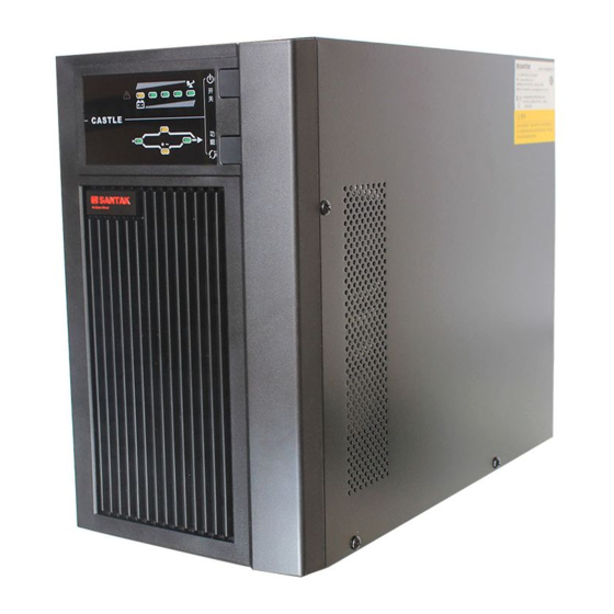
Page 5: Appearance
1. Brief introduction 1.3 Appearance RS232 Intelligent slot External battery socket Input breaker TB cover Terminal Block Cable tying BACK VIEW of C6K(e)/C6KS(e) RS232 Intelligent slot External battery socket Input breaker TB cover Terminal Block Cable tying BACK VIEW of C10K(e)/C10KS(e) -
Page 6: Product Specification And Performance
1. Brief introduction 1.4 Product specification and performance General specification C6K(e) C6KS(e) C10K(e) C10KS(e) Model 6kVA/4.2kW 6kVA/4.2kW 10kVA/7kW 10kVA/7kW Power Rating Frequency (Hz) Voltage (176-276)VAC (176-276)VAC (176-276)VAC (176-276)VAC Input Current 31A max. 31A max. 50A max. 50A max. Frequency 46Hz~54Hz 46Hz~54Hz 46Hz~54Hz 46Hz~54Hz... -
Page 7: Installation
2. Installation 2.1 Unpacking and inspection 1) Unpack the packaging and check the package contents. The ship- ping package contains: A UPS A user manual A communication cable A battery cable (for C6KS(e)/C10KS(e) ) 2) Inspect the appearance of the UPS to see if there is any damage during transportation. - Page 8 2. Installation 3) For C10K(e)/C10KS(e) UPS, it is recommended to select the UL1015 8AWG(10mm ) wire or other insulated wire which complies with AWG Standard for the UPS input and output wirings. Note: Do not use the wall receptacle as the input power source for the UPS, as its rated current is less than the UPS’...
-
Page 9: Operating Procedure For Connecting The Long Backup Time Model Ups
2. Installation Input and Output Terminal Block wiring diagram of C6K(e)/C6KS(e)C10K(e)/C10KS(e) Operating procedure for connecting the long backup time model UPS with the external battery 1. The nominal DC voltage of external battery pack is 240VDC. Each battery pack consists of 20 pieces of 12V maintenance free batter- ies in series. - Page 10 2. Installation 3. To complete the connection by plugging the connector of the external battery cable into the external battery socket of the UPS. Do not attempt to connect any loads to the UPS now. You should connect the input power wire to the right position first. And then set the breaker of the battery pack in the “...
-
Page 11: Operation And Operating Mode
3. Operation and Operating mode It is easy to operate the equipment, with no previous training. You just need to read through this manual and operate according to the instructions in it. The meaning of the LED indicators, please refer to the appendix 1 “ Display panel” . 3.1 Operation 1. -
Page 12: Operating Mode
3. Operation and Operating mode from the UPS, simply cut off the utility power supply and the UPS will perform self-diagnosis, finally not any display is shown on the display panel and no voltage output is available from the UPS output. 4. - Page 13 3. Operation and Operating mode Note: Please follow the following steps to connect the generator: Activate the generator and wait until the operation is stable before supplying power of the generator to the UPS (be sure that the UPS is in idle mode). Then turn on the UPS according to the start-up procedure.
- Page 14 3. Operation and Operating mode 3. Bypass mode The display panel in bypass mode is shown in the following dia- gram Fig.3-3. The utility power LED and the bypass LED are lit. The displayed number of the load LEDs will be turned on in accordance with the load capacity connected.
- Page 15 3. Operation and Operating mode 5. Backup time for the standard model The backup time of the long backup time model is dependent on the external battery pack capacity and the load level as well as other factors. The backup time of standard model may vary from different models and load level.
- Page 16 3. Operation and Operating mode 6. Communication Interface Intelligent slot This series is equipped with an intelligent slot for Webpower (optional accessory) or other optional card to achieve remote management of the UPS through internet / intranet. Please contact your local distribu- tor for further information.
-
Page 17: Battery Maintenance
4. Battery maintenance This series UPS only requires minimal maintenance. The battery used for standard models are valve regulated sealed lead-acid maintenance free battery. These models require minimal repairs. The only require- ment is to charge the UPS regularly in order to maximize the expected life of the battery. -
Page 18: Notes For Battery Disposal And Battery Replacement
5. Notes for battery disposal and battery replacement 1) Before disposing of batteries, remove conductive jewelry such as necklace, wrist watches and rings. 2) If it is necessary to replace any connection cables, please purchase the original materials from the authorized distributors or service centers, so as to avoid overheat or spark resulting in fire due to insufficient capacity. -
Page 19: Troubleshooting
6.Troubleshooting Solution Problem Possible cause Make sure the UPS is not overloaded; The #1 Fault LED and the the air vents are not blocked and the The UPS shutdown due #6 LED are turned on, the ambient temperature is not too high. to internal overheat buzzer beeps continuously Wait for 10 minutes for the UPS to... -
Page 20: Troubleshooting
6.Troubleshooting Problem Possible cause Solution Check the battery. If the battery is Battery low or battery not Battery LED flashes damaged,replace the battery immedi- connected ately and ensurethat the battery breaker is in “ ON” position. The utility power is normal, AC input breaker in Set the input breaker in “... -
Page 21: Appendix 1 Display Panel
Appendix 1. Display panel Indicator 1: Fault LED Power off Indicator 2: Load/Battery LED Power on / Alarm Silence Indicator 3: Load/Battery LED Indicator 4: Load/Battery LED Indicator 7: Bypass LED Indicator 5: Load/Battery LED Indicator 6: Load/Battery LED Indicator 9: INV LED Indicator 8: Utility Power LED Indicator 10: Battery LED Power ON/OFF: To turn on the UPS simply by pressing the “ON”... -
Page 22: Appendix 2 The Corresponding Form Of The Led Display
Appendix 2. The corresponding form of the LED display LED display Operating state Alarm warning 1# 2# 3# 5# 6# 7# 8# 9# 10# 0~35% none Load capacity Utility Power 36%~55% none Mode Load capacity 56%~75% none Load capacity 76%~95% none Load capacity 96%~105%... - Page 23 Appendix 2. The corresponding form of the LED display LED display Operating state Alarm warning 1# 2# 3# 5# 6# 7# 8# 9# 10# Continuously Over temperature beep Continuously Inv abnormal beep Continuously Output short circuited beep Continuously BUS voltage abnormal beep Beep once every Charger and battery failed...
-
Page 24: Appendix 3 Warranty
Appendix 3. Warranty Warranty Santak Corp. offers the buyer and the client (hereinafter referred to as 'the Buyer') the following limited warranty for repair: Starting from the initial date when the Buyer purchases the product from Santak or the distributor/the retailer of Santak, the Uninterruptible Power... - Page 25 614-06745-00...
Need help?
Do you have a question about the Castle C6K(E) and is the answer not in the manual?
Questions and answers
Error 2 and goes to bypass when machine switched on