Advertisement
Advertisement

Related Manuals for iSolution iMove 50S


Summary of Contents for iSolution iMove 50S
- Page 1 50S User Guide Professional Entertainment Technology...
-
Page 2: Table Of Contents
TABLE OF CONTENTS 1. Safety Instructions 2. Technical Specifications 3. How To Set The Unit 4. How To Control The Unit 5. Troubleshooting 6. Fixture Cleaning... -
Page 3: Safety Instructions
1. Safety Instruction Please read carefully the instruction, which includes important information about the installation, usage and maintenance. WARNING Please keep this User Guide for future use.. If you sell the unit to another user, be sure that they also receive this user manual. ... -
Page 4: Technical Specifications
2. Technical Specification iMove 50S is the combination of the latest high powered LED technology, excellent optics and great features. DMX control: 8/11 channels selectable. -
Page 5: How To Set The Unit
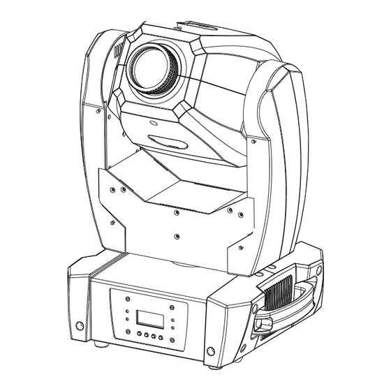
Voltage: 120V/230V, 50/60Hz Power consumption: 112W at 230V Light source: 1 x 50W LED Dimensions: 299 x 247 x 420 mm Φ wheel=109 mm gobo Φ =19 mm gobo Weight: 10 kgs Photometric diagram: 3. How To Set The Unit 3.1 Control panel... - Page 6 Display To show the various menus and the selected functions DMX input present MASTER Master Mode SLAVE Slave Mode SOUND Flashing Sound activation Button MENU To select the programming functions DOWN To go backward in the selected functions To go forward in the selected functions ENTER To confirm the selected functions Only for remote control...
- Page 8 DMX 512 Address Setting Press the MENU button to show on the display. Press the ENTER button and the display will blink. Use the DOWN and UP buttons to change the DMX512 address. Once the address has been selected, press the ENTER button to setup, to go back to the functions without any change press the MENU button again.
- Page 9 display will blink. Use the DOWN and UP buttons to select the (normal) or (2 light show) mode. Once the mode has been selected, press the ENTER button to setup, to go back to the functions without any change press the MENU button again. Hold and press the MENU button for about one second or wait for one minute to exit the menu mode.
- Page 10 Tilt Inversion Press the MENU button to show on the display. Press the ENTER button and the display will blink. Use the DOWN and UP buttons to select the (normal) or (tilt inversion) mode. Once the mode has been selected, press the ENTER button to setup, to go back to the functions without any change press the MENU button again.
- Page 11 Dimmer Calibrate Press the MENU button to show on the display. Press the ENTER button and the display will blink. Use the DOWN and UP button to calibrate the dimmer for a maximum output from (limited to 50% of the really max. output) to (maximum output is not limited).
- Page 12 Defaults Setting Press the MENU button to show on the display. Press the ENTER button and the display will blink. Use the DOWN and UP button to select the . Once the has been selected, press the ENTER button and use the UP and Down button to select the : For professional users, detailed explanation as followings: ...
-
Page 13: How To Control The Unit
Reset Press the MENU button to show on the display. Press the ENTER button and all channels of the unit will return to their standard position. To go back to the functions without any change press the MENU button again. Hold and press the MENU button for about one second or wait for one minute to exit the menu mode. - Page 14 4.1 Master/Slave Built In Preprogrammed Function By linking the units in master/slave, the first unit will control the other units to give an automatic, sound activated or synchronized light show. This function is good when you want an instant show. You have to set the first unit into master mode and select (show 1) or (show 2) or...
- Page 15 4.4 DMX 512 Configuration 8 channel modes:...
- Page 16 11 channel modes: GOBO:...
- Page 17 4.5 DMX512 Connection COMMON DMX + DMX INPUT DMX OUTPUT DMX - Termination reduces signal errors and avoids signal transmission problems and interference. It is always advisable to connect a DMX terminal. (Resistance 120 ohm 1/4W)between pin2(DMX-)and pin3(DMX+) of the last fixture. If you are using a controller with 5 pins DMX output, you need to use a 5 to 3 pin adapter-cable.
-
Page 18: Troubleshooting
3 pin XLR: Pin 1: GND, Pin 2: Negative signal (-), Pin 3: Positive signal (+) 5 pin XLR: Pin 1: GND, Pin 2: Negative signal (-), Pin 3: Positive signal (+), Pin 4/Pin 5: Not used. 5. Troubleshooting Following are a few common problems that may occur during operation. Here are some suggestions for easy troubleshooting: A. -
Page 19: Fixture Cleaning
6. Fixture Cleaning The cleaning of internal and external optical lenses and/or mirrors must be carried out periodically to optimize light output. Cleaning frequency depends on the environment in which the fixture operates: damp, smoky or particularly dirty surrounding can cause greater accumulation of dirt on the unit’s optics. - Page 20 EC Declaration of Conformity We declare that our products (lighting equipments) comply with the following specification and bears CE mark in accordance with the provision of the Electromagnetic Compatibility (EMC) Directive 89/336/EEC. EN55014-2: 1997 A1: 2001, EN61000-4-2: 1995; EN61000-4-3: 2002; EN61000-4-4: 1995;...
Need help?
Do you have a question about the iMove 50S and is the answer not in the manual?
Questions and answers