
Related Manuals for Insportline SPORTline EG-7820


Summary of Contents for Insportline SPORTline EG-7820
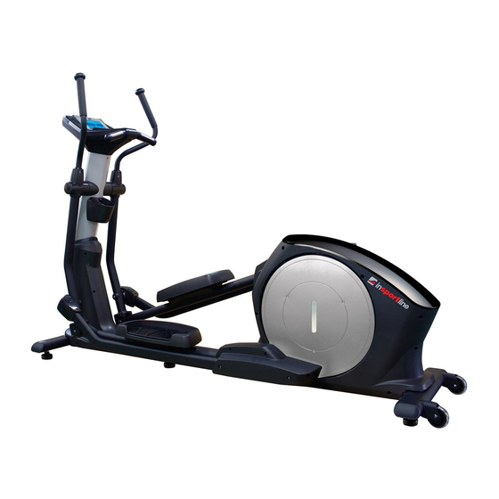
- Page 1 USER MANUAL – EN IN 9322 Elliptical Trainer SPORTline EG-7820 Product May Vary Slightly From Picture MADE IN TAIWAN...
-
Page 2: Table Of Contents
CONTENTS SAFETY INSTRUCTIONS............................3 BEFORE YOU BEGIN.............................4 HARDWARE IDENTIFICATION CHART......................5 ASSEMBLY PARTS..............................6 ASSEMBLY INSTRUCTIONS..........................7 HOW TO ADJUST CONSOLE ANGLE......................14 HOW TO TOW THE ITEM SAFELY.......................14 CONSOLE OVERVIEW............................15 CONDITIONING GUIDELINES...........................30 EXERCISE INTENSITY............................30 WARM-UP AND COOL-DOWN........................31 SUGGESTED STRETCHING EXERCISES.....................31 PARTS LIST................................33 PRODUCT PARTS DRAWING (A)........................37 PRODUCT PARTS DRAWING (B)........................38 TERMS AND CONDITIONS OF WARRANTY, WARRANTY CLAIMS............39... -
Page 3: Safety Instructions
CAUTION: Weight on this product should not exceed 181kg / 400lbs. WARNING! Exercise can present a health risk. Consult a physician before beginning any exercise program with this equipment. If you feel faint or dizzy, immediately discontinue use of this equipment. Serious bodily injury can occur if this equipment is not assembled and used correctly. -
Page 4: Before You Begin
21. Make sure that adequate space is available for access to and passage around the Elliptical Trainer; keep at least a distance of 1 meter from any obstruction object while using the machine. 22. The Elliptical Trainer is well-suited to commercial usage. WARNING: Before starting any exercise or conditioning program you should consult with your personal physician to see if you require a complete physical exam. - Page 5 T-HAND SOCKET SOCKET WRENCH WRENCH (17mm) PHILLIPS WRENCH (17mm) (13mm) SCREWDRIVER (6mm)
-
Page 6: Hardware Identification Chart
HARDWARE IDENTIFICATION CHART Unpack the box in a clear area. Use the List of Hardware below to check the contents of the hardware kit. This chart is provided to help identify the hardware used in the assembly process. Place the washers, the end of bolts, or screws on the circles to check for the correct diameter. -
Page 7: Assembly Parts
116 Bolt (M10x1.25x85mm) 126 Nylon Nut (M10xp1.5) HARDWARE KIT B Part No. and Description Q’TY 100 Bolt (M5xp0.8x15mm) 105 Bolt (M8xp1.25x10mm) 117 Bolt (M10xp1.5x50mm) ASSEMBLY PARTS Unpack the box in a clear area. Follow the List of Assembly Parts below to check and make sure all assembly parts are present and in good condition. -
Page 8: Assembly Instructions
Upright Sleeve Leveler Console Fixed Bracket Front & Rear Stabilizer Main Frame ASSEMBLY INSTRUCTIONS Place all parts from the box in a cleared area and position them on the floor in front of you. Remove all packing materials from your area and place them back into the box. Do not dispose of the packing materials until assembly is completed. - Page 9 Attach 4pcs Levelers (75) to the Front Stabilizer (2) and the Rear Stabilizer (3). Be sure to tighten the Levelers (75) securely against the Stabilizers (2, 3) until screw lines are eliminated as the drawing 1 shown above. In order to assemble the Stabilizer (2, 3) smoothly, it is suggested to place one Styrofoam (or any stationary object) under one side of the Main Frame (1).
- Page 10 Slide the Upright Sleeve (36) onto the Upright Post (4.) Refer to the insert drawing. Make sure the direction of the Upright Sleeve (36) is in the correct position. Plug the Middle Connection Wire (131) into the Lower Connection Wire (132). STEP 3: Upright Post Assembly Ensure 2pcs Nylock Nuts (M10xp1.5)(125) have preassembled into the front of the Main Frame (1) as FIG1 illustration (they will not be tight so that slotted bracket of the upright post will slide between the...
- Page 11 Attach the Front Decorative Cover (19) onto the front of the Main Frame (1) with 2pcs Bolts (M5xp0.8x50mm)(101). Paste a Logo Sticker on the surface of the Front Decorating Upright Cover (19). A logo sticker is included in one of the hardware boxes. STEP 6: Pivoting Arm Cover Assembly Attach the Left-Rear Pivoting Arm Cover (49) and Right-Rear Pivoting Arm Cover (50) and secure with 4pcs Bolts (M5xp0.8x15mm)(100).
- Page 12 STEP 7: Console Bracket and Console Fixed Bracket Assembly CAUTION: Be careful not to damage the Middle Pulse Sensor Wire (135) while assembling STEP 7. Slide the Console Bracket (43) onto the Front & Back Upright Cover (61, 62) as the FIG1 illustration shows above.
- Page 13 STEP 9: Console Battery Assembly Loosen the Screw (M3x10mm) (95) at the bottom on the console by using the combination wrench to open the Battery Door (42). The Console (41) operates with FOUR AA rechargeable batteries, four batteries are included in the hardware box.
- Page 14 STEP 11: Console and Console Bracket Assembly Place the Console (41) onto the Upright Post (4) and secure with the Screw, Round Head (M5xp0.8x15mm) (100). Attach the Console Lower Case (39) to the Console (41) under the Stationary Handlebar (5) and secure with the Screw, Round Head (M5xp0.8x15mm) (100).
-
Page 15: How To Adjust Console Angle
Fasten the Covers together with the 4pcs Bolts (M5xp0.8x15mm)(100). Repeat the above same procedure on the left side. STEP 15: Pedal Assembly Attach the Left Pedal (59) onto the iron plate that is located in the middle of the Left Pedal Arm (12) and secure with 4pcs Bolts (M8xp1.25x10mm)(105). -
Page 16: Console Overview
CONSOLE OVERVIEW The console display may vary slightly from the actual console display, the above console overview is for reference only The console has metric and imperial system difference due to the usage of the different countries - Distance: 0.0~99.9 Km/Mile... -
Page 17: Power Off
POWER ON a) Pedaling to activate the console. b) The activated LCD console lights up along with a long beep sound. LCD diagram appears as below: Enter into the initial setting mode after around two seconds as below: Initial setting mode POWER OFF The console would automatically shut off after 30 seconds of inactivity. - Page 18 FUNCTION BUTTONS PROGRAM/MODE: Press the button to select the desired mode – “MANUAL”, “PROGRAM”, “USER”, “TARGET H.R.” as shown: Press the “ENTER” to confirm and enter the function value setting. ENTER: The button is equipped with TWO operating methods. Press the button to confirm and enter the selected mode (“MANUAL”, “PROGRAM”, “USER”, “TARGET H.R.”).
-
Page 19: Manual Mode
The RESET function only operates under PAUSE MODE MANUAL MODE There are four ways to enter into MANUAL MODE as below: POWER OFF STATUS (LCD diagram disappear on LCD window): Pedaling to activate the console. The activated LCD console lights up along with a long beep sound. LCD diagram appears as shown below: Enter into the initial setting mode after around two seconds as shown below: RESTART FUNCTION:... - Page 20 The RESET function only operates under PAUSE MODE Skip to Step B. of NORMAL OPERATION on the next page to continue the operation. QUICK START: START/PAUSE” button: Press the “START/PAUSE” button directly to start a workout under “MANUAL MODE” without any setting. Skip to Step C.
- Page 21 TIME (01:00 to 99:00; 1minute increment) DISTANCE (0.1 to 99.9km; 0.1km increment) CALORIES (10 to 990 Kcal; 10 Kcal Increment) PULSE (70 to 240 BPM; 1BPM increment) Press the “ENTER” button to confirm the function value and enter the next function value setting.
-
Page 22: Program Mode
will turn to zero when detecting your pulse. after turning 2. WARNING BEEP SOUND off) EMIT CONSTANTLY FROM A CONSOLE: If your pulse is greater than the SELECTED PULSE VALUE during workout, the short warning beep sound will constantly emit. Please note that this is a warning for you to slow down or decrease the workload level. - Page 23 Press the “START/PAUSE” button to pause the current program. Hold the “RESET” button for FOUR SECONDS to enter into the initial setting mode as illustration shown below. The RESET function only operates under PAUSE MODE Skip to Step B. of NORMAL OPERATION on the next page to continue the operation. NORMAL OPERATION: “START/PAUSE”...
- Page 24 After pressing the “ENTER” button, the flashing “TIME” will appear on the LCD window. “UP” or “DOWN” button: Press the “UP” or “DOWN” button to select the program time as desire. NOTE: The console will cycle through the functions as follow and allow users to set the function values.
- Page 25 To reset the function value to zero, press the “RESET” button. START/PAUSE” button: To start a workout, press the “START/PAUSE” button. WITHOUT PULSE VALUE: “ ” flashing symbol will appear when detecting your pulse. THE WARNING BEEP SOUND EMIT CONSTANLY DURING WORKOUT: If your pulse is greater than the SELECTED PULSE VALUE during workout, the short warning beep sound will constantly emit.
- Page 26 “ENTER” button: Press the “ENTER” button for confirming and entering the function value setting. “UP” or “DOWN” button: Press the “UP” or “DOWN” button to choose P12 as the following illustration shown. “ENTER” button: Press the “ENTER” button to enter Program 12. “UP”...
- Page 27 Enter into the initial setting mode after around two seconds as shown below: RESTART FUNCTION: Press the “START/PAUSE” button to pause the current program. Hold the “RESET” button for FOUR SECONDS to enter into the initial setting mode as illustration shown below.
- Page 28 “ENTER” button: Press the “ENTER” button for confirming and entering the function value setting. “PAUSE MODE” single will appear on LCD window for setting. “START/PAUSE” button: After flashing “the first time interval of the workload level” appears on LCD window, press the “START/PAUSE” button to start a workout directly without setting function values (“TIME INTERVAL 1”...
- Page 29 To reset the function value to zero, press the “RESET” button. To start a workout, press the “START/PAUSE” button. Under PAUSE or START mode, the user could press the “UP” or “DOWN” button to adjust workload level. WITHOUT PULSE VALUE: “...
- Page 30 The RESET function only operates under PAUSE MODE Skip to Step B. of NORMAL OPERATION on the next page to continue the operation. NORMAL OPERATION: “START/PAUSE” button: Press the “START/ PAUSE” button to pause the current program. “PROGRAM” button: Press the “PROGRAM” button to select “TARGET H. R.” as shown. “ENTER”...
-
Page 31: Conditioning Guidelines
“UP” or “DOWN” button: Press the “UP” or “DOWN” button to the select the function value of “TIME” as desire. NOTE: The console will cycle through the functions as follow and allow users to set the function values. TIME (01:00 to 99:00; 1minute increment) DISTANCE (0.1 to 99.9km; 0.1km increment) CALORIES (10 to 990 Kcal;... -
Page 32: Warm-Up And Cool-Down
During the first few months of your exercise program, keep your heart rate near the low end of your target zone as you exercise. After a few months, your heart rate can be increased gradually until it is near the middle of your target zone as you exercise. - Page 33 Bent Torso Pulls While sitting on the floor, have legs apart one leg straight and one knee bent. Pull the chest down to touch the thigh on the leg that is bent and twist at the waist. Hold this position at least 10 seconds. Repeat 10 times on each side.
-
Page 34: Parts List
PARTS LIST Item Name Q'ty Main Frame Front Stabilizer Rear Stabilizer Upright Post Stationary Handlebar Left Upper Handlebar Right Upper Handlebar Left Pivoting Arm Right Pivoting Arm Left Pedal Support Arm Right Pedal Support Arm Left Pedal Arm Right Pedal Arm Pedal Suspension Tube Pedal Arm Connector Front Left-Side Cover... - Page 35 Accessory Tray Inner Rotator Cuff-Pivoting Arm Console Lower Case Console Battery Door Console Bracket Foam Grip Assembly Handheld Plug Front Rotator Cuff-Pivoting Arm Back Rotator Cuff-Pivoting Arm Middle Rotator Cuff Left-Rear Pivoting Arm Cover Right-Rear Pivoting Arm Cover Left-Middle Pivoting Arm Cover Right-Middle Pivoting Arm Cover Left-Rear Pedal Cover (outer) Left-Rear Pedal Cover (inner)
- Page 36 Pedal Suspension Stand Shaft Spacer Shaft Cap Suspension Tube Spacer Bearing (6004) Bearing (6905) Square Key (6×6×16mm) C Ring Tension Bracket Eye Bolt Lock Washer (M6) Lock Washer (M8) Washer (8×23×2.0t) Washer (8×26×2.0t) Washer (8×30×2.0t) Washer (8×38×2.0t) Washer (10×23×2.0t) Washer (21×30×1.0t) Screw (M3×10mm) Screw (M4×20mm) Screw (M5×18mm)
- Page 37 Bolt (M10×p1.5×70mm) Bolt (M10×p1.5×85mm) Bolt (M10×p1.5×50mm) Bolt (M8×p1.25×75mm) Bolt (M6×p1.0×12mm) Bolt (L=35mm) Nut (M8×p1.25) Nylon Nut (M6×p1.0) Nylon Nut (M8×p1.25) Nylon Nut (M8×p1.25) Nylon Nut (M10×p1.5) Nylon Nut (M10×p1.5) Flange Nut (M10×p1.25) Nut (M10×p1.25) Generator Connection Wire Upper Connection Wire Middle Connection Wire Lower Connection Wire Sensor Wire &...
-
Page 38: Product Parts Drawing (A)
PRODUCT PARTS DRAWING (A) -
Page 39: Product Parts Drawing (B)
PRODUCT PARTS DRAWING (B) -
Page 40: Terms And Conditions Of Warranty, Warranty Claims
TERMS AND CONDITIONS OF WARRANTY, WARRANTY CLAIMS General Conditions of Warranty and Definition of Terms All Warranty Conditions stated hereunder determine Warranty Coverage and Warranty Claim Procedure. Conditions of Warranty and Warranty Claims are governed by Act No. 40/1964 Coll. Civil Code, Act No. 513/1991 Coll., Commercial Code, and Act No. - Page 41 +420 556 770 190, Mobile: +420 604 853 019, servis@insportline.cz Fax: +420 556 770 192, (Service +420 556 770 191) Web: www.insportline.cz, www.worker.cz, www.worker-moto.cz INSPORTLINE, s.r.o. Bratislavska 36, 911 05 Trencin, Slovakia CRN: 36311723, VAT ID: SK2020177082 Orders: +421(0)326 526 701, +421(0)917 649 192, objednavky@insportline.sk...
Need help?
Do you have a question about the SPORTline EG-7820 and is the answer not in the manual?
Questions and answers