
Related Manuals for Kramer VP-4x4


Summary of Contents for Kramer VP-4x4
- Page 1 Kramer Electronics, Ltd. USER MANUAL Model: VP-4x4 4x4 VGA/XGA Audio Matrix Switcher...
-
Page 2: Table Of Contents
Getting Started Quick Start Overview Your VGA/XGA Audio Matrix Switcher Installing the VP-4x4 on a Rack Connecting the VP-4x4 4x4 VGA XGA Audio Matrix Switcher Connecting the VP-4x4 Rear Panel Connecting the Balanced/Unbalanced Stereo Audio Input/Output Connecting a PC Cascading Machines 6.4.1... - Page 3 Table 3: Dipswitch Settings Table 4: Machine # Dipswitch Settings Table 5: Technical Specifications of the VP-4x4 VGA/XGA Audio Matrix Switcher Table 6: VP-4x4 Hex Codes for Switching via RS-232/RS-485 Table 7: VP-4x4 Hex Codes for Switching Audio Channels via RS-232/RS-485...
-
Page 4: Introduction
3 We recommend that you use only the power cord that is supplied with this machine 4 Download up-to-date Kramer user manuals from our Web site at http://www.kramerelectronics.com 5 The complete list of Kramer cables is on our Web site at http://www.kramerelectronics.com... - Page 5 Getting Started VGA/XGA Machine # 1 (= Master) Source VGA/XGA Source Machine # 2 VGA/XGA Source Up to 8 Display Units Display Display VGA/XGA Source Display KRAMER: SIMPLE CREATIVE TECHNOLOGY...
-
Page 6: Overview
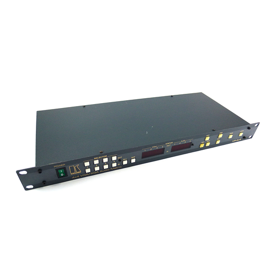
Kramer VP-4x4 away from moisture, excessive sunlight and dust Your VGA/XGA Audio Matrix Switcher Figure 1 illustrates the front and rear panels of the VP-4x4. Table 1 and Table 2 define the front and rear panels of the VP-4x4, respectively. -
Page 7: Figure 1: Vp-4X4 Vga/Xga Audio Matrix Switcher
Your VGA/XGA Audio Matrix Switcher Figure 1: VP-4x4 VGA/XGA Audio Matrix Switcher KRAMER: SIMPLE CREATIVE TECHNOLOGY... -
Page 8: Table 1: Front Panel Vp-4X4 Vga/Xga Audio Matrix Switcher Features
Your VGA/XGA Audio Matrix Switcher Table 1: Front Panel VP-4x4 VGA/XGA Audio Matrix Switcher Features Feature Function Power Switch Illuminated switch for turning the unit ON or OFF SELECTOR IN Buttons Select the input to switch to the output1 SELECTOR OUT... -
Page 9: Table 2: Rear Panel Vp-4X4 Vga/Xga Audio Matrix Switcher Features
Your VGA/XGA Audio Matrix Switcher Table 2: Rear Panel VP-4x4 VGA/XGA Audio Matrix Switcher Features Feature Function AUDIO INPUTS Terminal Connect to the balanced stereo audio sources (from 1 to 4) Block Connectors INPUT HD15F Connectors Connects to the VGA/XGA video sources (from 1 to 4) -
Page 10: Installing The Vp-4X4 On A Rack
Installing the VP-4x4 on a Rack Installing the VP-4x4 on a Rack This section describes what to do before installing on a rack and how to rack mount. Before Installing on a Rack How to Rack Mount Before installing on a rack, be sure that the environment is... -
Page 11: Connecting The Vp-4X4 4X4 Vga Xga Audio Matrix Switcher
1 You do not need to connect all inputs and outputs 2 Switch OFF the power on each device before connecting it to your VP-4x4. After connecting your VP-4x4, switch on its power and then switch on the power on each device 3 See section 6.2... -
Page 12: Figure 2: Connecting The Vp-4X4 Vga/Xga Audio Matrix Switcher
Connecting the VP-4x4 4x4 VGA XGA Audio Matrix Switcher VGA/XGA Source VGA/XGA Source VGA/XGA Source Display Display Display VGA/XGA Source Display Figure 2: Connecting the VP-4x4 VGA/XGA Audio Matrix Switcher... -
Page 13: Connecting The Balanced/Unbalanced Stereo Audio Input/Output
A balanced input/output connection (see Figure 3) An unbalanced audio output (see Figure 4) An unbalanced source to the balanced input on the VP-4x4 (see Figure 5) Figure 3 illustrates how to wire a balanced input/output connection (for example, audio INPUT 1 or AUDIO OUTPUT 1):... -
Page 14: Connecting A Pc
Figure 7, do the following: 1. Connect the sources and acceptors (see section 6.1). 2. Connect the RS-232 port of the first VP-4x4 unit to a PC using the Null- modem adapter provided with the machine (see section 6.3). -
Page 15: Figure 7: Control Configuration Via Rs-232 And Rs-485
Connecting the VP-4x4 4x4 VGA XGA Audio Matrix Switcher RS-485 PINOUT RS-485 Machine # 1 (= Master) Machine # 2 Up to 8 Units Machine # 8 Figure 7: Control Configuration via RS-232 and RS-485 KRAMER: SIMPLE CREATIVE TECHNOLOGY... -
Page 16: Dipswitch Settings
Connecting the VP-4x4 4x4 VGA XGA Audio Matrix Switcher 6.4.1 Dipswitch Settings The VP-4x4 includes a set of four dipswitches, as Figure 8 and Table 3 define: Figure 8: VP-4x4 Dipswitches Table 3: Dipswitch Settings DIPS Function Description 1, 2, 3... -
Page 17: Operating Your Audio Matrix Switcher
Operating Your Audio Matrix Switcher Operating Your Audio Matrix Switcher You can operate your VP-4x4 via: The front panel buttons RS-232 serial commands transmitted by a touch screen system, PC, or other serial controller 7.1 Displaying Unit Characteristics Figure 9 shows an example of the display immediately after switching on the power, or after resetting the machine (by pressing SELECTOR IN buttons 1, 2 and 3 simultaneously for three seconds). -
Page 18: Setting The Audio-Follow-Video Option
Operating Your Audio Matrix Switcher 7.2.1 Setting the Audio-Follow-Video Option To set the Audio-Follow-Video (AFV) option: 1. Press the AFV button. The AFV button illuminates. The audio will follow the video. 2. If the audio configuration differs from the video configuration, both the Audio IN STATUS 7-segment displays and the AUD button will blink , and require reconfiguring for AFV operation. -
Page 19: Confirming Settings
You can key-in several actions and then confirm them by pressing the TAKE button once, to simultaneously switch all monitors Pressing an OUT-IN combination when your VP-4x4 operates in the AT ONCE mode implements the switch immediately. When the VP-4x4 operates in the CONFIRM mode, press the blinking TAKE button to authorize the switch. -
Page 20: Confirming A Switching Action
Operating Your Audio Matrix Switcher 7.4.2 Confirming a Switching Action To confirm a switching action (in CONFIRM mode), do the following: 1. Press an OUT-IN combination. The corresponding AUDIO and VIDEO IN STATUS 7-segment displays blink. The TAKE button also blinks. 2. -
Page 21: Recalling An Input/Output Configuration
The memory recalls the stored data from that reference. If you cannot remember which of the eight input/output configurations is the one that you want, set the VP-4x4 to the CONFIRM mode and manually scan all the input/output configurations until you locate it. -
Page 22: Technical Specifications
Technical Specifications Technical Specifications Table 5 includes the technical specifications: Table 5: Technical Specifications of the VP-4x4 VGA/XGA Audio Matrix Switcher INPUTS: 4 analog red, green, blue signals - 0.7 Vpp/75 , H & V syncs, TTL level on HD15F connectors 4 balanced audio stereo signals, + 4dBm/33K typical, 21 Vpp max. -
Page 23: Table Of Hex Codes For Serial Communication
IN 3 IN 4 Table 7 lists the Hex values for switching audio channels via RS-232/RS-485: Table 7: VP-4x4 Hex Codes for Switching Audio Channels via RS-232/RS-485 Switching Audio Channels OUT 1 OUT 2 OUT 3 OUT 4 IN 1... -
Page 24: Kramer Protocol 2000
Kramer Protocol 2000 10 Kramer Protocol 2000 The VP-4x4 is compatible with Kramer’s Protocol 2000 (version 0.46) (below). This RS-232/RS-485 communication protocol uses four bytes of information as defined below. For RS-232, a null-modem connection between the machine and controller is used. The default data rate is 9600 baud, with no parity, 8 data bits and 1 stop bit. -
Page 25: Table 9: Instruction Codes For Protocol 2000
2 - for VGA SET HIGHEST 0 - for video Set equal to highest machine MACHINE ADDRESS 1 - for audio address REQUEST HIGHEST 0 - for video MACHINE ADDRESS 1 - for audio KRAMER: SIMPLE CREATIVE TECHNOLOGY... - Page 26 Kramer Protocol 2000 INSTRUCTION DEFINITION FOR SPECIFIC INSTRUCTION NOTE DESCRIPTION INPUT OUTPUT REQUEST WHETHER SETUP # 0 - for checking if setup is defined SETUP IS DEFINED / 1 - for checking if input is valid VALID INPUT IS Input #...
- Page 27 OUTPUT is assigned the value of the requested parameter. The replies to instructions 10 and 11 are as per the definitions in instructions 7 and 8 respectively. For example, if the present status of machine number 5 is breakaway setting, then the reply to the HEX code would be HEX codes KRAMER: SIMPLE CREATIVE TECHNOLOGY...
- Page 28 Kramer Protocol 2000 NOTE 5 – For the OUTPUT byte set as 6, the VIS source is the input selected using the OUTPUT byte. Similarly, for the OUTPUT byte set as 7, the VIS source is the output selected using the OUTPUT byte. Note also, that on some machines the sync source is not software selectable, but is selected using switches, jumpers, etc! NOTE 6 –...
- Page 29 (in real-time). For example, if input 3 is detected as invalid, the unit will send the HEX codes If input 7 is detected as valid, then the unit will send HEX codes KRAMER: SIMPLE CREATIVE TECHNOLOGY...
- Page 30 EXCLUSION OF DAMAGES The liability of Kramer for any effective products is limited to the repair or replacement of the product at our option. Kramer shall not be liable for: Damage to other property caused by defects in this product, damages based upon inconvenience, loss of use of the product, loss of time, commercial loss;...
- Page 31 For the latest information on our products and a list of Kramer distributors, visit our Web site: www.kramerelectronics.com, where updates to this user manual may be found. We welcome your questions, comments and feedback. Safety Warning: Disconnect the unit from the power supply before opening/servicing.
Need help?
Do you have a question about the VP-4x4 and is the answer not in the manual?
Questions and answers