Table of Contents
Advertisement
Quick Links
Advertisement
Table of Contents

Related Manuals for Kramer VP-12x8


Summary of Contents for Kramer VP-12x8
- Page 1 Kramer Electronics, Ltd. USER MANUAL Model: VP-12x8 12x8 UXGA Matrix Switcher...
-
Page 2: Table Of Contents
Introduction Getting Started Quick Start Overview Terminology Used in this User Manual Your VP-12x8 12x8 UXGA Matrix Switcher Installing the VP-12x8 on a Rack Connecting the VP-12x8 Connecting the VP-12x8 Rear Panel Controlling via RS-232 (for example, using a PC) Control Configuration via the Ethernet Port 6.3.1... - Page 3 Contents Figures Figure 1: VP-12x8 12x8 UXGA Matrix Switcher – Front and Rear View Figure 2: VP-12x8 12x8 UXGA Matrix Switcher – Underside View Figure 3: Connecting the VP-12x8 12x8 VGA / UXGA Matrix Switcher Figure 4: Connecting a PC without using a Null-modem Adapter...
-
Page 4: Introduction
Rack Adapters; GROUP 11: Sierra Products 2 Downloadable from our Web site at http://www.kramerelectronics.com 3 Download up-to-date Kramer user manuals from our Web site at http://www.kramerelectronics.com 4 The complete list of Kramer cables is on our Web site at http://www.kramerelectronics.com... - Page 5 Getting Started KRAMER: SIMPLE CREATIVE TECHNOLOGY...
-
Page 6: Overview
The Kramer VP-12x8 is a high performance matrix switcher for computer graphics video signals, with resolutions ranging from VGA through UXGA and higher on 15-pin HD connectors. The VP-12x8 can route any or all the inputs to any or all the outputs simultaneously. -
Page 7: Terminology Used In This User Manual
Protocol/Internet protocol in an intranet or an extranet. Protocol (TCP/IP) Your VP-12x8 12x8 UXGA Matrix Switcher Figure 1, Table 2 and Table 3 define the VP-12x8 12x8 UXGA Matrix Switcher. KRAMER: SIMPLE CREATIVE TECHNOLOGY... -
Page 8: Figure 1: Vp-12X8 12X8 Uxga Matrix Switcher - Front And Rear View
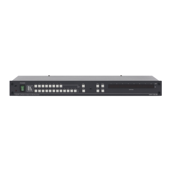
Your VP-12x8 12x8 UXGA Matrix Switcher Figure 1: VP-12x8 12x8 UXGA Matrix Switcher – Front and Rear View... -
Page 9: Table 2: Front Panel Vp-12X8 12X8 Uxga Matrix Switcher Features
Your VP-12x8 12x8 UXGA Matrix Switcher Table 2: Front Panel VP-12x8 12x8 UXGA Matrix Switcher Features Feature Function IR Receiver The red LED is illuminated when receiving signals from the Infra-red remote control transmitter POWER Switch Illuminated switch for turning the unit ON or OFF... -
Page 10: Figure 2: Vp-12X8 12X8 Uxga Matrix Switcher - Underside View
Your VP-12x8 12x8 UXGA Matrix Switcher Figure 2 illustrates the underside of the VP-12x8 unit, and Table 4 defines the underside features. Figure 2: VP-12x8 12x8 UXGA Matrix Switcher – Underside View Table 4: VP-12x8 Underside Panel Features Feature Function... -
Page 11: Installing The Vp-12X8 On A Rack
Installing the VP-12x8 on a Rack Installing the VP-12x8 on a Rack This section describes what to do before installing in a rack and how to rack mount. Before Installing in a Rack How to Rack Mount Before installing in a rack, be sure that the environment is... -
Page 12: Connecting The Vp-12X8
ETHERNET PROGRAM switches. These are only used for upgrading to the latest Kramer firmware (see section 8) 2 When less than eight outputs are required, connect only those outputs of the VP-12x8 that are required, and leave the other outputs unconnected... -
Page 13: Figure 3: Connecting The Vp-12X8 12X8 Vga / Uxga Matrix Switcher
Connecting the VP-12x8 RS-232 Computer Graphics Source 1 Display 1 Computer Graphics Source 12 Display 8 Figure 3: Connecting the VP-12x8 12x8 VGA / UXGA Matrix Switcher KRAMER: SIMPLE CREATIVE TECHNOLOGY... -
Page 14: Controlling Via Rs-232 (For Example, Using A Pc)
To connect a PC to the VP-12x8 unit, using the Null-modem adapter provided with the machine (recommended): Connect the RS-232 9-pin D-sub rear panel port on the VP-12x8 unit to the Null-modem adapter and connect the Null-modem adapter with a... -
Page 15: Control Configuration Via The Ethernet Port
Connecting the VP-12x8 6.3 Control Configuration via the Ethernet Port You can connect the VP-12x8 via the ETHERNET in the following ways: For direct connection to the PC, use a crossover cable (see section 6.3.1) For connection via a network hub or network router, use a straight-through cable (see section 6.3.2) -
Page 16: Connecting The Ethernet Port Via A Network Hub (Straight-Through Cable)
6.3.2 Connecting the ETHERNET Port via a Network Hub (Straight- Through Cable) You can connect the Ethernet port of the VP-12x8 to the Ethernet port on a network hub or network router, via a straight-through cable with RJ-45 connectors. 6.3.3... -
Page 17: Operating The Vp-12X8
Operating the VP-12x8 Operating the VP-12x8 This section describes: The 7-segment display (see section 7.1) How to confirm settings (see section 7.2) How to store and recall IN/OUT combinations (see section 7.3) How to lock the front panel buttons (see section 7.4) 7.1 Displaying Unit Characteristics... -
Page 18: Toggling Between The At Once And Confirm Modes
Operating the VP-12x8 In the Confirm mode (TAKE button is illuminated): You can key-in several actions and then confirm them by pressing the TAKE button, to simultaneously activate the multiple switches Every action requires user confirmation, protecting against erroneous switching... -
Page 19: Storing/Recalling In/Out Configurations
The memory recalls the stored data from that reference. Tip: If you cannot remember which of the 12 input/output configurations is the one that you want, set the VP-12x8 to the Confirm mode and manually scan all the input/output configurations until you locate it. -
Page 20: Deleting An Input/Output Configuration
1 Storing a new configuration over a previous configuration (without deleting it first) replaces the previous configuration 2 Nevertheless, even though the front panel is locked you can still operate via RS-232 or RS-485, as well as via the Kramer... -
Page 21: Flash Memory Upgrade
3. Create a shortcut on your desktop to the file: “FLIP.EXE”. 8.1.2 Connecting the PC to the RS-232 Port Before installing the latest Kramer firmware version on a VP-12x8 unit, do the following: 1. Connect the RS-232 9-pin D-sub rear panel port according to section 6.2. -
Page 22: Upgrading Firmware
Flash Memory Upgrade 8.1.3 Upgrading Firmware Follow these steps to upgrade the firmware: 1. Double click the desktop icon: “Shortcut to FLIP.EXE”. The Splash screen appears as follows: Figure 8: Splash Screen 2. After a few seconds, the Splash screen is replaced by the “Atmel – Flip” window: Figure 9: Atmel –... -
Page 23: Figure 10: Device Selection Window
Figure 10: Device Selection Window 4. Click the button next to the name of the device and select from the list: AT89C51RD2: AT89C51RD2 T89C51RD2 Figure 11: Device Selection window 5. Click OK and select “Load Hex” from the File menu. KRAMER: SIMPLE CREATIVE TECHNOLOGY... -
Page 24: Figure 12: Loading The Hex
Figure 12: Loading the Hex 6. The Open File window opens. Select the correct HEX file that contains the updated version of the firmware for VP-12x8 (for example 44M_V1p2.hex) and click Open. 7. Press the keyboard shortcut key F3 (or select the “Communication / RS232”... -
Page 25: Figure 14: Atmel - Flip Window (Connected)
Memory Verify Pass appears VP12x8.hex Figure 15: Atmel – Flip Window (Operation Completed) 1 See also the blue progress indicator on the status bar 2 If an error message: “ Not Finished” shows, click Run again KRAMER: SIMPLE CREATIVE TECHNOLOGY... -
Page 26: Ethernet Flash Memory Upgrade
Before installing the latest Kramer Ethernet firmware version on the VP-12x8, do the following: 1. Connect the RS-232 DB9 port (COM 1) on the VP-12x8 to a Null- modem adapter and connect the Null-modem adapter with a 9-wire flat cable to the RS-232 DB9 COM port on your PC. -
Page 27: Upgrading Firmware
6. Disconnect the power on the VP-12x8. 7. Set the ETHERNET PROGRAM/NORMAL switch, located on the machine underside, to NORMAL. 8. Connect the power on your machine. 1 To which the VP-12x8 is connected on your PC KRAMER: SIMPLE CREATIVE TECHNOLOGY... -
Page 28: Technical Specifications
Technical Specifications Technical Specifications Table 6 includes the technical specifications: Table 6: Technical Specifications of the VP-12x8 12x8 UXGA Matrix Switcher INPUTS: 12 XGA on 15-pin HD connectors (VGA through UXGA) OUTPUTS: 8 VGA on 15-pin HD connectors (VGA through UXGA) MAX. -
Page 29: Table Of Hex Codes For Serial Communication
Table of Hex Codes for Serial Communication 10 Table of Hex Codes for Serial Communication Table 7 lists the Hex values for a single machine (MACHINE # 1): Table 7: VP-12x8 Hex Codes for Switching via RS-232/RS-485 Switching Video Channels OUT 1... -
Page 30: Kramer Protocol 2000
Kramer Protocol 2000 11 Kramer Protocol 2000 The VP-12x8 is compatible with Kramer’s Protocol 2000 (version 0.49) (below). This RS-232/RS-485 communication protocol uses four bytes of information as defined below. For RS-232, a null-modem connection between the machine and controller is used. The default data rate is 9600 baud, with no parity, 8 data bits and 1 stop bit. -
Page 31: Table 9: Instruction Codes For Protocol 2000
This code is also returned to the PC if an RS-232 instruction is sent while the machine is being programmed via the front panel. Reception of this code by the switcher is not valid. KRAMER: SIMPLE CREATIVE TECHNOLOGY... - Page 32 Kramer Protocol 2000 NOTE 12 - Under normal conditions, the machine' s present status is saved each time a change is made. The "power-down" save (auto-save) may be disabled using this code. Note that whenever the machine is turned on, the auto-save function is set.
- Page 33 EXCLUSION OF DAMAGES The liability of Kramer for any effective products is limited to the repair or replacement of the product at our option. Kramer shall not be liable for: 1. Damage to other property caused by defects in this product, damages based upon inconvenience, loss of use of the product, loss of time, commercial loss;...
- Page 34 For the latest information on our products and a list of Kramer distributors, visit our Web site: www.kramerelectronics.com, where updates to this user manual may be found. We welcome your questions, comments and feedback. Safety Warning: Disconnect the unit from the power supply before opening/servicing.
Need help?
Do you have a question about the VP-12x8 and is the answer not in the manual?
Questions and answers