Advertisement
Quick Links
Advertisement

Related Manuals for Microh LED PHANTOM ZM400


Summary of Contents for Microh LED PHANTOM ZM400
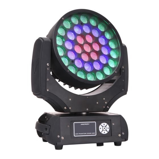
- Page 1 LED PHANTOM ZM400 www.microhpro.com OWNERS MANUAL...
-
Page 2: General Instructions
Unpacking: Thank you for purchasing the LEDPHANTOMZM400. Every LED PHANTOM ZM400 has been thoroughly tested and has been shipped in perfect operating condition. Carefully check the shipping carton for damage that may have occurred during shipping. If the carton appears to be damaged, carefully inspect your fixture for any damage and be sure all accessories necessary to operate the unit has arrived intact. - Page 3 This unit is intended for indoor use only; use of this product outdoors voids all warranties. During long periods of non-use, disconnect the unit’s main power. Always mount this unit in safe and stable matter. Power-supply cords should be routed so that they are not likely to be walked on or pinched by items placed upon or against them, paying particular attention to the point they exit from the unit.
- Page 4 Connection DMX data in/out: Locking 3-pin and 5-pin XLR AC power input: 1.5m power cord with plug Rigging Mounting points: 2 pairs of 1/4-turn locks Mounting horizontally or vertically via 2 Omega brackets Temperatures Maximum ambie nt temperature: 45 Maximum housing temperature: 75 Minimum distances Min.
- Page 5 DMX-output DMX-input XLR mounting-sockets (rear view): XLR mounting-plugs (rear view): DMX Linking: To ensure proper DMX data transmission, when using several DMX fixtures try to use the shortest cable path possible. The order in which fixtures are connected in a DMX line does not influence the DMX addressing.
-
Page 6: Led Zone Order
LED zone order Chart Size Touch Buttons: There are five buttons under the LCD display below: Normally, the LCD will display the current D MX address code of the fixture, as like, When the first line reads: “Select Menu<>”, press Menu to enter the main menu; press Up/Down to scroll in the menu or submenu o ptions;... - Page 7 LCD display operation: When in Master/Slave Synchronization Mode, only one unit in a series chain can be set as the master.
-
Page 8: Dmx Channel Mode
: ( 3 kind of channel mode optional) DMX CHANNEL MODE 14 channel mode: Channels Value Functio n On/ off 0-255 ON/OFF No function Strobe 2-255 strobe 0-255 X fine 0-255 X fine 0-255 Y fine 0-255 Y fine No function Built-in 4-31 Auto run... - Page 9 effect 3 Strobe 0-255 effect 4 Zoom 0-255 Zoom 0-255 0-255 0-255 0-255 30 channels mode: Channels Value Functio n On/ off 0-255 ON/OFF Strobe No function 2-255 strobe 0-255 X fine 0-255 X fine 0-255 Y fine 0-255 Y fine No function Built-in 4-31...
- Page 10 0-255 The 3 Circle: Red dot matrix circle dot 0-255 The 3 Circle: Green dot matrix matrix 0-255 The 3 Circle: Blue dot matrix 0-255 The 3 Circle: White dot matrix Rigging the fixture Caution: Fixture may cause severe injuries when crashing down! If you have doubts concerning the safety of a possible installation, do not install the moving head! Before rigging make sure that the installation area can hold a minimum point load of 10 times the fixture’s weight.
- Page 11 TROUBLE SHOOTING: Listed below are a few common problems the user may encounter, with solutions. Replacing fuse Only replace the fuse by a fuse of the same type and rating. Before replacing the fuse, unplug mains lead! If you need to replace the main fuse, follow the instructions: 1) Remove the rear cover of the base by unscrewing 6 fastening screws.
Need help?
Do you have a question about the LED PHANTOM ZM400 and is the answer not in the manual?
Questions and answers