
Subscribe to Our Youtube Channel
Related Manuals for Xtreme Power Conversion P90L-ISO6MB


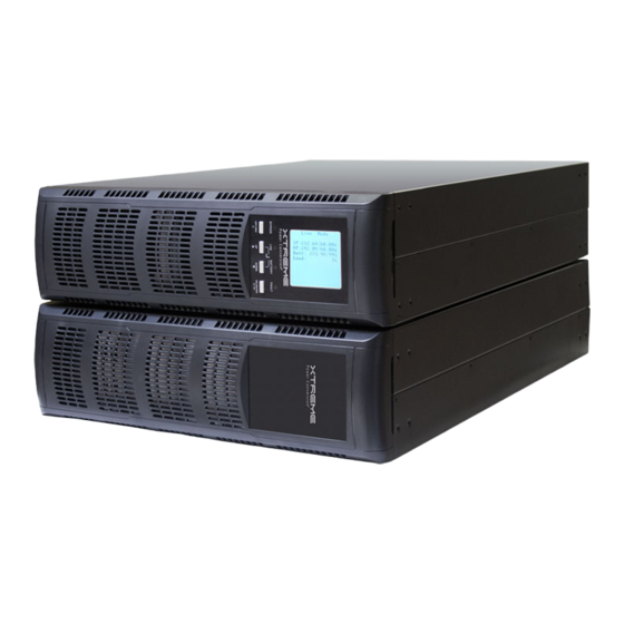
Summary of Contents for Xtreme Power Conversion P90L-ISO6MB
- Page 1 P90L 6kVA & 10kVA Online UPS 6kVA, 10kVA Models User & Installation Manual www.xpcc.com | © 2014 Xtreme Power Conversion Corporation. All rights reserved. (Rev 10/09/14)
- Page 2 Please comply with all warnings and operating instructions in this manual. Save this manual and read the following instructions carefully before install- ing the unit. Do not operate this unit before reading all safety information and operating instructions carefully. Xtreme Power Conversion Corporation Page 2...
-
Page 3: Table Of Contents
Operating Mode/Status Description....................13 Button Operation...........................13 LED Indicators..........................14 Audible Alarm..........................14 UPS Operation..........................14 LCD Operation..........................17 Main Interface (Home Screen).......................18 Operation Menu..........................18 Control Items..........................19 Measurement Pages........................21 Information Pages..........................21 Setting Menu..........................22 Alarm Page............................25 Troubleshooting..................26 Warning Status..........................26 Fault Mode............................26 Xtreme Power Conversion Corporation Page 3... - Page 4 Important Safety Warnings......................36 Installation and Setup........................36 Storage & Maintenance.........................38 Appendix B: P90L-RAIL Installation Guide...........39 Package Contents...........................39 Assembly Steps..........................39 Appendix C: P90L-ISO6MB & P90L-ISO10MB User Guide......42 Important Safety Instructions......................42 Rear Panel Explanation........................43 Installation And Operation......................44 Terminal Block Explanations for Input, Output................47 Troubleshooting..........................49 Specifications..........................49...
-
Page 5: Safety Warnings And Emc Instructions
Battery Warnings • Do not operate your UPS without connecting it to an external battery module. • Batteries can present a risk of electrical shock and burn from high short-circuit current. Observe proper Xtreme Power Conversion Corporation Page 5... -
Page 6: Standards
ESD............:IEC/EN 61000-4-2 Level 4 RS............:IEC/EN 61000-4-3 Level 3 EFT............:IEC/EN 61000-4-4 Level 4 SURGE........... :IEC/EN 61000-4-5 Level 4 CS............:IEC/EN 61000-4-6 Level 3 Power-frequency Magnetic field....:IEC/EN 61000-4-8 Level 4 Low Frequency Signals......:IEC/EN 61000-2-2 Xtreme Power Conversion Corporation Page 6... -
Page 7: Installation
Do not turn on the unit and notify the carrier and dealer immediately if there is any damage or missing parts. Please keep the original packing material in a safe place for future use. Rear Panel View P90L-10K Rear Panel P90L-6K ships with default cord kit P90L-6K and 10K Input/Output Terminal Xtreme Power Conversion Corporation Page 7... - Page 8 P90L 6kVA & 10kVA User’s Manual Uninterruptible Power Supply P90-BP240 Battery Pack Rear Panel Connection between P90-BP240 and P90L UPS Xtreme Power Conversion Corporation Page 8...
- Page 9 Note: EPO connector is normally closed (NC) for normal operation. To activate EPO function, remove the NC signal. Normally Closed EPO WARNING: The EPO, RS-232 and USB circuits are IEC 60950 safety extra low voltage (SELV) circuits. This circuit must be separated from any hazardous voltage circuits by reinforced insulation. Xtreme Power Conversion Corporation Page 9...
-
Page 10: System Single Line Diagram
4. Then, simply put the UPS module and battery module in the stands as shown in step 3. Be sure that the UPS LCD display is on the upper half part of front panel. Step 1 Step 2 Step 3 14 in UPS only Xtreme Power Conversion Corporation Page 10... -
Page 11: Ups Electrical Installation
Note 2: The wiring for P90L-6K should be able to withstand over 40A current. It is recommended to use 8AWG. Note 3: The wiring for P90L-10K should be able to withstand over 63A current. It is recommended to use 6AWG or Xtreme Power Conversion Corporation Page 11... - Page 12 • Make sure the utility input & output wiring is correct. The wire current spec, color, position, connection and conductance reliability should be checked carefully. Make sure the N (or L2) site is correct. Xtreme Power Conversion Corporation Page 12...
-
Page 13: Operations
LCD for trouble shooting. When fatal error occurs in the UPS, it will beep continuously and go to fault mode. It Fault Mode will display fault codes in LCD. Button Operation Buttons LCD Panel LED indicators Xtreme Power Conversion Corporation Page 13... -
Page 14: Led Indicators
1. Make sure mains input and battery are connected , and the battery pack breaker is in the “ON” position; Set the external mains input breaker to “ON” position, then the fan will be run- Xtreme Power Conversion Corporation Page 14... - Page 15 If there is no more load to be taken off at that time, you must shut down all loads as soon as possible to protect the devices or save data. Otherwise, there is a risk of data loss or load failure. Xtreme Power Conversion Corporation Page 15...
- Page 16 “Turn Off” to turn off the UPS. Please refer to the section of “LCD operation”. 2. If there is no bypass input voltage, the UPS will cut off all power supply and there is no display shown on the panel. Xtreme Power Conversion Corporation Page 16...
-
Page 17: Lcd Operation
P90L 6kVA & 10kVA User’s Manual Uninterruptible Power Supply LCD Operation The entire LCD structure is demonstrated in diagram below: Xtreme Power Conversion Corporation Page 17... -
Page 18: Main Interface (Home Screen)
4. Press “OFF/ESC” button to go back to the home page; 5. This operation is the same or similar in other menus or pages. Please refer to the section of “Button Opera- tion” section. Xtreme Power Conversion Corporation Page 18... -
Page 19: Control Items
Battery test is used to ensure that the UPS could work well in battery mode and to test the battery performance. This item could be shown in all modes but will not work in Battery/Fault/Eco mode. Related data will be shown at the same time. Xtreme Power Conversion Corporation Page 19... - Page 20 UPS, this instruction must be executed. Note: Before executing this instruction, you must check that the system’s parallel cables and connections are cor- rect. Please read the related content in the trouble shooting section of this manual. → → Xtreme Power Conversion Corporation Page 20...
-
Page 21: Measurement Pages
These pages display the measurement value of the parameters such as voltage / current / frequency / power / capacity / time etc. Press “UP” or “DOWN” to navigate the pages. Information Pages These pages display the information of parameters setting value or status. Press “UP” or “DOWN” to navigate the Xtreme Power Conversion Corporation Page 21... -
Page 22: Setting Menu
5. LowLoss F: Set the acceptable high frequency for bypass. 50 Hz system: Setting range is from 46.0Hz to 49.0Hz. 60 Hz system: Setting range is from 56.0Hz to 59.0Hz. The default value is 46Hz/56Hz. Xtreme Power Conversion Corporation Page 22... - Page 23 Disable: The output frequency will synchronize with the input fre- quency within 46~54 Hz for 50Hz system or within 56~64 Hz for 60Hz system. Note: CVCF means Constant Voltage and Constant Frequency, it rep- resents frequnecy converter mode. Xtreme Power Conversion Corporation Page 23...
- Page 24 2. Batt Test Type: Short Time: Battery test will last for 10 seconds; Long Time: Battery test time, can be adjusted within 01~99 minutes. Till Batt Low: Battery test will continue until battery voltage is low. Xtreme Power Conversion Corporation Page 24...
-
Page 25: Alarm Page
Be careful that the adjustment should be suitable to battery specifica- tions, or the battery may be destroyed.) Alarm Page This page records and displays the faults or warnings event history. Xtreme Power Conversion Corporation Page 25... -
Page 26: Troubleshooting
Contact the dealer for repair. • EPO plug (jumper) is removed or • Connect the EPO plug (jumper) or Warning 0B: EPO Enable the external EPO switch is off. switch on the external EPO switch. Xtreme Power Conversion Corporation Page 26... - Page 27 • Contact the dealer for repair. • The internal converter failed. • The internal converter failed, so Fault 03: Bus Under • Contact the dealer for repair. the DC bus voltage is too low. Xtreme Power Conversion Corporation Page 27...
- Page 28 Contact the dealer for repair. Fail the CPUs failed • Overload time is out of the speci- • Remove excess loads from UPS Fault 43: Over load fication and the UPS shut down output and restart it. automatically. Xtreme Power Conversion Corporation Page 28...
-
Page 29: Storage
During storage, recharge the battery in accordance with the following table: Storage Temperature Recharge Frequency Charging Duration -25°C - 40°C Every 3 months 1-2 hours 40°C - 45°C Every 2 months 1-2 hours Xtreme Power Conversion Corporation Page 29... -
Page 30: Specifications
5 year extended warranty, power distribution (XPDU), 4-post rail kit, 2-post shelf kit, isolation transformer with maintenance bypass *Depending on load level **P90L capacity derates 10% at 200VAC output voltage Frequency converter derates capacity 40% Xtreme Power Conversion Corporation Page 30... -
Page 31: Obtaining Service
RMA number marked on the outside of the boxes. 4. Return the UPS by insured, prepaid carrier to the address provided by the Technician. 5. Refer to the Warranty statements in this manual for additional details on what is covered. Xtreme Power Conversion Corporation Page 31... -
Page 32: Xtreme Power Conversion Limited Warranty
Purchaser’s sole and exclusive remedy for breach of any warranty, expressed or implied, concerning Xtreme Power Conversion equipment, and the only obligation of XPC Corporation under this warranty, shall be the repair or replacement of defective equipment, components, or parts;... -
Page 33: Xtreme Power Conversion Load Protection Policy
P90L 6kVA & 10kVA User’s Manual Uninterruptible Power Supply Xtreme Power Conversion Load Protection Policy THIS POLICY IS NOT A WARRANTY. REFER TO THE XPC CORPORATION, INC. LIMITED WARRANTY FOR INFORMATION CONCERNING THE WARRANTY FOR YOUR XPC PRODUCT. THE LIMITATIONS AND CONDITIONS CONTAINED IN THIS POLICY DO NOT AFFECT THE TERMS OF THE XPC LIMITED WARRANTY. - Page 34 Purchaser and the name of the power utility supplier for the location of the Connected Equipment. XPC will forward to the Purchaser a Load Protection Policy claims form, which Xtreme Power Conversion Corporation Page 34...
- Page 35 No employee of XPC or any other party is authorized to make any representations beyond those made in this agreement con- cerning the Load Protection Policy. XPC Corporation 230 Yuma Street Denver, CO 80223 1.800.582.4524 Xtreme Power Conversion Corporation Page 35...
-
Page 36: Appendix A: P90L-Bp240 User Guide
Installation and Setup Note: Before installation, please inspect the unit. Be sure that nothing inside the package is damaged. Please keep the original packing material in a safe place for future use. Rear Panel View Xtreme Power Conversion Corporation Page 36... - Page 37 4. Please ensure the installation site environmental conditions are in accordance with the unit’s working specifications to avoid overheat and excessive moisture. 5. Do not place the unit in a dusty or corrosive environment or near any flammable objects. 6. This unit is not designed for outdoor use. Xtreme Power Conversion Corporation Page 37...
-
Page 38: Storage & Maintenance
Before storing, charge the unit 4 hours. Store the unit covered and upright in a cool, dry location. During storage, recharge the battery in accordance with the following table: Storage Temperature Recharge Frequency Charging Duration -25°C - 40°C Every 3 months 1-2 hours 40°C - 45°C Every 2 months 1-2 hours Xtreme Power Conversion Corporation Page 38... -
Page 39: Appendix B: P90L-Rail Installation Guide
• Screw M6 x 14 Nut M6 Screw M6 Right rail slider Left rail slider Assembly Steps Step 1: Use 4 screws to mount right and left rail sliders in front. See chart below: Screw driver Xtreme Power Conversion Corporation Page 39... - Page 40 Uninterruptible Power Supply Step 2: Use 4 screws to mount rail sliders in back. See chart below: Step 3: According to UPS height, put nuts on proper location. Step 4: Put UPS on the rail support Xtreme Power Conversion Corporation Page 40...
- Page 41 P90L 6kVA & 10kVA User’s Manual Uninterruptible Power Supply Step 5: Fix the UPS in position with screws Step 6: Assembly complete Xtreme Power Conversion Corporation Page 41...
-
Page 42: Appendix C: P90L-Iso6Mb & P90L-Iso10Mb User Guide
P90L 6kVA & 10kVA User’s Manual Uninterruptible Power Supply Appendix C: P90L-ISO6MB & P90L-ISO10MB User Guide Important Safety Instructions An Important Notice • There is a tiny leakage current from the Transformer Module, so make sure to it is correctly grounded be- fore connecting to the UPS, Utility or Output Device. -
Page 43: Rear Panel Explanation
Input & Output Terminal Block For UPS Input (6kVA only) Maintenance Bypass Switch Air Ventilation Openings (6kVA only) Thermal breaker for the protection of Load in abnormal condition: CB3 (10kVA only) Cooling Fan (10kVA only) Xtreme Power Conversion Corporation Page 43... -
Page 44: Installation And Operation
Also check the installation site to avoid over-heat and exces- sive moisture. • Do not place the unit in an environment near dust, corrosive or salty material or flammable objects. • Do not expose the unit to outdoors. Xtreme Power Conversion Corporation Page 44... - Page 45 P90L-ISO6MB P90L-EBP240 1. Hardwired input from Utility Input 2. L6-30P cord from UPS input connectes to L6-30R on P90L-ISO6MB UPS Input 3. L6-30R cord from UPS connects with L6-30P on P90L-ISO6MB UPS Output 4. Hardwired TR Output to load 5. RJ45 on P90L-ISO6MB to Molex connector on P90L-6K for static bypass interlock 6.
- Page 46 3. Hardwired output cord with ring terminals connets to UPS output terminals on P90L-ISO10MB terminal block 4. Hardwired output to load 5. RJ45 on transformer to Molex connector on UPS for static bypass interlock 6. Battery connection; Anderson to Anderson Xtreme Power Conversion Corporation Page 46...
-
Page 47: Terminal Block Explanations For Input, Output
Output Wiring Explanation • The maximum output current for each terminal is 30A (6K) or 50A (10K). • If the input of L2-N2 from UPS OUTPUT block is 208Vac, the output voltage shall be 240Vac/120Vac Xtreme Power Conversion Corporation Page 47... - Page 48 P90L-ISO6MB Internal Jumper P90L-ISO10MB Internal Jumper Connect Maintenance Bypass Switch communication cable (C1) from RJ45 port on P90L-ISO6MB or P90L-ISO10MB to green molex connector on UPS. This prevents UPS damage should it not be in bypass prior to activating Mainte-...
-
Page 49: Troubleshooting
Communication For Unit w/ Maintenance Bypass Detection RJ-45 connector Bypass Switch Overview 17.3 x 28.7 x 3.5 in (P90L-ISO6MB) W x D x H 17.3 x 28.7 x 5.2 in (P90L-ISO10MB) Unit w/ Maintenance 92.6 lbs 116.8 lbs Bypass Switch...
Need help?
Do you have a question about the P90L-ISO6MB and is the answer not in the manual?
Questions and answers