
Related Manuals for Xtreme Power Conversion XPRT‐1000


Summary of Contents for Xtreme Power Conversion XPRT‐1000
- Page 1 Xtreme Performance Rack Tower Series (XPRT) User’s & Installation Manual Xtreme Power Conversion® Corporation ...
-
Page 2: Table Of Contents
XPRT‐1000, XPRT‐1500, XPRT‐2000, XPRT‐3000 USER’S MANUALUNINTERRUPTIBLE POWER SUPPLY (UPS) TABLE OF CONTENTS INTRODUCTION..............................7 PRODUCT DESCRIPTION ............................. 7 DETERMINING THE POWER REQUIREMENTS OF YOUR EQUIPMENT..........13 HARDWARE INSTALLATION GUIDE ......................13 USER’S OPERATIONS............................21 BATTERIES ................................26 REPLACING THE BATTERY ..........................26 TROUBLESHOOTING ............................27 SPECIFICATIONS..............................28 OBTAINING SERVICE............................31 XTREME POWER CONVERSION™ (XPC) CORPORATION LIMITED WARRANTY ......32 APPENDIX A: BATTERY PACK USER GUIDE ....................33 APPENDIX B: SNMP CONFIGURATION GUIDE ................... 42 INTRODUCTION Thank you for selecting this uninterruptible power supply (UPS). It provides you with protection for connected ... - Page 3 XPRT‐1000, XPRT‐1500, XPRT‐2000, XPRT‐3000 USER’S MANUALUNINTERRUPTIBLE POWER SUPPLY (UPS) EMC Statements ‐ FCC Part 15 Notice: Pursuant to section 15 of the FCC rules, this product has been tested and thereby complies to the conditions of a Class B (XPRT‐1000, XPRT‐1500) and Class A (XPRT‐2000, XPRT‐3000) digital device, which have been established for offering sufficient protection against dangerous interference for installation in a residential area. Installation and use of the equipment should comply with the instructions provided in order to avoid such interference due to the amount of radio frequency energy that is radiated and generated by the equipment. In spite of this, we cannot assure that a certain amount of interference may not occur in some installations. If, by turning on and off, it can be deduced ...
- Page 4 XPRT‐1000, XPRT‐1500, XPRT‐2000, XPRT‐3000 USER’S MANUALUNINTERRUPTIBLE POWER SUPPLY (UPS) WARNING: Any changes or modifications not expressly approved by the manufacturer of this device could void the user’s authority to operate the equipment. IMPORTANT SAFETY INSTRUCTIONS: (SAVE THESE INSTRUCTIONS) CAUTION! (UPS having Internal Batteries): Risk of electrical shock – Hazardous live parts inside this unit are energized from the battery supply even when the input AC power is disconnected. CAUTION! (No User serviceable Parts): Risk of electrical shock, do not remove cover. No user serviceable parts inside. Refer servicing to qualified service personnel. CAUTION! (Non‐isolated Battery supply): ...
- Page 5 XPRT‐1000, XPRT‐1500, XPRT‐2000, XPRT‐3000 USER’S MANUALUNINTERRUPTIBLE POWER SUPPLY (UPS) The instructions contained within this safety manual are deemed important and should be closely followed at all times during installation and follow‐up maintenance of the UPS and batteries. [5] ...
- Page 6 XPRT‐1000, XPRT‐1500, XPRT‐2000, XPRT‐3000 USER’S MANUALUNINTERRUPTIBLE POWER SUPPLY (UPS) CAUTION The unit has a dangerous amount of voltage. If the UPS indicator is on, the unit’s outlets may have a dangerous amount of voltage even when not plugged into the wall outlet because the battery may continue to supply power. Care should be taken to undertake installation indoors, free from electrically‐conductive particles which are under temperature and humidity control, in order to reduce the risk of electric shock. It is best to disconnect the device using the power supply cord. Ensure that the equipment is placed in a position near the outlet where easily accessible. Except for replacing the batteries, all servicing on this equipment must be carried out by qualified service personnel. ...
-
Page 7: Introduction
XPRT‐1000, XPRT‐1500, XPRT‐2000, XPRT‐3000 USER’S MANUALUNINTERRUPTIBLE POWER SUPPLY (UPS) INTRODUCTION The information provided in this manual covers single phase 1000‐3000 VA uninterruptible power systems, their basic functions, operating procedures, options available and emergency situations. It also includes information on how to ship, store, handle, and install the equipment. Only detailed requirements of the UPS units are described herein, and installation must be carried out in accordance with this manual. Electrical installation must also carefully follow local legislation and regulations. Only qualified personnel should conduct these installations as failure to acknowledge electrical hazards could prove to be fatal. PRODUCT DESCRIPTION Many different kinds of sensitive electrical equipment can be protected by an Uninterruptible Power Supply (UPS) including computers, workstations, process control systems, telecommunications systems, ... - Page 8 XPRT‐1000, XPRT‐1500, XPRT‐2000, XPRT‐3000 USER’S MANUALUNINTERRUPTIBLE POWER SUPPLY (UPS) • Power is maintained from the battery during a power failure. • The converter increases voltage appropriately for the inverter. Efficiency Optimizer Function The Efficiency Optimizer Function is a new feature for the UPS, adding cost effectiveness, minimizing power loss and reducing power consumption. Alternating between bypass and on‐line modes is achieved automatically and in accordance with the conditions of the utility power. On‐line mode may be used during times of intermittent power, and bypass mode used when power flows smoothly, in order to obtain greatest efficiency. Irregularities can be detected in less than a second, and on‐line mode reactivates immediately. Switching back to on‐line mode occurs when input voltage is outside ±10% of ...
- Page 9 XPRT‐1000, XPRT‐1500, XPRT‐2000, XPRT‐3000 USER’S MANUALUNINTERRUPTIBLE POWER SUPPLY (UPS) Free Run Mode The UPS operates in Free Run Mode when input frequency is outside of the selected input frequency range. Free Run Mode is when output frequency does not match input frequency. When starting the UPS, the frequency regulation detected is 50 or 60 Hz ±0.25Hz. Diagnostic Tests When the UPS is started, a diagnostic test is automatically executed, checking the electronics and batteries, reporting any problems on the LCD display. ...
- Page 10 XPRT‐1000, XPRT‐1500, XPRT‐2000, XPRT‐3000 USER’S MANUALUNINTERRUPTIBLE POWER SUPPLY (UPS) Note: XPRT‐2000 has (1) L5‐20R + (2) 5‐20R; XPRT‐3000 has (1) L5‐30R + (2) 5‐20R [10] ...
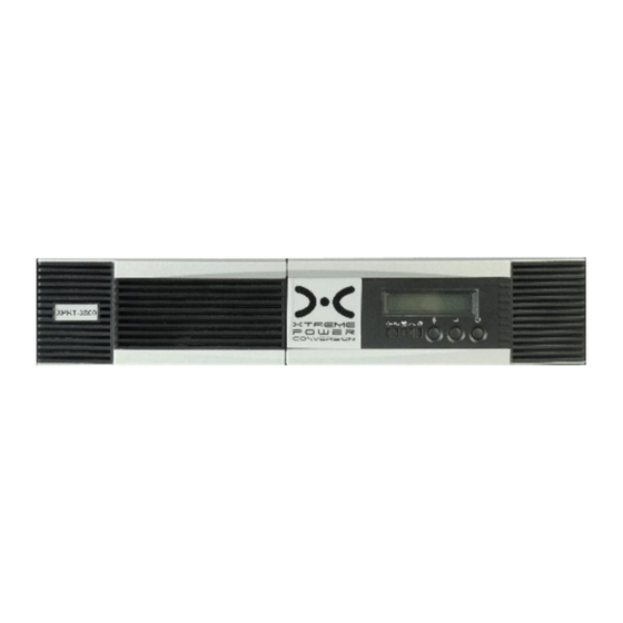
- Page 11 XPRT‐1000, XPRT‐1500, XPRT‐2000, XPRT‐3000 USER’S MANUALUNINTERRUPTIBLE POWER SUPPLY (UPS) “UPS ON” Indicator This LED is green when the UPS has been turned on and normal utility power is available. “ONLINE” Indicator This LED is green when the UPS is in normal or static bypass modes, and there is voltage at the output receptacles. “ON BATTERY” Indicator This LED is red when the UPS is operating in battery mode. “ON BYPASS” Indicator This LED is yellow when the UPS is in bypass mode. “FAULT” Indicator This LED is red if any internal error occurs in the UPS. An audible alarm will also be present. Press any of the buttons on the front panel to silence the alarm. FUNCTION BUTTON Press this button to choose which function you want on the LCD display. [11] ...
- Page 12 XPRT‐1000, XPRT‐1500, XPRT‐2000, XPRT‐3000 USER’S MANUALUNINTERRUPTIBLE POWER SUPPLY (UPS) ENTER BUTTON Press this button to check the content of the UPS LDC display. ON/OFF BUTTON Press this button and hold for 3 seconds to turn the UPS on. RS‐232 Standard Interface The RS‐232 interface uses a 9‐pin female D‐sub connector. Information provided includes data about utility, load and the UPS. The interface port pins and their functions are identified in the following table: PIN # SIGNAL NAME DIRECTION (RE: UPS) FUNCTIONS 2 TxD OUTPUT TxD OUTPUT 3 RxD INPUT RxD / INVERTER OFF INPUT 5 COMMON COMMON 6 OUTPUT AC FAIL OUTPUT 8 OUTPUT LOW BATTERY OUTPUT 9 OUTPUT 12VDC POWER CAUTION: MAX RATED VALUES 12VDC USB Port Connecting the UPS to your computer is accomplished through the USB port on the back of your computer. USB compliant hardware and operating system will be necessary, including installation of a ...
-
Page 13: Determining The Power Requirements Of Your Equipment
XPRT‐1000, XPRT‐1500, XPRT‐2000, XPRT‐3000 USER’S MANUALUNINTERRUPTIBLE POWER SUPPLY (UPS) Load Segments The power management software controls the sets of receptacles known as load segments, which can provide organized shutdown and startup of the equipment connected to the UPS. Less critical equipment can be turned off during power outages saving battery power for critical loads. The power management software instructions provide more detail regarding operation of this feature. The load group status can be viewed from the LCD display and can be changed if required. DETERMINING THE POWER REQUIREMENTS OF YOUR EQUIPMENT 1. Make sure the total Volt‐Amp (VA) requirements of your connected equipment does not exceed the maximum VA rating for the UPS. The maximum VA ratings are shown in the Specifications section of this document. 2. Ensure that the equipment plugged into the battery‐powered outlets does not exceed the UPS rated capacity. If UPS rated capacities are exceeded, an overload condition may occur and cause the UPS to shut down and trip the circuit breaker. 3. If the power requirements of your equipment are listed in values other than Volt‐Amps (VA), convert Watts (W) or Amps (A) into VA by doing the calculations below. Note: The equation below ... - Page 14 XPRT‐1000, XPRT‐1500, XPRT‐2000, XPRT‐3000 USER’S MANUALUNINTERRUPTIBLE POWER SUPPLY (UPS) Storage and Transportation Please handle the UPS and associated equipment with extreme caution since a high amount of energy is contained in the batteries. Always keep the unit in an upright position as marked on the packaging, and never drop the unit. Please adhere to the following instructions if the UPS is not installed immediately: • Store the equipment as is in its original packing and shipping carton. • Do not store in temperatures outside the range of ‐15°C to +25°C • Ensure that the equipment is fully protected from wet or damp areas and from moist air. In order to maintain the batteries, the UPS should be recharged every 6 months for at least 8 hours. If flammable substances such as gases or fumes are present, or if the room is airtight, a hazardous situation may exist in which no electrical equipment should be operated. The instructions in this manual explain how to install the UPS safely. Not acknowledging such electrical hazards may be fatal – keep this manual for future reference. WARNING! It is strongly recommended that the UPS cabinet not be opened as components have very high ...
- Page 15 XPRT‐1000, XPRT‐1500, XPRT‐2000, XPRT‐3000 USER’S MANUALUNINTERRUPTIBLE POWER SUPPLY (UPS) • Space and ventilation requirements must be met. Ensure there is 100mm behind and 50mm on the sides of the UPS for proper ventilation. • Ensure that the front of the UPS remains clear for user operation. INSTALLATION Vertical Installation Steps [15] ...
- Page 16 XPRT‐1000, XPRT‐1500, XPRT‐2000, XPRT‐3000 USER’S MANUALUNINTERRUPTIBLE POWER SUPPLY (UPS) Wall‐mounted Installation Steps [16] ...
- Page 17 XPRT‐1000, XPRT‐1500, XPRT‐2000, XPRT‐3000 USER’S MANUALUNINTERRUPTIBLE POWER SUPPLY (UPS) Stacked Installation Steps [17] ...
- Page 18 XPRT‐1000, XPRT‐1500, XPRT‐2000, XPRT‐3000 USER’S MANUALUNINTERRUPTIBLE POWER SUPPLY (UPS) Rack‐mount Installation Steps [18] ...
- Page 19 XPRT‐1000, XPRT‐1500, XPRT‐2000, XPRT‐3000 USER’S MANUALUNINTERRUPTIBLE POWER SUPPLY (UPS) Note: Any external Battery Packs must be installed next to or under the UPS. Please refer to the Battery Pack User Guide included in the Battery Pack box for more information when installing these. [19] ...
- Page 20 XPRT‐1000, XPRT‐1500, XPRT‐2000, XPRT‐3000 USER’S MANUALUNINTERRUPTIBLE POWER SUPPLY (UPS) Initial Connection and Startup: Ensure that the UPS and optional battery packs are mounted correctly, and the UPS is disconnected from input power before proceeding. 1. Connect external battery packs (option). • Use the cable from the External Battery Pack to connect to the UPS in the appropriate location. If a second External Battery Pack is being used, connect the cable from the second External Battery Pack to the appropriate connector in the rear of the 1 External ...
-
Page 21: User's Operations
XPRT‐1000, XPRT‐1500, XPRT‐2000, XPRT‐3000 USER’S MANUALUNINTERRUPTIBLE POWER SUPPLY (UPS) 5. Connect the USB or RS232 cable (included in the UPS packaging) to the Computer and UPS. Communication should start momentarily. If it does not, click on Setup on UPSMON toolbar, then select Comport, and search computer ports. CAUTION: Please verify the UPSMON shutdown settings of the UPS and Local PC by clicking on System/System configuration. 6. Click on Help in UPSMON toolbar for further software configuration. • Configure the optional SNMP card per Appendix “A” card instructions if option is installed. ... - Page 22 XPRT‐1000, XPRT‐1500, XPRT‐2000, XPRT‐3000 USER’S MANUALUNINTERRUPTIBLE POWER SUPPLY (UPS) • Push the ON / OFF button on the front control panel for five seconds. The audible alarm will sound and the UPS will shut down. • The LCD will display UPS OFF for a few seconds. • In emergency situations, the Emergency Power Off (EPO) located on the back of the UPS should be used. OPERATION Button Operation There are three operating buttons on the front panel. 1. ON / OFF BUTTON a. Push the ON / OFF BUTTON for at least 3 seconds to turn on the UPS b. Push the ON / OFF BUTTON for at least 5 seconds to turn the UPS off 2. ENTER BUTTON a. Push the ENTER BUTTON for at least 2 seconds to check content of the UPS. There are fifteen functions that can be checked. ...
- Page 23 XPRT‐1000, XPRT‐1500, XPRT‐2000, XPRT‐3000 USER’S MANUALUNINTERRUPTIBLE POWER SUPPLY (UPS) b. After choosing the function, push the ENTER BUTTON to enter the function that you want. c. Push the FUNCTION BUTTON to choose other functions. d. Push the ENTER BUTTON to enable the function selected. e. Push the ENTER BUTTON again to confirm and fully enable the function. If the ENTER BUTTON is not pressed within 10 seconds, the UPS will return to its original status. UPS LCD Meter Display Various measurements are available through the UPS LCD meter display LCD MESSAGE DESCRIPTION O/P VOLT = xxx, xV OUTPUT AC VOLTAGE O/P FREQ = xx, x Hz OUTPUT FREQUENCY I/P VOLT = xxx, xV INPUT AC VOLTAGE I/P FREQ = xx, x Hz INPUT FREQUENCY BAT VOLT = xx, xV BATTERY VOLTAGE O/P LOAD% = xx% LOAD % OF MAX LOAD ...
- Page 24 XPRT‐1000, XPRT‐1500, XPRT‐2000, XPRT‐3000 USER’S MANUALUNINTERRUPTIBLE POWER SUPPLY (UPS) Default Factory Settings FACTORY SETTINGS LCD DISPLAY SELECTION DEFAULT OUTPUT VOLTAGE SETTING O/P V 100/110/115/120/127 VAC 120 VAC (SELECT NOMINAL VOLTAGE) ±10% INPUT / BYPASS VOLTAGE I/P BYPASS +10 / ‐15 % +10 / ‐15 % (SELECT INPUT VOLTAGE RANGE WHEN BYPASS IS AVAILABLE) +15 / ‐20 % ±2% INPUT / FREQUENCY I/P F ±5% ±5% (SELECT INPUT FREQUENCY RANGE WHN UPS GOES INTO FREE FUN MODE) ±7% HIGH EFFICIENCY MODE SETTING HE MODE ON / OFF OFF (SELECT IF UPS IS TO RUN IN HIGH EFFICIENCY MODE) FREE RUN MODE FREE RUN ON / OFF ON (SELECT ...
- Page 25 XPRT‐1000, XPRT‐1500, XPRT‐2000, XPRT‐3000 USER’S MANUALUNINTERRUPTIBLE POWER SUPPLY (UPS) Manual Test of UPS A manual UPS or manual battery test can be conducted from the UPS configuration menu. Manual Battery Test: Scroll the parameters until MANUAL BAT TEST displays on the LDC. Press the ENTER BUTTON twice. Note: In order for the UPS and power management software to operate normally, MANUAL BYPASS should always be set to OFF as the load will not be protected by the UPS when MANUAL BYPASS is ON. The MANUAL BYPASS is intended to operate like an external maintenance bypass switch. Note: The UPS should be turned OFF and initialized via AC power before using the GENERATOR MODE function. [25] ...
-
Page 26: Batteries
XPRT‐1000, XPRT‐1500, XPRT‐2000, XPRT‐3000 USER’S MANUALUNINTERRUPTIBLE POWER SUPPLY (UPS) BATTERIES The life of batteries used in these UPS products is estimated at 3‐6 years depending on level of usage. Once the battery is no longer useful and must be replaced, please contact service personnel for assistance. REPLACING THE BATTERY (QUALIFIED SERVICE PERSONNEL ONLY) CAUTION! Read and follow the IMPORTANT SAFETY INSTRUCTIONS before servicing the battery. Service the battery under the supervision of Qualified Service Personnel knowledgeable of batteries and their precautions. CAUTION! Use only the specified type of battery. See your dealer for replacement batteries. CAUTION! The battery may present risk of electrical shock. Do not dispose of batteries in a fire as it may explode. Follow all local ordinances regarding proper disposal of batteries. ... -
Page 27: Troubleshooting
XPRT‐1000, XPRT‐1500, XPRT‐2000, XPRT‐3000 USER’S MANUALUNINTERRUPTIBLE POWER SUPPLY (UPS) TROUBLESHOOTING Displayed on Audible Alarm Description What You Should Do LCD Alarm The UPS is overloaded (in Line Shut off the least important equipment Mode). Your equipment needs Output Two Beeps connected to the UPS. If this solves the more power than the UPS can Overload per second overload problem, the UPS will switch provide. The UPS operates in from bypass back to normal operation. bypass. No action needed. The UPS will return to normal operation when it Battery Test No Beeps The UPS is doing a battery test. successfully completes the battery test. Constant Turn off protected loads. Turn off UPS Over‐Charge Batteries are overcharged. beep and call your local dealer The unit is operating on Battery 2 beeps Low Battery Power and will shut down soon due The unit will restart Automatically every ... -
Page 28: Specifications
XPRT‐1000, XPRT‐1500, XPRT‐2000, XPRT‐3000 USER’S MANUALUNINTERRUPTIBLE POWER SUPPLY (UPS) SPECIFICATIONS 120V MODEL XPRT-1000 XPRT-1500 XPRT-2000 XPRT-3000 INPUT Voltage 120 VAC (80 - 144V at 100% load) 60-144V at 40% load Capacity VA (W) 1000 VA (700 W) 1500 VA (1050 W) 2000 VA (1400 W) 3000 VA (2100 W) Frequency 50/60 Hz auto sensing Power Factor... - Page 29 XPRT‐1000, XPRT‐1500, XPRT‐2000, XPRT‐3000 USER’S MANUALUNINTERRUPTIBLE POWER SUPPLY (UPS) 120V MODEL XPRT-1000 XPRT-1500 XPRT-2000 XPRT-3000 UPS PHYSICAL Dimensions W x D x H (inches) W x D x H (inches) Unit Dimensions (2U) 16.9" x 16.7" x 3.5" 16.9" x 25.0" x 3.5" Shipping Dimensions 21.5" x 21.8" x 8.1" 21.7"...
- Page 30 XPRT‐1000, XPRT‐1500, XPRT‐2000, XPRT‐3000 USER’S MANUALUNINTERRUPTIBLE POWER SUPPLY (UPS) SHIPPING LIST 1. (1) UPS 2. (1) User’s and Installation Manual 3. (1) 6 ft USB‐DB9 adaptor cable 4. (1) UPSMON CD (monitoring software) 5. (1) phone cord (for use with telephone/data surge protection) 6. (2) sets of 5‐in‐1 mounting brackets 7. (1) set of horizontal mounting brackets [30] ...
-
Page 31: Obtaining Service
XPRT‐1000, XPRT‐1500, XPRT‐2000, XPRT‐3000 USER’S MANUALUNINTERRUPTIBLE POWER SUPPLY (UPS) OBTAINING SERVICE If the UPS requires Service: 1. Use the TROUBLESHOOTING section in this manual to eliminate obvious causes. 2. Verify there are no circuit breakers tripped. 3. Call your dealer for assistance. If you cannot reach your dealer, or if they cannot resolve the problem, call Xtreme Power Conversion Corp Technical Support at 800.582.4524. Technical support inquires can also be made at support@xpcc.com. Please have the following information available BEFORE calling the Technical Support Department: a. Your name and address. b. -
Page 32: Xtreme Power Conversion™ (Xpc) Corporation Limited Warranty
XPRT‐1000, XPRT‐1500, XPRT‐2000, XPRT‐3000 USER’S MANUALUNINTERRUPTIBLE POWER SUPPLY (UPS) XTREME POWER CONVERSION™ (XPC) CORPORATION LIMITED WARRANTY Xtreme Power Conversion (XPC) Corporation warrants Xtreme Power Conversion equipment, when properly applied and operated within specified conditions, against faulty materials or workmanship (excluding batteries) for a period of three years for XPRT‐Series products from the date of purchase. XPC ... -
Page 33: Appendix A: Battery Pack User Guide
XPRT‐1000, XPRT‐1500, XPRT‐2000, XPRT‐3000 USER’S MANUALUNINTERRUPTIBLE POWER SUPPLY (UPS) APPENDIX A: BATTERY PACK USER GUIDE LOAD QTY OF BATTERY PACKS MODEL VA WATTS UPS (1) BP1 (2) BP1 (1) BP2 (2) BP2 (1) BP3 (2) BP3 XPRT‐ 500 350 15 MIN 80 MIN 150 MIN 150 MIN 280 MIN N/A N/A 1000 1000 700 6 MIN 32 MIN 65 MIN 65 MIN 140 MIN N/A N/A XPRT‐ 750 525 13 MIN 40 MIN 80 MIN 80 MIN ... - Page 34 XPRT‐1000, XPRT‐1500, XPRT‐2000, XPRT‐3000 USER’S MANUALUNINTERRUPTIBLE POWER SUPPLY (UPS) BATTERY PACK INSTALLATION INSTRUCTIONS 1. Install the left side rail to the posts of the rack. 2. Install the right side rail to the posts of the rack. [34] ...
- Page 35 XPRT‐1000, XPRT‐1500, XPRT‐2000, XPRT‐3000 USER’S MANUALUNINTERRUPTIBLE POWER SUPPLY (UPS) 3. Place the Battery Pack on the rails. 4. Fasten the bracket to the left side of the Battery Pack. [35] ...
- Page 36 XPRT‐1000, XPRT‐1500, XPRT‐2000, XPRT‐3000 USER’S MANUALUNINTERRUPTIBLE POWER SUPPLY (UPS) 5. Fasten the bracket to the right side of the Battery Pack. 6. Slide the Battery Pack into position, and using screws, fasten the brackets to the front posts of the rack. [36] ...
- Page 37 XPRT‐1000, XPRT‐1500, XPRT‐2000, XPRT‐3000 USER’S MANUALUNINTERRUPTIBLE POWER SUPPLY (UPS) 7. Top view of the installed Battery Pack in the rack. 8. Close‐up view of the bracket on the post of the rack. [37] ...
- Page 38 XPRT‐1000, XPRT‐1500, XPRT‐2000, XPRT‐3000 USER’S MANUALUNINTERRUPTIBLE POWER SUPPLY (UPS) INSTRUCTIONS FOR CONNECTING THE BATTERY PACK(S) • Disconnect the UPS from the input utility power and remove all loads from the UPS before attempting to install a Battery Pack. Both battery circuit breakers (located on the rear of the units) must be OFF before proceeding. • Remove the steel cover from over the battery connector on the rear of the Battery Pack and the UPS. • Use the battery cable provided with the Battery Pack to connect the Battery Pack to the UPS. ...
- Page 39 XPRT‐1000, XPRT‐1500, XPRT‐2000, XPRT‐3000 USER’S MANUALUNINTERRUPTIBLE POWER SUPPLY (UPS) [39] ...
- Page 40 XPRT‐1000, XPRT‐1500, XPRT‐2000, XPRT‐3000 USER’S MANUALUNINTERRUPTIBLE POWER SUPPLY (UPS) [40] ...
- Page 41 XPRT‐1000, XPRT‐1500, XPRT‐2000, XPRT‐3000 USER’S MANUALUNINTERRUPTIBLE POWER SUPPLY (UPS) [41] ...
-
Page 42: Appendix B: Snmp Configuration Guide
XPRT‐1000, XPRT‐1500, XPRT‐2000, XPRT‐3000 USER’S MANUALUNINTERRUPTIBLE POWER SUPPLY (UPS) APPENDIX B: SNMP CONFIGURATION GUIDE • You must configure the Net Logic Card before it can operate properly. • You have two methods to configure the Net Logic Card: Using telnet or terminal listed below to access the configuration screen. • Once the SNMP card is configured and you have accessed the SNMP web page, you can view the user guide through the help section by clicking on the “?” link to further configure the SNMP card to site parameters. CAUTION : A default setting of the SNMP card is to shutdown the UPS after 300 seconds when a utility power failure occurs. Changes to this setting can only be made through the web interface after the initial configuration with Telnet or Terminal is completed. To make changes to this setting: 1. Log into the web browser by typing the IP address in the browser’s address bar. 2. Enter the username and password of dnpower for both fields. 3. Go to the configuration tab and select Event actions. 4. Highlight Power Failure and hit select. 5. Scroll down to Power Failure‐Shutdown and uncheck “Enable”. This disables the feature 6. Leaving “Enable” checked and changing the delay time will shutdown the UPS when a power failure occurs after the specified delay time is reached. Using Telnet 1. Make sure the Net Logic Card is plugged in the UPS properly. 2. Connect a network cable to the LAN connector on the Net Logic Card. 3. Telnet to the Net Logic Card from the PC via the path described below: Start/run/telnet 192.168.1.254 4. Use dnpower for the User Name and for the Password. 5. A Configuration Screen is displayed. Note: The default IP address of the Card is 192.168.1.254. The default login user name and password are both dnpower. Using Terminal 1. Make sure the Net Logic Card is plugged in the UPS properly. ... - Page 43 XPRT‐1000, XPRT‐1500, XPRT‐2000, XPRT‐3000 USER’S MANUALUNINTERRUPTIBLE POWER SUPPLY (UPS) 5. Make sure the serial port is not used by any program on your PC. 6. Run a terminal program, such as HyperTerminal. 7. Configure the serial port for 9600 bps, no parity, 8 data bits, 1 stop bit, and no flow control. 8. Reboot the Net Logic Card. 9. Press ESC key right after reboot. The Card/Box will detect if the user presses a ESC key for 5 seconds. If so, it will allow the user to log in; otherwise, it will try to initialize the external MODEM for other usages. So you have to press the ESC key as quickly as possible. You may keep holding the ESC without releasing it right after the system is started to make sure it will not be too late or missing. 10. Use dnpower for the User Name and for the Password. 11. A Configuration Screen is displayed. Note: The default login user name and password are both dnpower. Configuration Screen When you enter into the Configuration Screen, the following menu is displayed: .NETpower SNMP agent adapter Configuration ############################### <# Main Menu #> ############################### 1) SNMP Agent IP Parameter 2) MIB‐II System Group 3) SNMP read/write Access Control 4) SNMP Trap Receivers 5) UPS Properties 6) System Time & Time Server 7) User Account 8) E‐mail Setting 9) Environmental Monitoring Module w) Web and Telnet Service Setting u) Upgrade firmware r) Restore Default Configuration Data b) Reboot SNMP agent adapter s) Save & Reboot Exit Without Saving Enter Choice >> SNMP Agent IP Parameter [43] ...
- Page 44 XPRT‐1000, XPRT‐1500, XPRT‐2000, XPRT‐3000 USER’S MANUALUNINTERRUPTIBLE POWER SUPPLY (UPS) To configure the SNMP agent IP parameters, enter a 1 at the main menu. The following screen will appear allowing you to configure IP address, Subnet Mask and Gateway. .NETpower SNMP agent adapter Configuration IP Parameter Setup My IP Address: 192.168.1.254 Subnet Mask: 255.255.255.0 Router/Gateway IP Address: 192.168.1.1 1) Set IP Address 2) Set Subnet Mask 3) Set Router/Gateway IP Address <0> Return to previous menu Enter Choice >> MIB‐II System Group Enter a 2 at the main menu, the following screen will be displayed allowing you to configure some important MIB‐II System Group items, including system name, contact person and system location. .NETpower SNMP agent adapter Configuration MIB‐II System Group Setup Menu Current values for the following MIB‐II OID: sysName: NETpower sysContact: admin sysLocation: 1) Set sysName 2) Set sysContact 3) Set sysLocation <0> Return to previous menu Enter Choice >> SNMP Read/Write Access Control Enter a 3 at the main menu, the following screen will be displayed allowing you to setup the SNMP Access Control. Enter the community number (from 1 to 4) to specify a community string, an IP address, and the access privilege. .NETpower SNMP agent adapter Configuration SNMP Access Control Setup Menu Community name IP address Access [44] ...
- Page 45 XPRT‐1000, XPRT‐1500, XPRT‐2000, XPRT‐3000 USER’S MANUALUNINTERRUPTIBLE POWER SUPPLY (UPS) #1 #2 #3 #4 1) Set Access Control #1 2) Set Access Control #2 3) Set Access Control #3 4) Set Access Control #4 <0> Return to previous menu Enter Choice >> SNMP Trap Receivers Enter a 4 at the main menu, the following screen will be displayed allowing you to setup the SNMP Trap Receivers. The Severity includes Any, Server, Warning and Informational. The Any means any event will be sent to the trap receiver. The Severe means only severe events will be sent to the trap receiver. The Warning means only warning events will be sent to the trap receiver. The Informational means only informational events will be sent to the trap receiver. The Generation item is used to enable or disable trap generation. .NETpower SNMP agent adapter Configuration SNMP Trap Receiver Setup Menu IP address Community Severity Generation #1 #2 192.168.1.2 public any disable #3 #4 1) Set trap receiver #1 2) Set trap receiver #2 3) Set trap receiver #3 4) Set trap receiver #4 <0> Return to previous menu Enter Choice >> UPS Properties Enter a 5 at the main menu; the following screen will be displayed allowing you to setup the UPS Properties, including UPS Identification Name, UPS Attached Device and Last Battery Replacement Date. .NETpower SNMP agent adapter Configuration UPS Properties Setup UPS Identification Name: UPS UPS Attached Device: NA Last Battery Replacement Date: 12/31/1969 [45] ...
- Page 46 XPRT‐1000, XPRT‐1500, XPRT‐2000, XPRT‐3000 USER’S MANUALUNINTERRUPTIBLE POWER SUPPLY (UPS) 1) Set UPS Identification Name 2) Set UPS Attached Device 3) Set Last Battery Replacement Date <0> Return to previous menu Enter Choice >> System Time & Time Server Enter a 6 at the main menu, the following screen will be displayed allowing you to setup System Time. In this option, you can setup the date and time for the Net Logic Card. The SNTP Server and Time Zone settings are used for time adjustment. Specify the SNTP Server and Time Zone, and then choose 4 Adjust System Time to adjust your system time. If the values retrieved from the Internet are not what you want, you can still change the date and time manually . .NETpower SNMP agent adapter Configuration System Time & Time Server Setup System Time: 01/07/2003 11:08:37 Time Server IP Address: 200.49.40.1 Time Zone: 0+ 1) Set System Time 2) Set Time Server IP Address 3) Time Zone 4) Adjust System Time <0> Return to previous menu Enter Choice >> User Account Enter a 7 at the main menu, the following screen will be displayed allowing yo u to setup user accounts those who can login to the Net Logic Card. .NETpower SNMP agent adapter Configuration User Account Setup Menu User name Password #1 dnpower ******** #2 ******** #3 ******** #4 ******** 1) Set User Account #1 2) Set User Account #2 3) Set User Account #3 4) Set User Account #4 <0> Return to previous menu Enter Choice >> [46] ...
- Page 47 XPRT‐1000, XPRT‐1500, XPRT‐2000, XPRT‐3000 USER’S MANUALUNINTERRUPTIBLE POWER SUPPLY (UPS) E‐mail Setting Enter an 8 at the main menu; the following screen will be displayed allowing you to setup SMTP server. You have to setup it correctly so that the .NETpower device can sent out mails when an event occurs. .NETpower SNMP agent adapter Configuration Email Parameter Setup SMTP Server IP Address: 1) Set SMTP IP Address <0> Return to previous menu Enter Choice >> Environmental Monitoring Module Enter a 9 at the main menu to setup the Environmental Monitoring Module. You have to install Environmental Monitoring Module before setup. Web and Telnet Service Setting Enter w at the main menu to enable/disable Web/Telnet service. Enable Web Service when you want to monitor the UPS via a web browser. Enable or disable Telnet Service to specify whether it allows users to login via telnet. .NETpower SNMP agent adapter Configuration Web and Telnet Service Setup Menu Web Service: disable Telnet Service: enable 1) enable Web Service 2) disable Telnet Service <0> Return to previous menu Enter Choice >> Upgrade Firmware Enter u at the main menu to upgrade firmware. .NETpower SNMP agent adapter Configuration Upgrade firmware ========================== 1) Upgrade firmware from tftp server 2) Upgrade firmware from http server <0> Return to previous menu Enter Choice >> [47] ...
- Page 48 XPRT‐1000, XPRT‐1500, XPRT‐2000, XPRT‐3000 USER’S MANUALUNINTERRUPTIBLE POWER SUPPLY (UPS) When you choose 1, the following screen is displayed asking you to input the tftp server and the filename of the latest firmware. To make it work, you must have a tftp server installed and copy the firmware file to the tftp server. Input the tftp server address >> 192.168.1.1 Input the file name >> dnpower.bin When you choose 2, the following screen is displayed asking you to input the url pointed to the firmware file. To make it work, you must have a web server installed and copy the firmware file to the web server. Input the URL (Example: http://192.168.1.1/dnpower.bin) >> http://192.168.1.1/dnpower.bin [48] ...
- Page 49 XPRT‐1000, XPRT‐1500, XPRT‐2000, XPRT‐3000 USER’S MANUALUNINTERRUPTIBLE POWER SUPPLY (UPS) Restore Default Configuration Data To reset the configuration data, enter r at the main menu. When the next menu is displayed, choose 1 to reset all values to their factory default settings, or choose 0 to return to the previous menu without resetting the data. .NETpower SNMP agent adapter Configuration Restore default data ========================== 1) Yes, Do it <0> Return to previous menu Enter Choice >> Reboot SNMP Agent Adapter Enter b at the main menu to reboot the .NETpower device. All settings will not be saved. When the next menu is displayed, choose 1 to reboot the .NETpower device, or choose 0 to return to the previous menu. .NETpower SNMP agent adapter Configuration Reboot ========================== 1) Yes, Do it <0> Return to previous menu Enter Choice >> Save & Reboot To save configuration data and reboot, enter s at the main menu. When the next menu is displayed, choose 1 to save configuration data and reboot the .NETpower device, or choose 0 to return to the previous menu. .NETpower SNMP agent adapter Configuration Save & Exit ========================== 1) Yes, Do it <0> Return to previous menu Enter Choice >> Exit Without Saving Enter x at the main menu to exit the Configuration Screen [49] ...
Need help?
Do you have a question about the XPRT‐1000 and is the answer not in the manual?
Questions and answers